check engine AUDI A4 1995 B5 / 1.G ATQ Engine Oxygen Sensor Control Checking
[x] Cancel search | Manufacturer: AUDI, Model Year: 1995, Model line: A4, Model: AUDI A4 1995 B5 / 1.GPages: 63, PDF Size: 0.31 MB
Page 2 of 63
24-77
If voltage change does not occur or occurs only
slowly, the following malfunctions could be
present:
Slits or holes in sensor head clogged.
Sensors suffered thermal overload.
Transition resistance in signal wire or Ground
(GND) wire.
Sensor too cold, sensor heating not
functioning.
Sensor damaged by contact spray or similar
substance (contact spray is drawn through the
fine hollow interiors by thermal fluctuations and
capillary action into the electrical wiring in
sensor).
Sensor damaged by silicon vapors (the use of
sealants containing silicon leads to trace
elements of silicon being taken in by the
engine. These silicon elements are not
combusted and damage the oxygen sensor).
Pa
ge 2 of 63 Ox
yg
en sensor control, checkin
g
11/23/2002 htt
p://127.0.0.1:8080/audi/servlet/Dis
play?action=Goto&t
yp
e=re
pair&id=AUDI.B5.FU05.24.3
Page 5 of 63
24-80
Function test
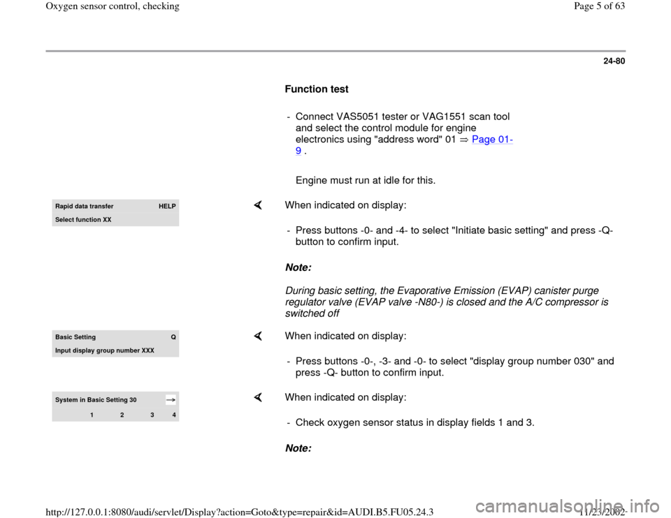
- Connect VAS5051 tester or VAG1551 scan tool
and select the control module for engine
electronics using "address word" 01 Page 01
-
9 .
Engine must run at idle for this.Rapid data transfer
HELP
Select function XX
When indicated on display:
Note:
During basic setting, the Evaporative Emission (EVAP) canister purge
regulator valve (EVAP valve -N80-) is closed and the A/C compressor is
switched off - Press buttons -0- and -4- to select "Initiate basic setting" and press -Q-
button to confirm input.
Basic Settin
g
Q
Input displa
y group number XXX
When indicated on display:
- Press buttons -0-, -3- and -0- to select "display group number 030" and
press -Q- button to confirm input.
System in Basic Setting 30
1
2
3
4
When indicated on display:
Note: - Check oxygen sensor status in display fields 1 and 3.
Pa
ge 5 of 63 Ox
yg
en sensor control, checkin
g
11/23/2002 htt
p://127.0.0.1:8080/audi/servlet/Dis
play?action=Goto&t
yp
e=re
pair&id=AUDI.B5.FU05.24.3
Page 7 of 63
24-81
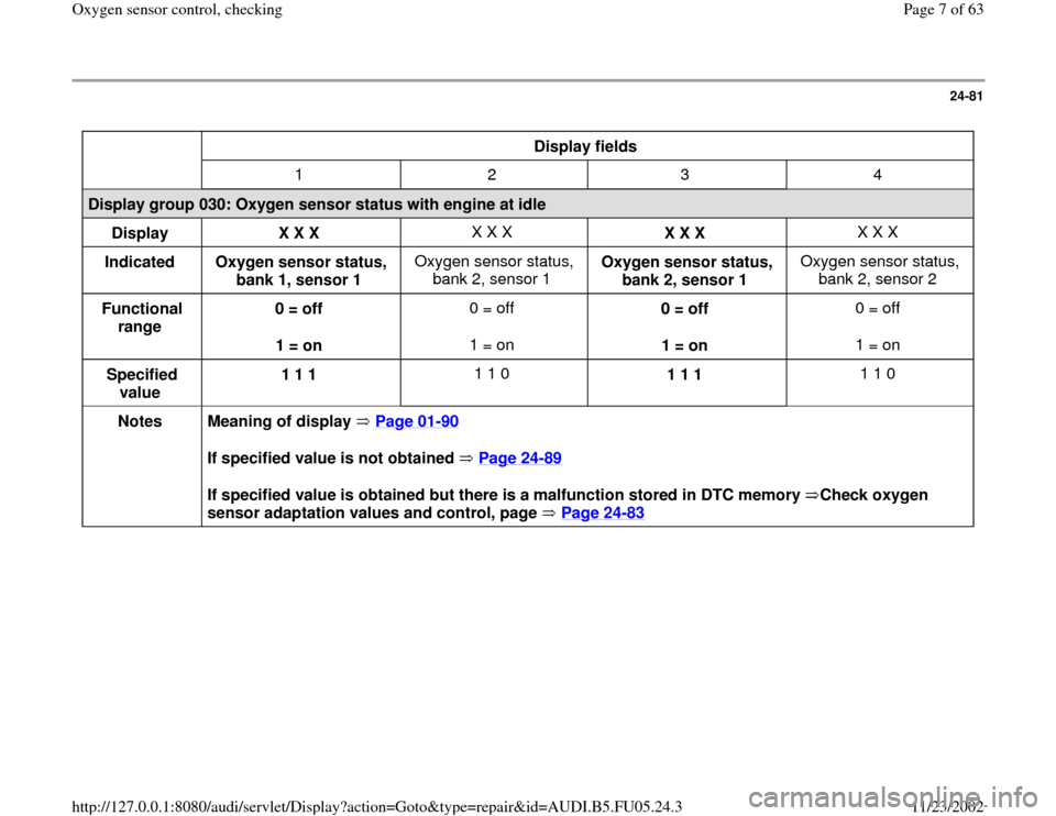
Display fields
1 2 3 4
Display group 030: Oxygen sensor status with engine at idle
Display
X X X X X X
X X X X X X
Indicated
Oxygen sensor status,
bank 1, sensor 1 Oxygen sensor status,
bank 2, sensor 1 Oxygen sensor status,
bank 2, sensor 1 Oxygen sensor status,
bank 2, sensor 2
Functional
range 0 = off
1 = on 0 = off
1 = on 0 = off
1 = on 0 = off
1 = on
Specified
value 1 1 1 1 1 0
1 1 1 1 1 0
Notes
Meaning of display Page 01
-90
If specified value is not obtained Page 24
-89
If specified value is obtained but there is a malfunction stored in DTC memory Check oxygen
sensor adaptation values and control, page Page 24
-83
Pa
ge 7 of 63 Ox
yg
en sensor control, checkin
g
11/23/2002 htt
p://127.0.0.1:8080/audi/servlet/Dis
play?action=Goto&t
yp
e=re
pair&id=AUDI.B5.FU05.24.3
Page 8 of 63
24-82
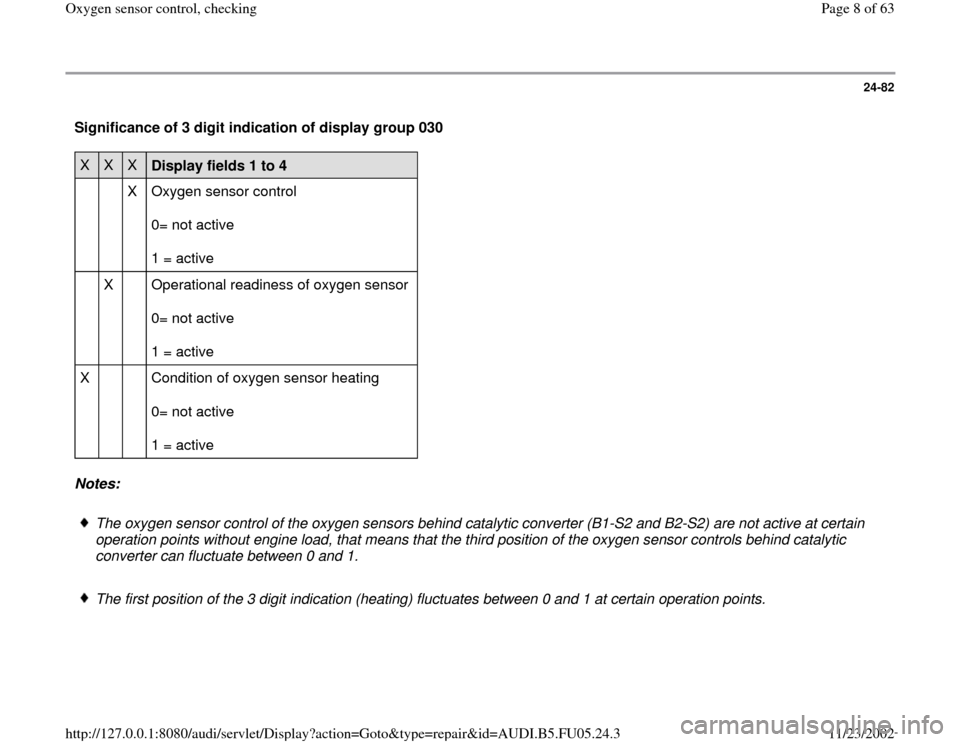
Significance of 3 digit indication of display group 030 X
X
X
Display fields 1 to 4
X Oxygen sensor control
0= not active
1 = active
X Operational readiness of oxygen sensor
0= not active
1 = active
X Condition of oxygen sensor heating
0= not active
1 = active
Notes:
The oxygen sensor control of the oxygen sensors behind catalytic converter (B1-S2 and B2-S2) are not active at certain
operation points without engine load, that means that the third position of the oxygen sensor controls behind catalytic
converter can fluctuate between 0 and 1.
The first position of the 3 digit indication (heating) fluctuates between 0 and 1 at certain operation points.
Pa
ge 8 of 63 Ox
yg
en sensor control, checkin
g
11/23/2002 htt
p://127.0.0.1:8080/audi/servlet/Dis
play?action=Goto&t
yp
e=re
pair&id=AUDI.B5.FU05.24.3
Page 18 of 63
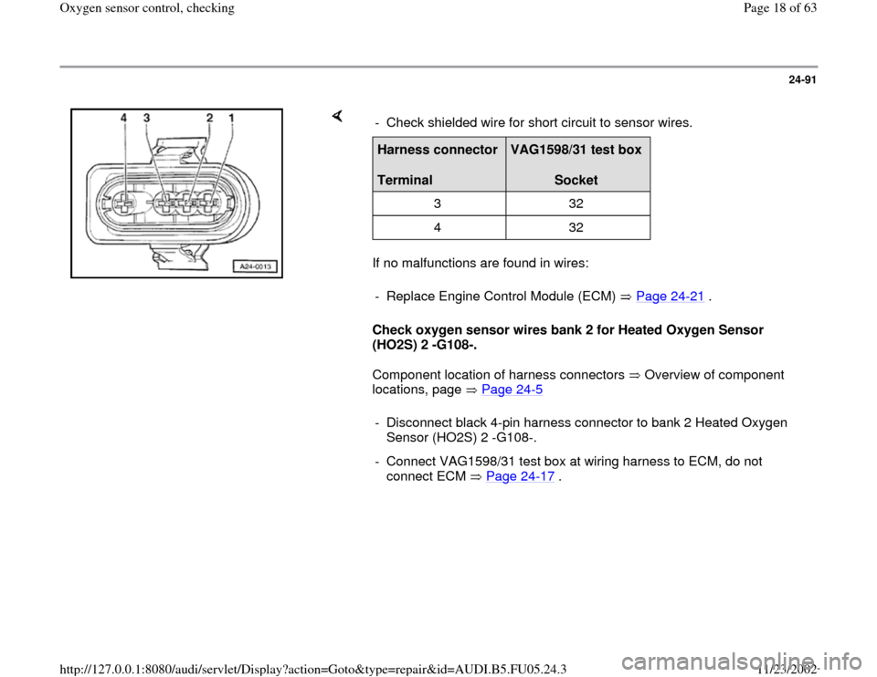
24-91
If no malfunctions are found in wires:
Check oxygen sensor wires bank 2 for Heated Oxygen Sensor
(HO2S) 2 -G108-.
Component location of harness connectors Overview of component
locations, page Page 24
-5 - Check shielded wire for short circuit to sensor wires.
Harness connector
Terminal
VAG1598/31 test box
Socket
3 32
4 32
- Replace Engine Control Module (ECM) Page 24
-21
.
- Disconnect black 4-pin harness connector to bank 2 Heated Oxygen
Sensor (HO2S) 2 -G108-.
- Connect VAG1598/31 test box at wiring harness to ECM, do not
connect ECM Page 24
-17
.
Pa
ge 18 of 63 Ox
yg
en sensor control, checkin
g
11/23/2002 htt
p://127.0.0.1:8080/audi/servlet/Dis
play?action=Goto&t
yp
e=re
pair&id=AUDI.B5.FU05.24.3
Page 19 of 63
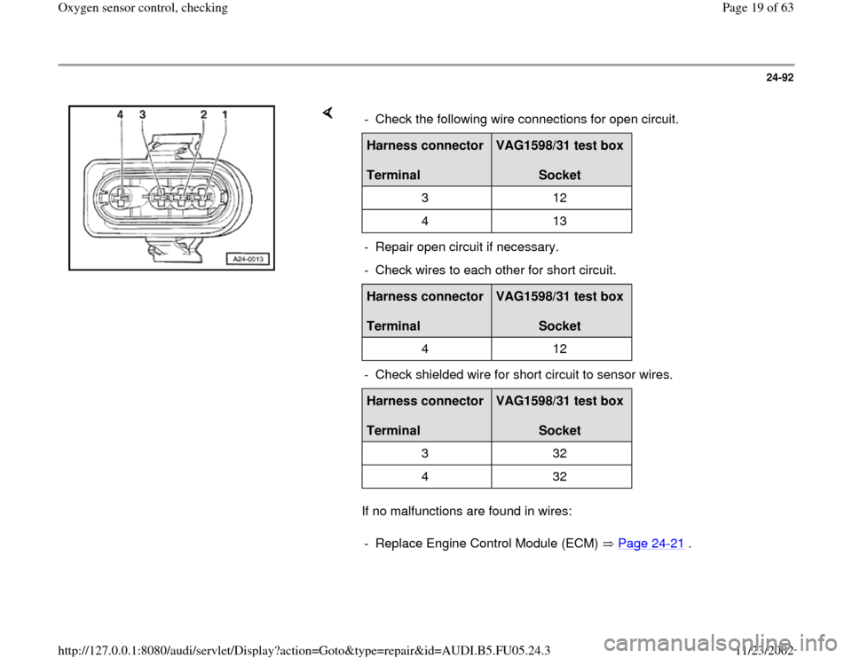
24-92
If no malfunctions are found in wires: - Check the following wire connections for open circuit.Harness connector
Terminal
VAG1598/31 test box
Socket
3 12
4 13
- Repair open circuit if necessary.
- Check wires to each other for short circuit.Harness connector
Terminal
VAG1598/31 test box
Socket
4 12
- Check shielded wire for short circuit to sensor wires.Harness connector
Terminal
VAG1598/31 test box
Socket
3 32
4 32
- Replace Engine Control Module (ECM) Page 24
-21
.
Pa
ge 19 of 63 Ox
yg
en sensor control, checkin
g
11/23/2002 htt
p://127.0.0.1:8080/audi/servlet/Dis
play?action=Goto&t
yp
e=re
pair&id=AUDI.B5.FU05.24.3
Page 21 of 63
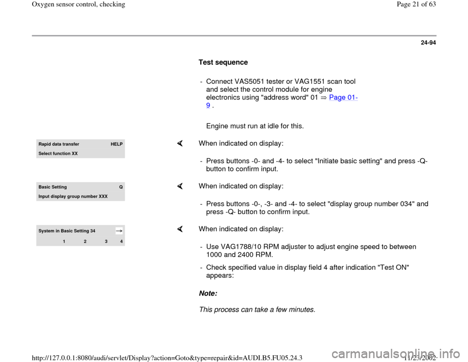
24-94
Test sequence
- Connect VAS5051 tester or VAG1551 scan tool
and select the control module for engine
electronics using "address word" 01 Page 01
-
9 .
Engine must run at idle for this.Rapid data transfer
HELP
Select function XX
When indicated on display:
- Press buttons -0- and -4- to select "Initiate basic setting" and press -Q-
button to confirm input.
Basic Settin
g
Q
Input display group number XXX
When indicated on display:
- Press buttons -0-, -3- and -4- to select "display group number 034" and
press -Q- button to confirm input.
System in Basic Setting 34
1
2
3
4
When indicated on display:
Note:
This process can take a few minutes. - Use VAG1788/10 RPM adjuster to adjust engine speed to between
1000 and 2400 RPM.
- Check specified value in display field 4 after indication "Test ON"
appears:
Pa
ge 21 of 63 Ox
yg
en sensor control, checkin
g
11/23/2002 htt
p://127.0.0.1:8080/audi/servlet/Dis
play?action=Goto&t
yp
e=re
pair&id=AUDI.B5.FU05.24.3
Page 22 of 63
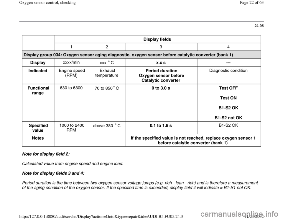
24-95
Display fields
1 2 3 4
Display group 034: Oxygen sensor aging diagnostic, oxygen sensor before catalytic converter (bank 1)
Display xxxx/min
xxx C
x.x s
---
Indicated Engine speed
(RPM) Exhaust
temperature Period duration
Oxygen sensor before
Catalytic converter Diagnostic condition
Functional
range 630 to 6800
70 to 850 C
0 to 3.0 s
Test OFF
Test ON
B1-S2 OK
B1-S2 not OK
Specified
value 1000 to 2400
RPM above 380 C 0.1 to 1.8 s B1-S2 OK
Notes
If the specified value is not reached, replace oxygen sensor 1
before catalytic converter (bank 1)
Note for display field 2:
Calculated value from engine speed and engine load.
Note for display fields 3 and 4:
Period duration is the time between two oxygen sensor voltage jumps (e.g. rich - lean - rich) and is therefore a measurement
of the aging condition of the oxygen sensor. If the specified time is exceeded, display field 4 will indicate = B1-S1 not OK.
Pa
ge 22 of 63 Ox
yg
en sensor control, checkin
g
11/23/2002 htt
p://127.0.0.1:8080/audi/servlet/Dis
play?action=Goto&t
yp
e=re
pair&id=AUDI.B5.FU05.24.3
Page 24 of 63
24-96
- Press buttons -0-, -3- and -5- to select "display
group number 035" and press -Q- button to
confirm input. System in Basic Setting 35
1
2
3
4
When indicated on display:
Note:
The test in display group 035 is activated simultaneously with the test in
display group 034 Therefore the test result is indicated immediately after
display group 035 is selected. - Check specified value in display field 4.
Display fields
1 2 3 4
Display group 035: Oxygen sensor aging diagnostic, oxygen sensor before catalytic converter (bank 2)
Display xxxx/min
xxx C
x.x s
---
Indicated Engine speed
(RPM) Exhaust
temperature Period duration
Oxygen sensor before
Catalytic converter Diagnostic condition
Functional
range 630 to 6800
70 to 850 C
0 to 3.0 s
B1-S2 OK
B1-S2 not OK
Specified
value 1000 to 2400
RPM above 380 C 0.1 to 1.8 s B1-S2 OK
Notes
If the specified value is not reached, replace oxygen sensor 2
Pa
ge 24 of 63 Ox
yg
en sensor control, checkin
g
11/23/2002 htt
p://127.0.0.1:8080/audi/servlet/Dis
play?action=Goto&t
yp
e=re
pair&id=AUDI.B5.FU05.24.3
Page 27 of 63
24-98
Notes:
The oxygen sensor control behind catalytic
converter overrules the oxygen sensor control
before catalytic converter. It serves as a
corrective control.
Test requirements:
Test sequence
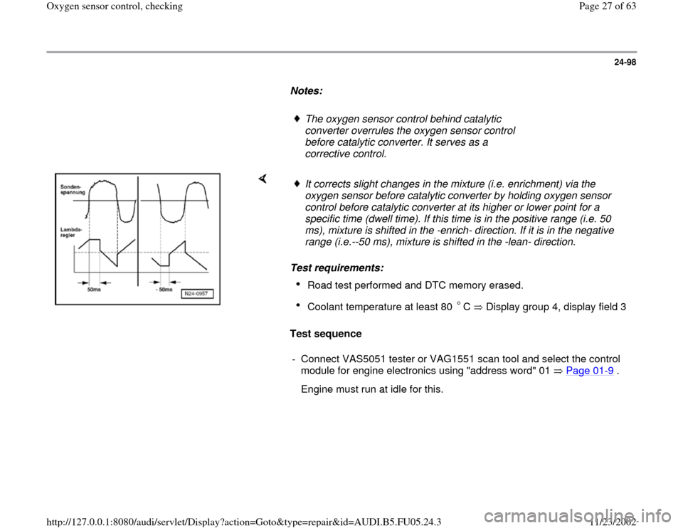
It corrects slight changes in the mixture (i.e. enrichment) via the
oxygen sensor before catalytic converter by holding oxygen sensor
control before catalytic converter at its higher or lower point for a
specific time (dwell time). If this time is in the positive range (i.e. 50
ms), mixture is shifted in the -enrich- direction. If it is in the negative
range (i.e.--50 ms), mixture is shifted in the -lean- direction. Road test performed and DTC memory erased. Coolant temperature at least 80 C Display group 4, display field 3
- Connect VAS5051 tester or VAG1551 scan tool and select the control
module for engine electronics using "address word" 01 Page 01
-9 .
Engine must run at idle for this.
Pa
ge 27 of 63 Ox
yg
en sensor control, checkin
g
11/23/2002 htt
p://127.0.0.1:8080/audi/servlet/Dis
play?action=Goto&t
yp
e=re
pair&id=AUDI.B5.FU05.24.3