sensor AUDI A6 1997 C5 / 2.G ATW Engine Ignition System User Guide
[x] Cancel search | Manufacturer: AUDI, Model Year: 1997, Model line: A6, Model: AUDI A6 1997 C5 / 2.GPages: 59, PDF Size: 0.53 MB
Page 34 of 59
28-33
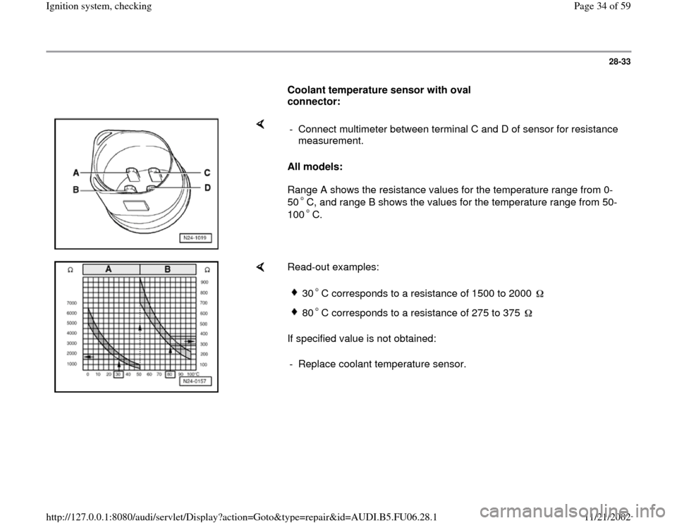
Coolant temperature sensor with oval
connector:
All models:
Range A shows the resistance values for the temperature range from 0-
50 C, and range B shows the values for the temperature range from 50-
100 C. - Connect multimeter between terminal C and D of sensor for resistance
measurement.
Read-out examples:
If specified value is not obtained:
30 C corresponds to a resistance of 1500 to 2000 80 C corresponds to a resistance of 275 to 375
- Replace coolant temperature sensor.
Pa
ge 34 of 59 I
gnition s
ystem, checkin
g
11/21/2002 htt
p://127.0.0.1:8080/audi/servlet/Dis
play?action=Goto&t
yp
e=re
pair&id=AUDI.B5.FU06.28.1
Page 35 of 59
28-34
If specified value is obtained:
- Connect VAG1598/31 test box at wiring harness
to Engine Control Module (ECM), do not connect
ECM Page 24
-19
.
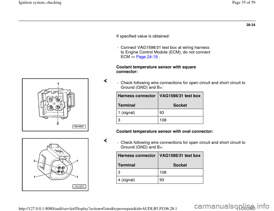
Coolant temperature sensor with square
connector:
Coolant temperature sensor with oval connector: - Check following wire connections for open circuit and short circuit to
Ground (GND) and B+: Harness connector
Terminal
VAG1598/31 test box
Socket
1 (signal) 93
3 108
- Check following wire connections for open circuit and short circuit to
Ground (GND) and B+: Harness connector
Terminal
VAG1598/31 test box
Socket
3 108
4 (signal) 93
Pa
ge 35 of 59 I
gnition s
ystem, checkin
g
11/21/2002 htt
p://127.0.0.1:8080/audi/servlet/Dis
play?action=Goto&t
yp
e=re
pair&id=AUDI.B5.FU06.28.1
Page 44 of 59
28-40
Knock recognition control stop,
checking
If a DTC is stored regarding "Knock control
regulation limit reached":
- Perform following tests:
Possible cause
Corrective action
DTC for all cylinders
Poor fuel quality
Operating instructions - Change fuel quality
or
Cylinder 1/2 or 3/4
Knock sensor tightened to incorrect torque- Loosen knock sensors and tighten to 20 Nm
Knock sensor faulty- Check knock sensor Page 28
-41
Corrosion at harness connector- Check harness connector
Engine accessories loose- Secure engine accessories
DTC for one Cylinder
Engine damage- Check compression pressure
Engine accessories loose- Secure engine accessories
Pa
ge 44 of 59 I
gnition s
ystem, checkin
g
11/21/2002 htt
p://127.0.0.1:8080/audi/servlet/Dis
play?action=Goto&t
yp
e=re
pair&id=AUDI.B5.FU06.28.1
Page 45 of 59
28-41
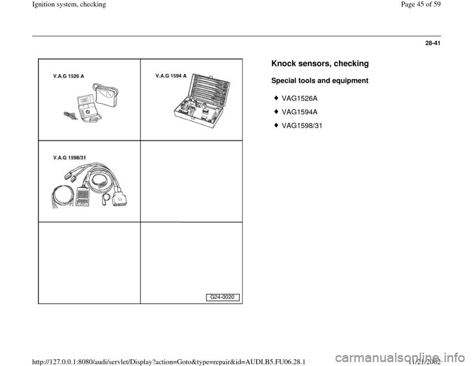
Knock sensors, checking
Special tools and equipment
VAG1526A
VAG1594A
VAG1598/31
Pa
ge 45 of 59 I
gnition s
ystem, checkin
g
11/21/2002 htt
p://127.0.0.1:8080/audi/servlet/Dis
play?action=Goto&t
yp
e=re
pair&id=AUDI.B5.FU06.28.1
Page 46 of 59
28-42
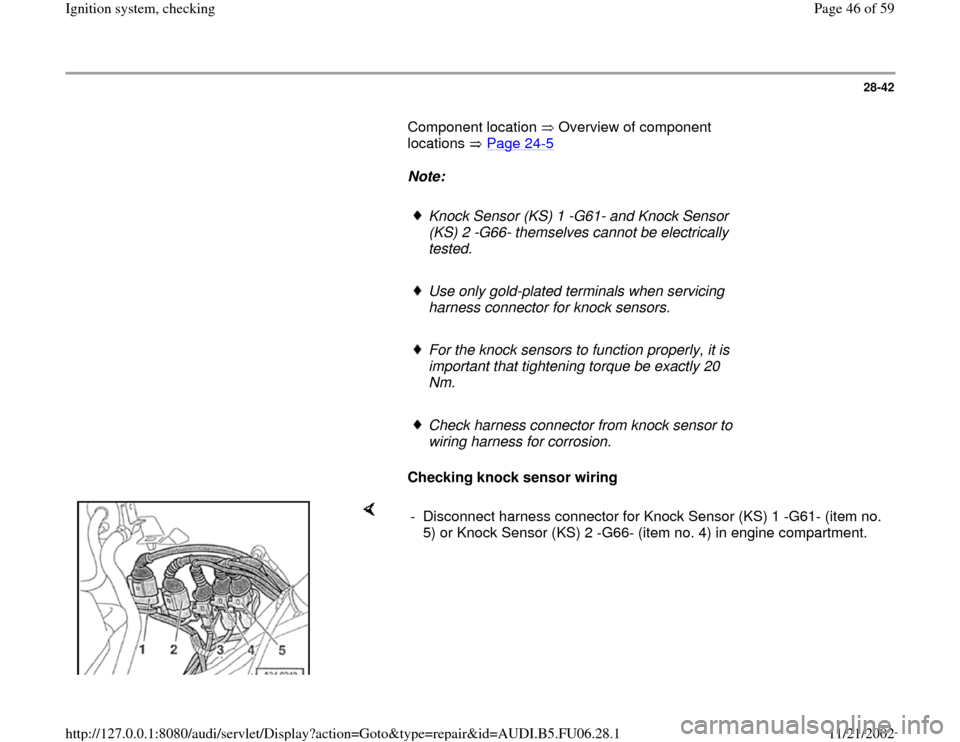
Component location Overview of component
locations Page 24
-5
Note:
Knock Sensor (KS) 1 -G61- and Knock Sensor
(KS) 2 -G66- themselves cannot be electrically
tested.
Use only gold-plated terminals when servicing
harness connector for knock sensors.
For the knock sensors to function properly, it is
important that tightening torque be exactly 20
Nm.
Check harness connector from knock sensor to
wiring harness for corrosion.
Checking knock sensor wiring
- Disconnect harness connector for Knock Sensor (KS) 1 -G61- (item no.
5) or Knock Sensor (KS) 2 -G66- (item no. 4) in engine compartment.
Pa
ge 46 of 59 I
gnition s
ystem, checkin
g
11/21/2002 htt
p://127.0.0.1:8080/audi/servlet/Dis
play?action=Goto&t
yp
e=re
pair&id=AUDI.B5.FU06.28.1
Page 47 of 59
28-43
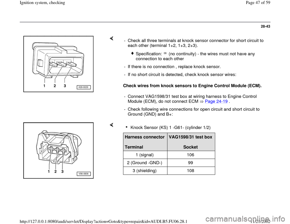
Check wires from knock sensors to Engine Control Module (ECM). - Check all three terminals at knock sensor connector for short circuit to
each other (terminal 1+2, 1+3, 2+3).
Specification: (no continuity) - the wires must not have any
connection to each other
- If there is no connection , replace knock sensor.
- If no short circuit is detected, check knock sensor wires:
- Connect VAG1598/31 test box at wiring harness to Engine Control
Module (ECM), do not connect ECM Page 24
-19
.
- Check following wire connections for open circuit and short circuit to
Ground (GND) and B+:
Knock Sensor (KS) 1 -G61- (cylinder 1/2)
Harness connector
Terminal
VAG1598/31 test box
Socket
1 (signal) 106
2 (Ground -GND-) 99
3 (shielding) 108
Pa
ge 47 of 59 I
gnition s
ystem, checkin
g
11/21/2002 htt
p://127.0.0.1:8080/audi/servlet/Dis
play?action=Goto&t
yp
e=re
pair&id=AUDI.B5.FU06.28.1
Page 48 of 59
28-44
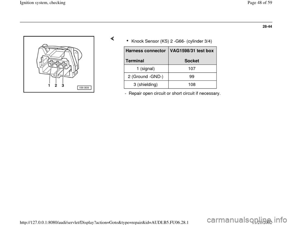
Knock Sensor (KS) 2 -G66- (cylinder 3/4)
Harness connector
Terminal
VAG1598/31 test box
Socket
1 (signal) 107
2 (Ground -GND-) 99
3 (shielding) 108
- Repair open circuit or short circuit if necessary.
Pa
ge 48 of 59 I
gnition s
ystem, checkin
g
11/21/2002 htt
p://127.0.0.1:8080/audi/servlet/Dis
play?action=Goto&t
yp
e=re
pair&id=AUDI.B5.FU06.28.1
Page 49 of 59
28-45
Camshaft Position (CMP) sensor 2 -G40-,
checking
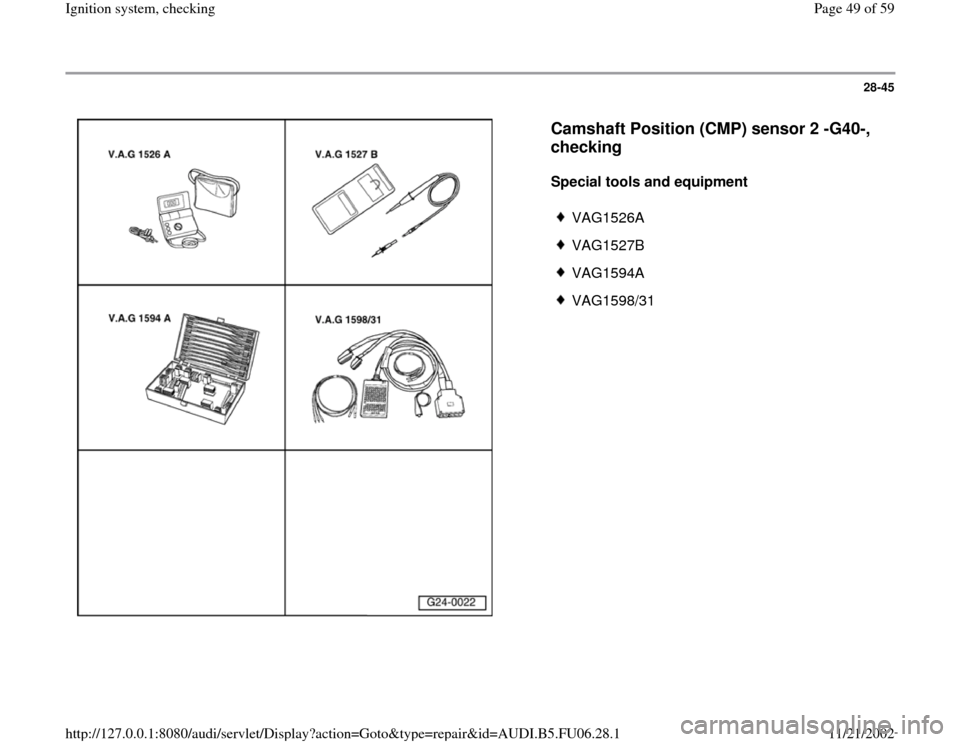
Special tools and equipment
VAG1526A
VAG1527B
VAG1594A
VAG1598/31
Pa
ge 49 of 59 I
gnition s
ystem, checkin
g
11/21/2002 htt
p://127.0.0.1:8080/audi/servlet/Dis
play?action=Goto&t
yp
e=re
pair&id=AUDI.B5.FU06.28.1
Page 50 of 59
28-46
Component location Overview of component
locations Page 24
-5
The Camshaft Position (CMP) sensor provides
the ignition position for cylinder 1.
For failure, knock control is switched off and the
ignition angle is retarded slightly since a cylinder
allocation is no longer possible. In addition, the
boost pressure of the turbocharger is decreased.
Engine will continue to run without Camshaft
Position (CMP) sensor signal and can also be
restarted:
When a malfunction is recognized, the Engine
Control Module (ECM) initiates one ignition
spark per cylinder for each crankshaft rotation.
The offset of one engine rotation will have no
noticeable effect on the injection. Instead of
occurring with intake valves open, injection will
be "pre-loaded" (in front of closed intake valve).
This has only a minor effect on the quality of the
mixture preparation.
Pa
ge 50 of 59 I
gnition s
ystem, checkin
g
11/21/2002 htt
p://127.0.0.1:8080/audi/servlet/Dis
play?action=Goto&t
yp
e=re
pair&id=AUDI.B5.FU06.28.1
Page 51 of 59
28-47
Checking activation
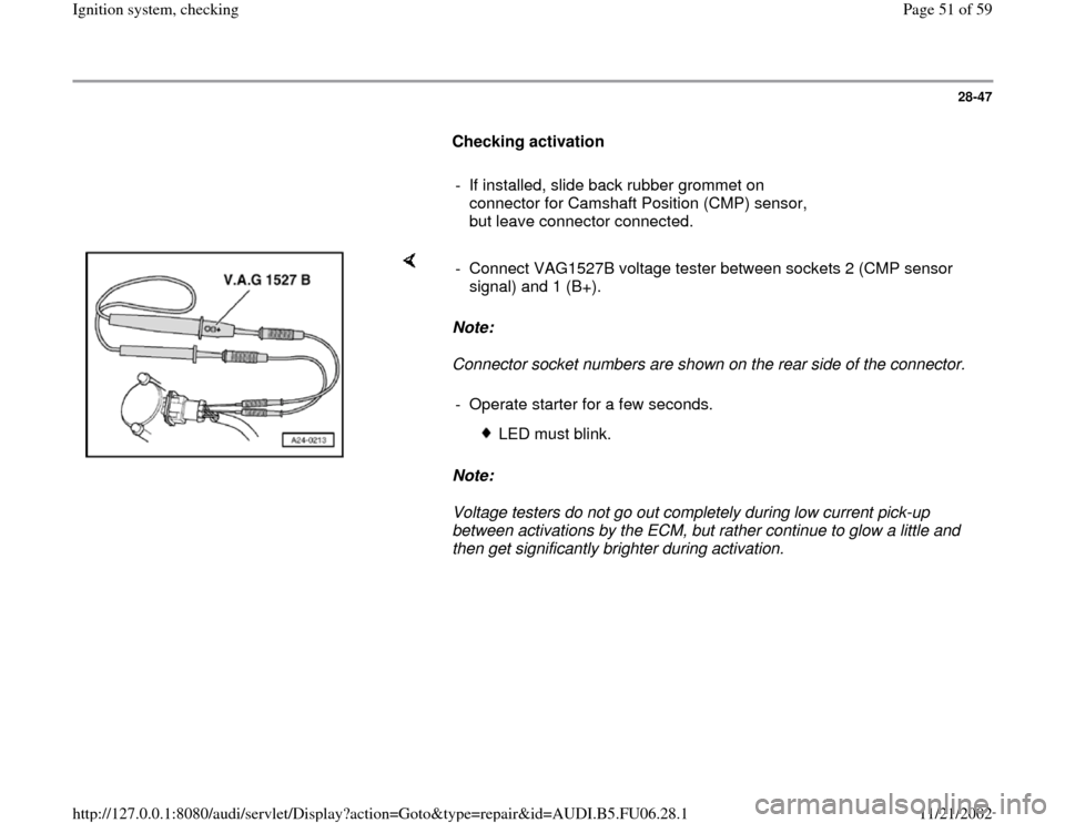
- If installed, slide back rubber grommet on
connector for Camshaft Position (CMP) sensor,
but leave connector connected.
Note:
Connector socket numbers are shown on the rear side of the connector.
Note:
Voltage testers do not go out completely during low current pick-up
between activations by the ECM, but rather continue to glow a little and
then get significantly brighter during activation. - Connect VAG1527B voltage tester between sockets 2 (CMP sensor
signal) and 1 (B+).
- Operate starter for a few seconds.
LED must blink.
Pa
ge 51 of 59 I
gnition s
ystem, checkin
g
11/21/2002 htt
p://127.0.0.1:8080/audi/servlet/Dis
play?action=Goto&t
yp
e=re
pair&id=AUDI.B5.FU06.28.1