display AUDI Q3 2019 Owners Manual
[x] Cancel search | Manufacturer: AUDI, Model Year: 2019, Model line: Q3, Model: AUDI Q3 2019Pages: 280, PDF Size: 72.73 MB
Page 4 of 280
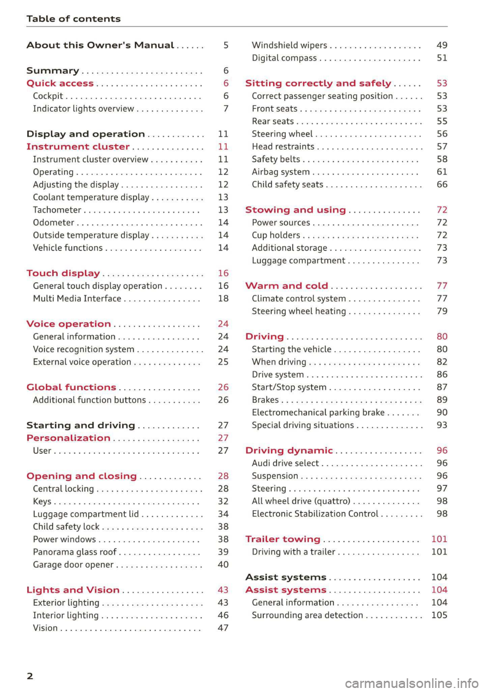
Table of contents
About this Owner's Manual......
SUMIMALY: ; « ss6% : osen ss sean cs poe s
QC CCeS Skis: si esis a 6 ores os ewe
Cockpit... 2... ee eee eee eee
Indicator lights overview...........0.
Display and operation............
Instrument cluster...............
Instrument cluster overview...........
Operating. ecco ws swacemn o © aero o erm 9
Adjusting the display.................
Coolant temperature display...........
Tachometer’. series s ewie so sie ¥ & overs
Odometer............ 0. cee eee eee eee
Outside temperature display...........
Vehicle functions « se-0 2. ese ve eee ees
Touch’ display . 22... : secs ie eses ees
General
touch display operation........
Multi Media Interface................
Voice operation..................
Generalinformation.................
Voice recognition system..............
External voice operation..............
Global functions.................
Additional function buttons...........
Starting and driving.............
Personalization..................
Luggage compartment lid.............
Child safety lock sa04 45 eec4 es eee e ee ees
Power Windows. . 6 sce « 6 umes #6 enna o
Panorama glass roof...............--
Garage door Opener’: sens ss esas se cess
Lights and Vision.................
Exterior lighting sees < = sees « « eee% sv oe
Interior liQhtingios . esas + exe ee ews x
VISION... eee eee
NOD
OO
13)
16 16 18
24 24 24
25
26 26 27 27 27 28 28
32
34
38 38 39
40
43 43
46 47
Windshield wipers............--..+-- 49
Digital compass............0 000 eens 51
Sitting correctly and safely...... 53
Correct passenger seating position...... 53
FROntSeats|; + acres s 2 sees ss aan ae ee a 53
Rearseats sic 2 sea oo awn oo coon 7 9 oe 55
Steering wheel............00--000 00s 56
Head restraints..................000. 57
Safety belts: « ssa: s 2 wens 5 2 worms x s sawn 58
Airbag system... .. cc eee eee eee 61
Child safety seats..............0.00.. 66
Stowing and using............... 72
Power SOUrCeES ...... eee eee eee 72
Cup Holders: « saws = ¢ seme + ¢ eas ¢ e ees 72
Additional storage...............005. 73
Luggage compartment............... 73
MVEA COLD css 2 3 asic ¥ & mame @ owe vag
Climate control system............... 77
Steering wheel heating............... 79
DOUNTINY 5 sressies oc & nensnte 6 0 eyertn © « suetans «ox 80
Starting the vehicle................-. 80
When driving:s: + csys = cece ee ees eee 82
DEIVE SYSEE Mc «0 ameneime 6 meneme 6 ot cuenet = ate 86
Start/Stop system ..........2..00 eee 87
Brak@s’: < « qemy + quvep x 2 mee gs meme es ew 89
Electromechanical parking brake....... 90
Special driving situations.............. 93
Driving dynamic.................. 96
Audi drive select..................00. 96
SUSPENSION s: « s sass < & ees § ¢ ees ee ee 96
STCOTING & wesw os soars wo woeaNe ww asteRTNG w Fae 97
All wheel drive (quattro).............. 98
Electronic Stabilization Control......... 98
Trailer towing.................... 101
Driving with atrailer................. 101
ASSISTISYSTEMMS © cssesic ss csssers & wassuers oa 104
Assist systems.................-. 104
General information . 00.4. ec0. 6 sews 104
Surrounding area detection............ 105
Page 5 of 280
83A012721BA
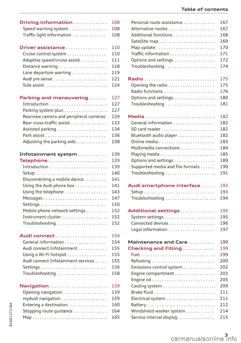
Table of contents
Driving information.............. 108
Speed warning system.........-..000- 108
Traffic light information.............. 108
Driver assistance................. 110
Cruise control systeM.......... 000 eee 110
Adaptive speed/cruise assist........... 111
Distance warning.................005 118
Lane departure warning............... 119
AUdi PrOSONsSe & seis + 2 mews 2» nee 2 oem 121
Side assist... 2... eee eee eee eee 124
Parking and maneuvering....... 127
IMtroduetion « x cicvers < e ersuens + x enavane oo saree 127
Parking system plus...............04. 127
Rearview camera and peripheral cameras. 129
Rear cross-traffic assist. ............-. 133
Assisted parking .............0.00005- 134
Parkassist': sexs « s neem sg aes + e wae 2 136
Adjusting the parking aids............. 138
Infotainment system............ 139
Telephone
Introduction
Setup..........
Disconnecting a mobile device......... 141
Using the Audi phone box............. 141
Using the telephone................0. 143
MESSAGES crus + ¢ ween ¢ 3 eeuen xy eee 4 2 ae 147
SOttiMGSicraice o saaneme « u eneneve © icameneies © eyeaeite 150
Mobile phone network settings......... 152
Instrument cluster.............2-.00. 152
Troubleshooting sais . eves 6 coarse es cae 152
AU CONMECE ces ¢ s xeee x 2 ews a i ee 154
Generalinformation................. 154
Audi connect Infotainment............ 155
Using a Wi-Fi hotspot................ 155
Audi connect Infotainment services..... 155
Settings............0 0.0000... 0000. 156
Troubleshooting sass ss eee ss ees ss ees 158
IIS VIG ABI. 5 cccccas os cones o enemies aoe 15S:
Opening navigation.................. 159
myAudi navigation.................0. 159
Entering adestination................ 160
Stopping route guidance.............. 164
Maize: = 2 sews ¢ 2 Som & eee Ee ees Fe eee 165
Personal route assistance............. 167
Alternative routes............02e000 167
Additional functions................. 168
Satellite mapiee e «sons e siemens ae aacens 2 4 ve 169
Map update............. 0. eee eee eee 170
Tratficintoritiationie: « : waa: xs seen 6 2 eu LZ)
Options and settings.............000e 172
Troubleshooting...............-.000- 174
R&GIO’: onic cs wea ss wens se eee & o Hews 175
Opening the radio................04. 175
Radio functions..................-4. 176
Options and settings...............0. 180
Troubleshooting.................0005 181
MG@Gias = acs ¢ = secs s © seme « s Seems so SeURS 182
General information ................. 182
SD card reader..........0.-..00 eee 182
Bluetooth audio player.............0. 182
Online Medias « ssi + exes ae omens oo veer 183
Multimedia connections.............. 184
Playing tedia. = s sees s 2 sees se wees ee 185
Options and settings...............0. 189
Supported media and file formats...... 190
Troubleshooting «ess 2s secu se vee ss ees 191
Audi smartphone interface...... 193
Setup... ee eee eee eee eee 193
Troubleshooting............ee eee eee 194
Additional settings.............. 195
SySteMm Settings: < saws ss sews se eee & 195
Connected devices............ 0 cee ee 196
Legal information................... 197
Maintenance and Care........... 199
Checking and Filling............. 199
FUGlaias s os08,8 & aay @ § aovon & § Sanne 8 OF eee 199
RePUCLING: is «a cms so ewes oe ese vB seen 200
Emissions control system............. 202
Engine compartment................. 203
EMGIMeiOils: acre « ¢ qaiea & © meee s 2 seNoN 8 Es 205
Cooling system. ............--00 00 eee 209
Brake fluid... . 0... eee eee eee 211
Electrical system.........--.0----05- 211
Battery. =o cecness « ommnaine « 0 omecwne 6 3 oats = oe 212
Windshield washer system............ 214
Service interval display............... 215
Page 8 of 280
Quick access
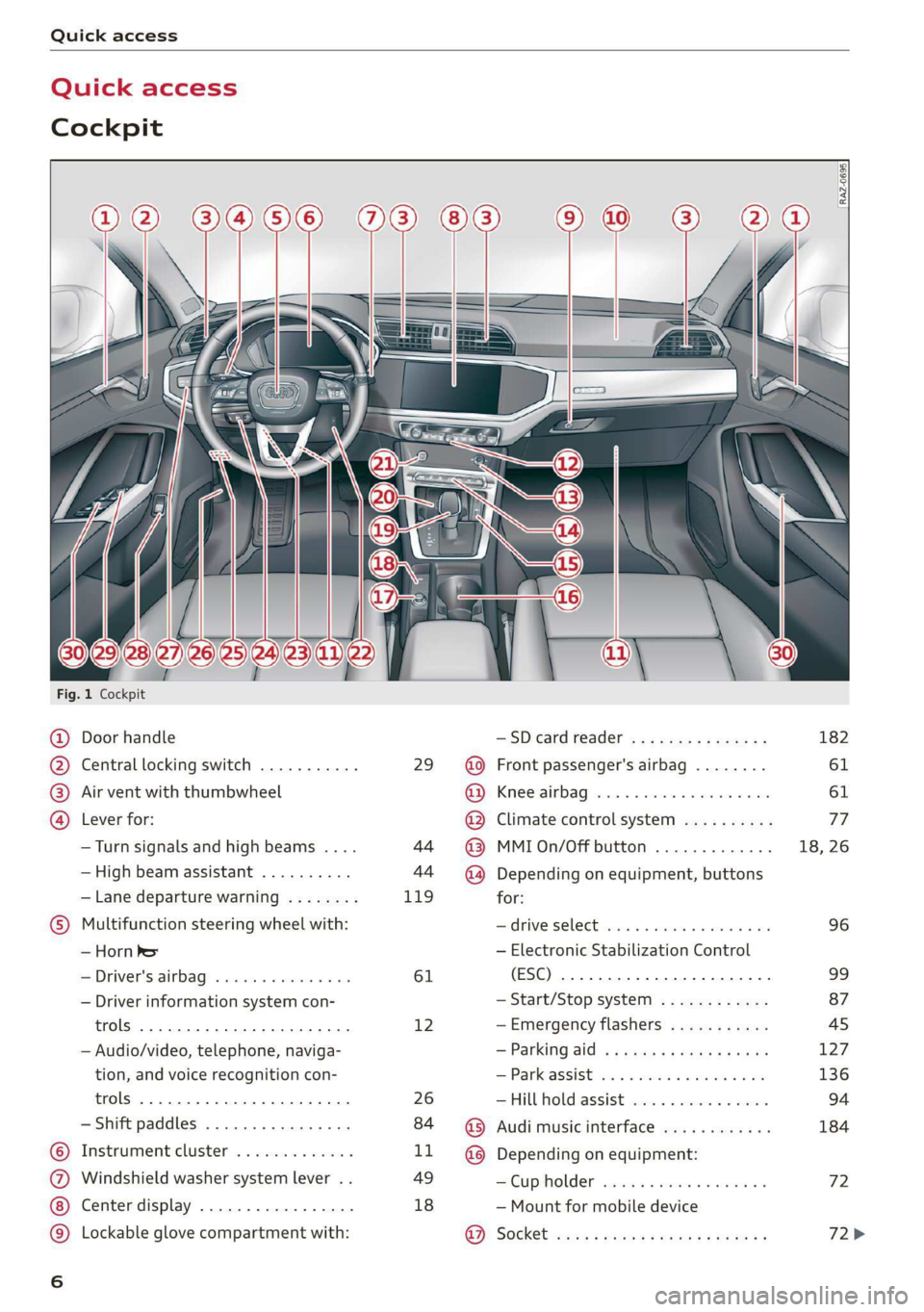
Quick access
Cockpit
3 g|
3
q
i
Fig. 1 Cockpit
@ Door handle —SDcardreader ............... 182
@ Central locking switch ........... 29 @ Front passenger's airbag ........ 61
® Air vent with thumbwheel @ Knee airbag ...............2... 61
@ Lever for: @ Climate control system .......... 77
—Turn signals and high beams .... 44 @ MMIOn/Off button ............. 18, 26
— High beam assistant .......... 44 ~@) Depending on equipment, buttons
— Lane departure warning ........ 119 for:
© Multifunction steering wheel with: Sdrive SELECE causss 6 6 soaaye os mess 6 wee 96
— Horn be — Electronic Stabilization Control
— Driver's airbag .............4. 61 (ESC) 2... ee eee eee eee 99
— Driver information system con- — Start/Stop system ............ 87
trols 2... ee eee eee eee 12 —Emergency flashers ........... 45
— Audio/video, telephone, naviga- = Parking atd) « « sews « 2 aaeny a © caune 127
tion, and voice recognition con- —Parkassist ..............000- 136
trols 2.0... eee eee 26 —Hill hold assist ............0.. 94
— Shift paddles ................ 84 @ Audi music interface ............ 184
© Instrument cluster ............. LL @ Depending on equipment:
@ Windshield washer system lever . . 49 —Cupholder ..............0005 72
Center display ................. 18 — Mount for mobile device
© Lockable glove compartment with: 9). Socket sassy 2 yasy ss cane a & wae ae 72>
oa
Page 9 of 280
83A012721BA
Quick access
Electromechanical parking brake
button ......... cece eee eee 90
Selector lever (automatic transmis-
SION) 26... eee ee eee eee 82
Audi phone Dox esessie so seas & 6 cere 141
START ENGINE STOP] button .... 80
Depending on equipment: ®®®
— Starting the engine when there is
amalfunction ............0005 81
—Ignition lock ................. 80
@3) Steering wheel adjustment ...... 56
@4 Lever for:
— Cruise control system ......... 110
— Adaptive cruise assist .......... 111
@) Data link connector for On Board
Diagnostic System (OBD) ........ 255
@8 Hood release .............0.0.. 204
@) Buttons for:
—~ CIGKES! mu: ¢ ¢ sem x ¢ etme Fo cee 43
—All-weather lights ............ 43
Luggage compartment lid button . 34
@3 Exterior mirror adjustment ...... 47
G0 Buttons for:
— Power windows .............. 38
—Child safety lock .............. 38
@ Tips
Some the equipment listed here is only instal-
led in certain models or is available as an op-
tion.
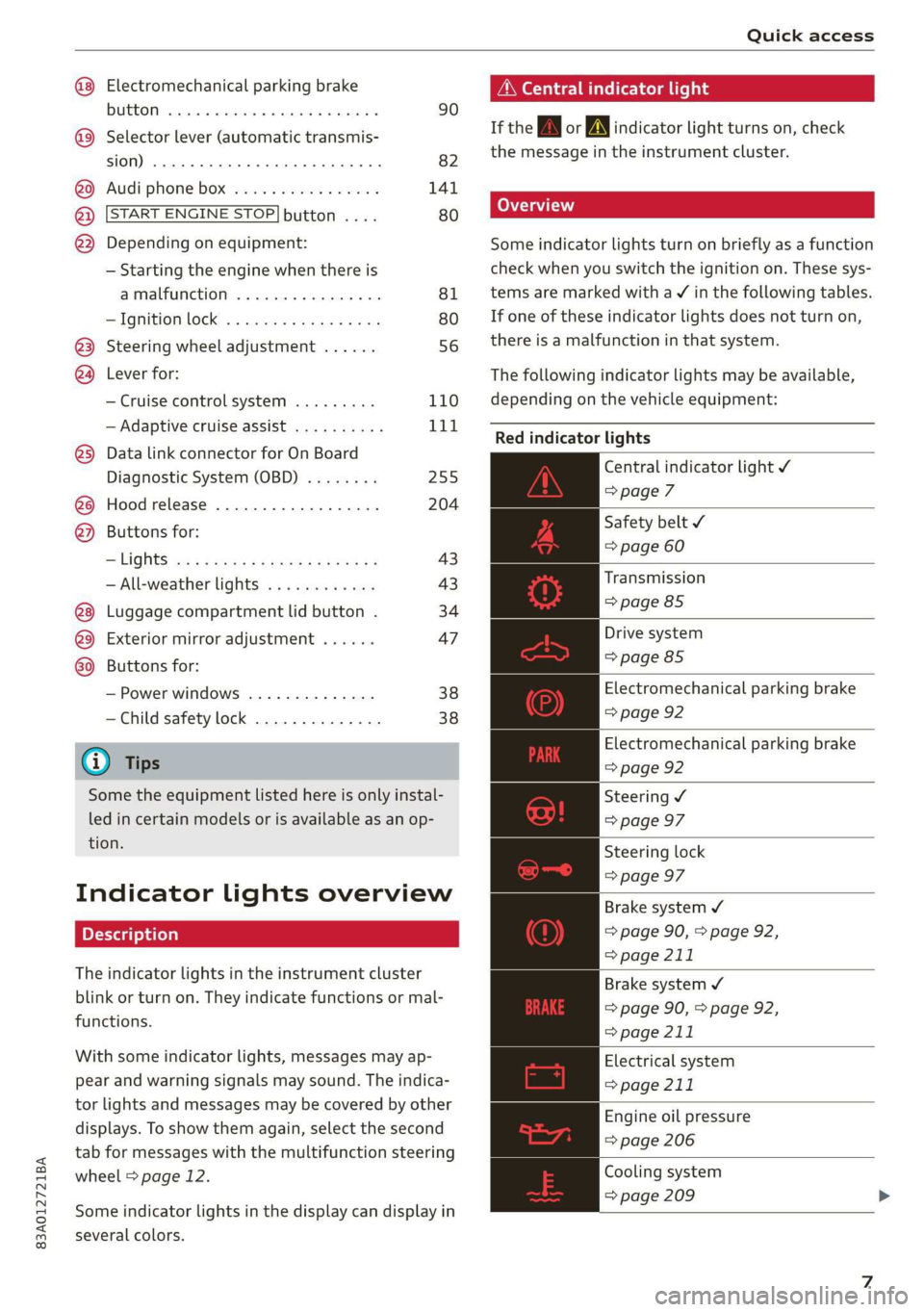
Indicator lights overview
The indicator lights in the instrument cluster
blink or turn on. They indicate functions or mal-
functions.
With some indicator lights, messages may ap-
pear and warning signals may sound. The indica-
tor lights and messages may be covered by other
displays. To show them again, select the second
tab for messages with the multifunction steering
wheel > page 12.
Some indicator lights in the display can display in
several colors.
A\ Central indicator light
If the wa or A indicator light turns on, check
the message in the instrument cluster.
Some indicator lights turn on briefly as a function
check
when you switch the ignition on. These sys-
tems are marked with a V in the following tables.
If one of these indicator lights does not turn on,
there is a malfunction in that system.
The following indicator lights may be available,
depending on the vehicle equipment:
Red indicator lights
Central indicator light ¥
=>page 7
Safety belt
=> page 60
Transmission
=> page 85
Drive system
=> page 85
Electromechanical parking brake
=> page 92
Electromechanical parking brake
=> page 92
Steering ¥
=> page 97
Steering lock
=> page 97
Brake system ¥
=> page 90, > page 92,
=> page 211
Brake system 4
=> page 90, > page 92,
=> page 211
Electrical system
=> page 211
Engine oil pressure
=> page 206
Cooling system
=> page 209
Page 13 of 280
83A012721BA
Instrument cluster
‘ul ant cluster
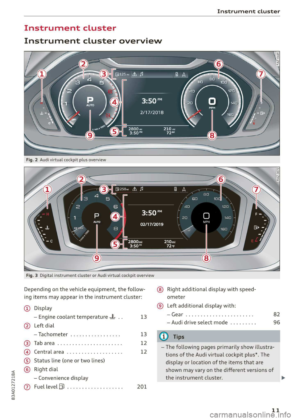
Instrument cluster overview
HO
2/17/2018
3:50™
02/17/2019
Fig. 3 Digital instrument cluster or Audi virtual cockpit overview
Depending on the vehicle equipment, the follow-
ing items may appear in the instrument cluster:
Right additional display with speed-
ometer
(9) Left additional display with:
@) Display
— Engine coolant temperature ~E .. 13 Gear... eee eee eee
5) Left dial — Audi drive select mode .........
D: be’
= Tachometer sss s x sews 2 2 eee 13 @ Tips
ue — The following pages primarily show illustra-
i tions of the Audi virtual cockpit plus*. The
©) Status line (one or two lines) display or location of the items that are
) Right dial shown may vary on the different versions of
— Convenience display the instrument cluster.
@ Fuellevel BD i ects ss cews sc enas es 201
11
>
Page 14 of 280
Instrument cluster
— You can select the units used for tempera-
ture, speed, and other measurements
=> page 195.
— Speeds are displayed in mph (miles per
hour) or km/h (kilometers per hour).
— If there is a malfunction in the instrument
cluster, DEF will appear in the trip odometer
display. Have the malfunction corrected as
soon as possible.
Operating
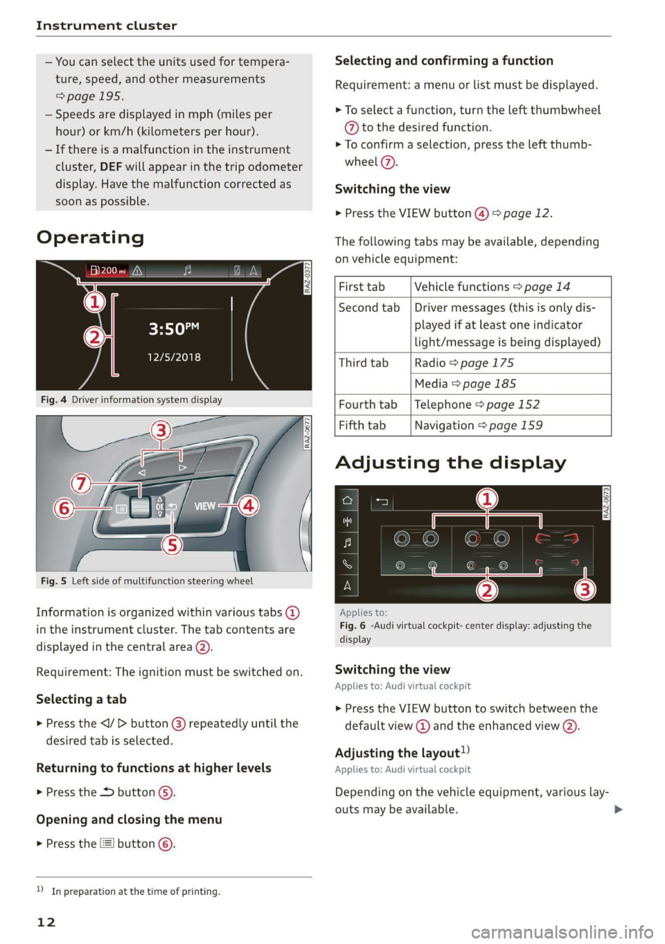
eH) hee
12/5/2018
Selecting and confirming a function
Requirement: a menu or list must be displayed.
> To select a function, turn the left thumbwheel
@ to the desired function.
> To confirm a selection, press the left thumb-
wheel (7).
Switching the view
> Press the VIEW button @) > page 12.
The following tabs may be available, depending
on vehicle equipment:
First tab Vehicle functions > page 14
Second tab | Driver messages (this is only dis-
played if at least one indicator
light/message is being displayed)
Third tab Radio > page 175
Media
> page 185
Fig. 4 Driver information system display Fourth tab | Telephone > page 152
Fifth tab Navigation > page 159
Fig. 5 Left side of multifunction steering wheel
Information is organized within various tabs @)
in the instrument cluster. The tab contents are
displayed in the central area (2).
Requirement: The ignition must be switched on.
Selecting a tab
> Press the button @) repeatedly until the
desired tab is selected.
Returning to functions at higher levels
> Press the 5 button @).
Opening and closing the menu
> Press the [=] button ©.
) In preparation at the time of printing.
12
Adjusting the display
S|
IS Ny S| cc
Applies to:
Fig. 6 -Audi virtual cockpit- center display: adjusting the
display
Switching the view
Applies to: Audi virtual cockpit
> Press the VIEW button to switch between the
default view @ and the enhanced view (2).
Adjusting the layout!)
Applies to: Audi virtual cockpit
Depending on the vehicle equipment, various lay-
outs may be available.
Page 15 of 280
83A012721BA
Instrument cluster
> Applies to: MMI: Select on the home screen:
SETTINGS > Display & brightness > Virtual
cockpit.
> To adjust the desired layout, press @).
Adjusting the additional display
Applies to: Audi virtual cockpit
Depending on the vehicle equipment, the addi-
tional displays that can be selected may vary.
> Applies to: MMI: Select on the home screen:
SETTINGS > Display & brightness > Virtual
cockpit > (Configure).
> Select the desired additional display.
Reducing the display
Depending on the vehicle equipment, you can
hide the central area in the instrument cluster.
> Select in the instrument cluster: Vehicle func-
tions tab > FE] button > Reduced display, or
> Press the VIEW button on the multifunction
steering wheel.
Coolant temperature
display
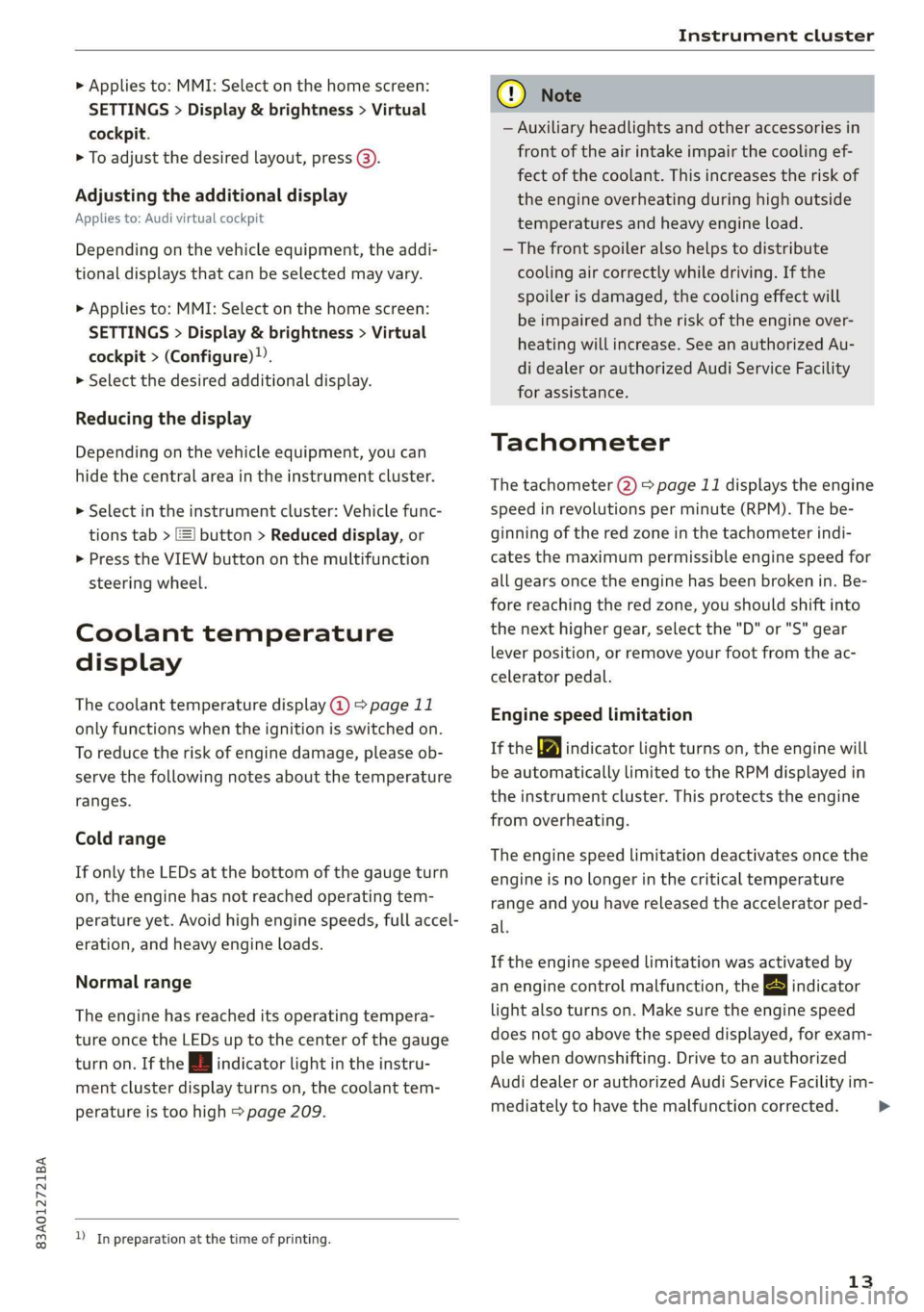
The coolant temperature display @) > page 11
only functions when the ignition is switched on.
To reduce the risk of engine damage, please ob-
serve the following notes about the temperature
ranges.
Cold range
If only the LEDs at the bottom of the gauge turn
on, the engine has not reached operating tem-
perature yet. Avoid high engine speeds, full accel-
eration, and heavy engine loads.
Normal range
The engine has reached its operating tempera-
ture once the LEDs up to the center of the gauge
turn on. If the i | indicator light in the instru-
ment cluster display turns on, the coolant tem-
perature is too high > page 209.
) In preparation at the time of printing.
CG) Note
— Auxiliary headlights and other accessories in
front of the air intake impair the cooling ef-
fect of the coolant. This increases the risk of
the engine overheating during high outside
temperatures and heavy engine load.
—The front spoiler also helps to distribute
cooling air correctly while driving. If the
spoiler is damaged, the cooling effect will
be impaired and the risk of the engine over-
heating will increase. See an authorized Au-
di dealer or authorized Audi Service Facility
for assistance.
Tachometer
The tachometer 2) > page 11 displays the engine
speed in revolutions per minute (RPM). The be-
ginning of the red zone in the tachometer indi-
cates the maximum permissible engine speed for
all gears once the engine has been broken in. Be-
fore reaching the red zone, you should shift into
the next higher gear, select the "D" or "S" gear
lever position, or remove your foot from the ac-
celerator pedal.
Engine speed limitation
If the Ay indicator light turns on, the engine will
be automatically limited to the RPM displayed in
the instrument cluster. This protects the engine
from overheating.
The engine speed limitation deactivates once the
engine is no longer in the critical temperature
range and you have released the accelerator ped-
al.
If the engine speed limitation was activated by
an engine control malfunction, the By indicator
light also turns on. Make sure the engine speed
does not go above the speed displayed, for exam-
ple when downshifting. Drive to an authorized
Audi dealer or authorized Audi Service Facility im-
mediately to have the malfunction corrected.
13
>
Page 16 of 280
Instrument cluster
@) Note
The tachometer needle should only be in the
red zone briefly: Otherwise, this increases the
risk of engine damage. The location where the
red zone begins varies depending on the en-
gine.
Odometer
The trip odometer and odometer are displayed in
the status line ©) > page 11.
The trip odometer shows the distance driven
since it was last reset. It can be used to measure
short distances. The odometer shows the total
distance that the vehicle has been driven.
Resetting the trip odometer
> Select in the instrument cluster: Vehicle func-
tions tab > [=] button > Reset mi.
@) Tips
Distances are displayed in mi (miles) or km
(kilometers).
Outside temperature
display
The outside temperature is displayed in the sta-
tus line @) > page 11.
If your vehicle is stationary or if you are driving at
very low speeds, the temperature displayed in
the instrument cluster may be slightly higher
than the actual temperature outside due to heat
radiating from the engine.
At temperatures below 41 °F (+5 °C), a snowflake
symbol appears in front of the temperature dis-
play > A.
ZA\ WARNING
Do not assume the roads are free of ice based
on the outside temperature display. Be aware
that there may be ice on roads even when the
outside temperature is around 41 °F (+5 °C)
and that ice can increase the risk of accidents.
14
Vehicle functions
The trip computer is displayed in the first tab of
the driver information system. Additional vehicle
functions can be accessed depending on the vehi-
cle equipment.
> Press the =] button on the multifunction steer-
ing wheel.
— On-board computer > page 14
— Reduced display > page 13
— Reset trip odometer > page 14
On-board computer
Resetting values to zero
Requirement: the Consumption, Short-term
memory, or Long-term memory display must be
selected.
> To reset the values in one of the memories to
zero, press and hold the left thumbwheel on
the multifunction steering wheel for one sec-
ond, or
> Select in the instrument cluster: Vehicle func-
tions tab > [=] button > Reset mi.
Depending on the vehicle equipment, you can call
up the following displays in the on-board com-
puter one at a time by turning the left thumb-
wheel on the multifunction steering wheel:
— Time and date > page 195
— Average consumption > page 15
— Short-term memory overview
— Long-term memory overview
— Energy consumers > page 15
— Driver assistance
Short-term memory and long-term memory
The short-term memory collects driving informa-
tion from the time the ignition is switched on un-
tilit is switched off. If you continue driving within
two hours after switching the ignition off, the
new values will be included when calculating the
current trip information.
Page 17 of 280
83A012721BA
Instrument cluster
Unlike the short-term memory, the long-term
memory is not erased automatically. You can se-
lect the time period for evaluating trip informa-
tion yourself.
Average consumption
The current consumption can be shown using a
bar graph. The average consumption stored in
the short-term memory is also displayed. If the
bar is green, your vehicle is saving fuel (for exam-
ple, using recuperation).
Energy consumers
The Energy consumers view lists other equip-
ment that is currently affecting fuel consump-
tion. The display shows up to three equipment
items. The equipment using the most power is
listed first. If more than three items using power
are switched on, the equipment that is currently
using the most power is displayed. A gauge also
shows the current total consumption of all other
equipment.
@) Tips
The date, time of day, and time and date for-
mat can be set > page 195.
15
Page 18 of 280
Touch display
Touch displa Pressing and pulli
General touch display
operation
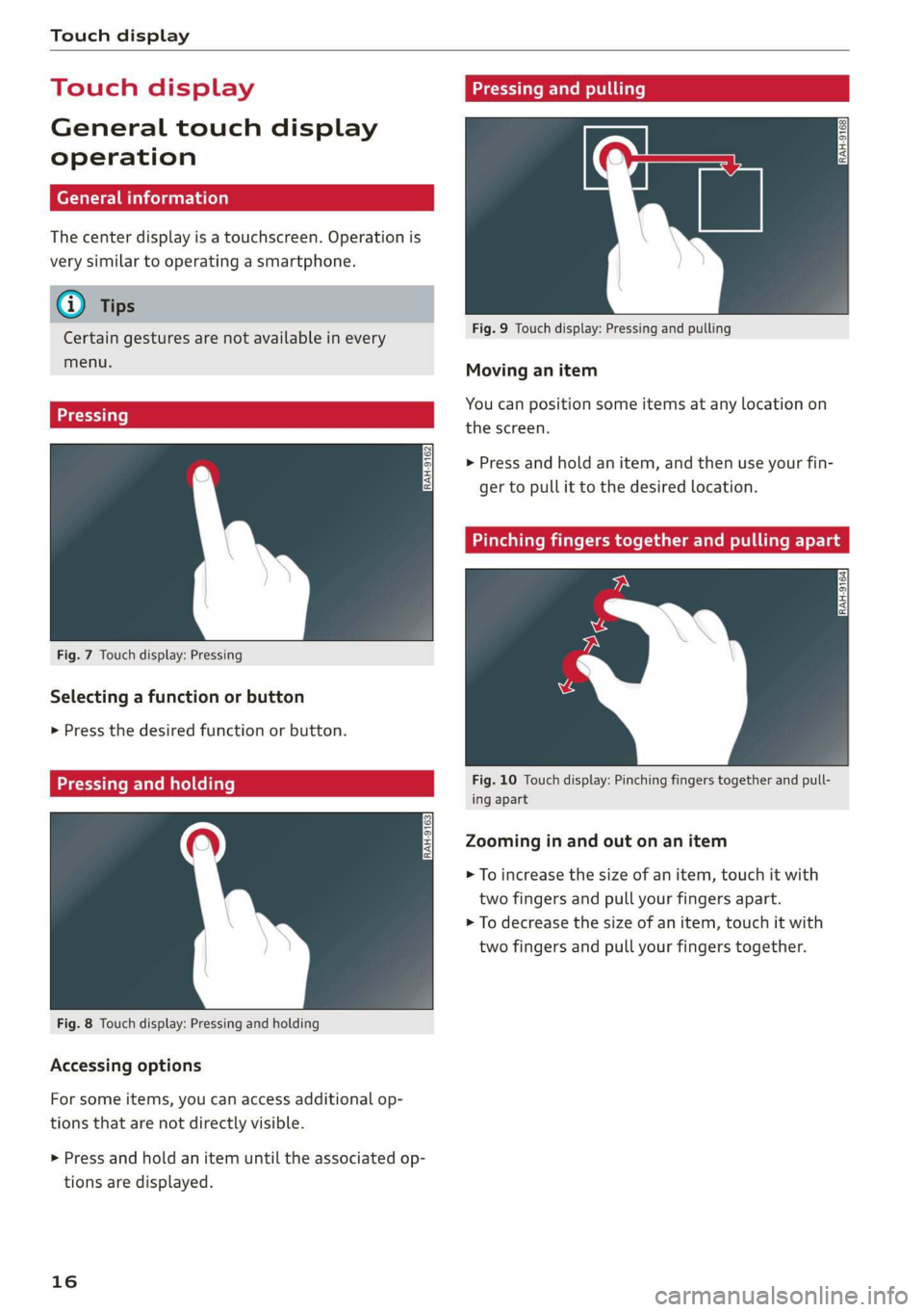
The center display is a touchscreen. Operation is
very similar to operating a smartphone.
@) Tips
Certain gestures are not available in every
menu.
Fig. 9 Touch display: Pressing and pulling
Moving an item
You can position some items at any location on
Eee Soke . the screen.
> Press and hold an item, and then use your fin-
ger to pull it to the desired location.
Fig. 7 Touch display: Pressing
Selecting a function or button
> Press the desired function or button.
relat: Fig. 10 Touch display: Pinching fingers together and pull-
— ing apart
Zooming in and out on an item
> To increase the size of an item, touch it with
two fingers and pull your fingers apart.
> To decrease the size of an item, touch it with
two fingers and pull your fingers together.
Fig. 8 Touch display: Pressing and holding
Accessing options
For some items, you can access additional op-
tions that are not directly visible.
> Press and hold an item until the associated op-
tions are displayed.
16