brake pads CHERY TIGGO 2009 Service Repair Manual
[x] Cancel search | Manufacturer: CHERY, Model Year: 2009, Model line: TIGGO, Model: CHERY TIGGO 2009Pages: 1903, PDF Size: 33.38 MB
Page 1396 of 1903

Downloaded from www.Manualslib.com manuals search engine BRAKES
12
CONTENTSpage
Base Brakes ........................................................................\
. 12-1
Antilock Brakes ..................................................................... 12-34
Parking Brake ...................................................................... 12-79
BASE BRAKES
GENERAL INFORMATION12-2
Description 12-2
Operation 12-3
Specifications 12-4
Special Tools 12-5
Electrical Schematics 12-6
DIAGNOSIS & TESTING12-7
Diagnostic Help 12-7
Brake Noise 12-7
Braking Concerns 12-8
ON-VEHICLE SERVICE12-9
Brake Bleeding 12-9
Brake Bleeding Information 12-9
Brake Bleeding Procedure 12-9
Manual Brake Bleeding 12-9
Pressure Brake Bleeding 12-10
Master Cylinder - LHD 12-11
Description 12-11
Operation 12-11
Removal & Installation 12-11
Master Cylinder - RHD 12-12
Description 12-12
Operation 12-13
Removal & Installation 12-13
Power Brake Booster - LHD 12-14
Description 12-14
Operation 12-14
Removal & Installation 12-14
Power Brake Booster - RHD 12-16
Description 12-16
Operation 12-16
Removal & Installation 12-16Front Brake Caliper
12-18
Description 12-18
Operation 12-18
Removal & Installation 12-19
Rear Brake Caliper 12-19
Description 12-19
Operation 12-20
Removal & Installation 12-20
Front Brake Rotor 12-21
Removal & Installation 12-21
Inspection 12-21
Rear Brake Rotor 12-22
Removal & Installation 12-22
Inspection 12-22
Rear Brake Backing Plate 12-23
Removal & Installation 12-23
Front Brake Pads 12-24
Removal & Installation 12-24
Inspection 12-25
Rear Brake Pads 12-25
Removal & Installation 12-25
Inspection 12-26
UNIT REPAIR12-27
Front Brake Caliper 12-27
Disassemble 12-27
Inspection 12-28
Assemble 12-28
Rear Brake Caliper 12-30
Disassemble 12-30
Inspection 12-31
Assemble 12-32
12
12–1Chery Automobile Co., Ltd.
Page 1397 of 1903

Downloaded from www.Manualslib.com manuals search engine GENERAL INFORMATION
Description
Base Brakes
The base brake system consists of the following components:
•Brake pedal
• Power brake booster
• Master cylinder
• Brake tubes and hoses
• Disc brakes (front)
• Disc brakes (rear)
• Parking brake
• Parking brake shoes (rear)
Front Disc Brake
The front disc brake assembly consists of the following major components:
•Caliper
• Caliper adapter bracket
• Brake pads
• Rotor
1 - Front Wheel Knuckle
2 - Knuckle Hub Bearing
3 - Front Wheel Hub Assembly
4 - Dust Shield5 - Front Brake Rotor
6 - Brake Caliper Assembly
7 - Disc Brake Caliper and Rotor Assembly
LTSM120001
12–2Chery Automobile Co., Ltd.
Page 1398 of 1903

Downloaded from www.Manualslib.com manuals search engine Rear Disc Brake
The rear disc brake assembly consists of the following major components:
•Caliper
• Caliper adapter bracket
• Brake pads
• Rotor
• Parking brake shoes
CAUTION:
•Use DOT 4 brake fluid or equivalent from a tightly sealed container. Do not use petroleum-based
fluids, which will cause seal damage in the brake system.
• Brake fluid will damage painted surfaces. If brake fluid is spilled on any painted surfaces, wash
it off immediately with water.
• Never use gasoline, kerosene, alcohol, motor oil, transmission fluid, or any fluid containing min-
eral oil to clean system components. These fluids damage rubber cups and seals.
• During service procedures, grease or any other foreign material must be kept off the caliper
assembly, brake pads, brake rotor and external surfaces of the hub.
• When handling the brake rotor and caliper, be careful to avoid damaging the brake rotor and
caliper, and scratching or nicking the brake shoe lining.
Operation
Applying the brake pedal uses lever action to push a rod into the brake booster, which through the use of vacuum,
boosts the force of the rod and then transmits this force into the master cylinder. This produces hydraulic pressure in
the master cylinder. On vehicles not equipped with ABS, the hydraulic pressure is transmitted by brake fluid through
the brake tubes to the individual brake calipers or wheel cylinders. On vehicles equipped with ABS, the hydraulic
pressure is transmitted by brake fluid through the brake tubes to the ABS hydraulic control unit (HCU), which then
distributes that pressure to the individual brake calipers and wheel cylinders. The brake calipers use hydraulic pres-
sure to apply the brake pads. The application of the brake pads or shoes will cause the rotation of the wheels to slow
or stop depending on how much brake pressure is applied. The parking brakes carry out the same function except
that they are mechanically actuated by a cable that connects only to the rear brakes.
1 - Rear Hub Mounting Assembly
2 - Rear Brake Assembly
3 - Lock Nut
4 - Rear Wheel Hub Bearing Unit5 - Rear Brake Rotor
6 - Caliper Bolts
7 - Brake Caliper Assembly
7 - Disc Brake Caliper and Rotor Assembly
GENERAL INFORMATION
LTSM120002
12
12–3Chery Automobile Co., Ltd.
Page 1402 of 1903
Downloaded from www.Manualslib.com manuals search engine DIAGNOSIS & TESTING
Diagnostic Help
Brake diagnosis involves determining if the concern is related to a mechanical, hydraulic, electrical or vacuum oper-
ated component.
NOTE :
The brake reservoir fluid level will decrease in proportion to normal lining wear.
NOTE :
Brake fluid tends to darken over time. This is normal and should not be mistaken for contamination.
Preliminary Brake Check:
•Check the condition of the tires and wheels. Damaged wheels and worn, damaged or under inflated tires can
cause a pull, shudder, vibration and a condition similar to brake grab.
• If a complaint was based on noise while braking, check the suspension components. Jounce the front and the
rear of vehicle and listen for anything that might be caused by a loose, worn or damaged suspension or steer-
ing component.
• Inspect the brake fluid level and condition.
1. If the fluid level is abnormally low, look for any evidence of leaks at the calipers, brake lines, master cyl-
inder and at the Antilock Brake System (ABS) Hydraulic Control Unit (HCU).
2. If the fluid appears to be contaminated, drain a sample to examine.
• The system will have to be flushed if the fluid is separated into layers, or contains a substance other than
brake fluid. The system seals, cups, hoses, master cylinder and HCU will also have to be replaced after flush-
ing. Use clean brake fluid to flush the system.
• Check the parking brake operation. Verify free movement and full release of the cables and the lever. Also note
if the vehicle was being operated with the parking brake partially applied.
• Check the brake pedal operation. Verify that the pedal does not bind and has adequate free play. If the pedal
lacks free play, check the pedal and the power booster for looseness or for a binding condition. DO NOT road
test the vehicle until the condition is located and corrected.
• Check the vacuum booster check valve and vacuum supply hose.
• If the preliminary checks appear to be OK, road test the vehicle.
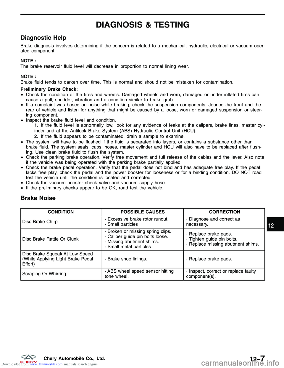
Brake Noise
CONDITION POSSIBLE CAUSES CORRECTION
Disc Brake Chirp · Excessive brake rotor runout.
· Small particles· Diagnose and correct as
necessary.
Disc Brake Rattle Or Clunk · Broken or missing spring clips.
· Caliper guide pin bolts loose.
· Missing abutment shims.
· Small metal particles· Replace brake pads.
· Tighten guide pin bolts.
· Replace missing abutment shims.
Disc Brake Squeak At Low Speed
(While Applying Light Brake Pedal
Effort) · Brake shoe linings.
· Replace brake pads.
Scraping Or Whirring · ABS wheel speed sensor hitting
tone wheel.· Inspect, correct or replace faulty
component(s).
12
12–7Chery Automobile Co., Ltd.
Page 1403 of 1903

Downloaded from www.Manualslib.com manuals search engine Braking Concerns
CONDITIONPOSSIBLE CAUSES CORRECTION
Excessive Pedal Effort · Obstruction of brake pedal.
· Low power brake booster assist.
· Glazed brake pads.
· Brake pad lining transfer to brake
rotor.· Inspect, remove or move
obstruction.
· Refer to Power Brake Booster in
this section.
· Resurface or replace brake rotors
as necessary. Replace brake pads.
· Resurface or replace brake rotors
as necessary. Replace brake pads.
Excessive Pedal Effort (Hard Pedal
Unable To Lock-Up Wheels) · Power brake booster runout
(vacuum assist).· Check booster vacuum hose and
engine tune for adequate vacuum
supply.
Excessive Pedal Travel (Vehicle
Stops OK) · Air in brake lines.
· Bleed brakes.
Pedal Pulsates/Surges During
Braking · Disc brake rotor has excessive
thickness variation.· Isolate condition as rear or front.
Resurface or replace brake rotors as
necessary.
Pedal Is Spongy · Air in brake lines.· Bleed brakes.
Vehicle Pulls To Right Or Left On
Braking · Frozen brake caliper piston.
· Contaminated brake pad/shoe
lining (most likely front lining).
· Pinched brake lines.
· Leaking piston seal.
· Suspension problem.· Replace frozen piston or caliper.
Bleed brakes.
· Inspect and clean, or replace
pads/shoes. Repair source of
contamination.
· Replace pinched line.
· Replace piston seal or brake
caliper.
· See the Suspension section.
Parking Brake - Excessive Handle
Travel · Rear brakes out of adjustment.· Adjust rear parking brake shoes on
vehicles with rear disc brakes.
DIAGNOSIS & TESTING
12–8Chery Automobile Co., Ltd.
Page 1416 of 1903
Downloaded from www.Manualslib.com manuals search engine Front Brake Rotor
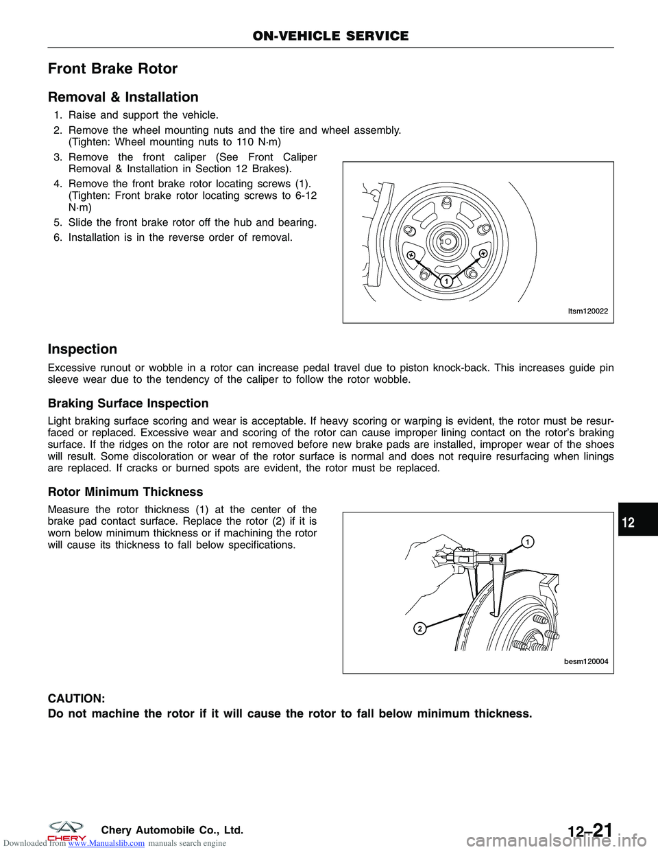
Removal & Installation
1. Raise and support the vehicle.
2. Remove the wheel mounting nuts and the tire and wheel assembly.(Tighten: Wheel mounting nuts to 110 N·m)
3. Remove the front caliper (See Front Caliper Removal & Installation in Section 12 Brakes).
4. Remove the front brake rotor locating screws (1). (Tighten: Front brake rotor locating screws to 6-12
N·m)
5. Slide the front brake rotor off the hub and bearing.
6. Installation is in the reverse order of removal.
Inspection
Excessive runout or wobble in a rotor can increase pedal travel due to piston knock-back. This increases guide pin
sleeve wear due to the tendency of the caliper to follow the rotor wobble.
Braking Surface Inspection
Light braking surface scoring and wear is acceptable. If heavy scoring or warping is evident, the rotor must be resur-
faced or replaced. Excessive wear and scoring of the rotor can cause improper lining contact on the rotor’s braking
surface. If the ridges on the rotor are not removed before new brake pads are installed, improper wear of the shoes
will result. Some discoloration or wear of the rotor surface is normal and does not require resurfacing when linings
are replaced. If cracks or burned spots are evident, the rotor must be replaced.
Rotor Minimum Thickness
Measure the rotor thickness (1) at the center of the
brake pad contact surface. Replace the rotor (2) if it is
worn below minimum thickness or if machining the rotor
will cause its thickness to fall below specifications.
CAUTION:
Do not machine the rotor if it will cause the rotor to fall below minimum thickness.
ON-VEHICLE SERVICE
LTSM120022
BESM120004
12
12–21Chery Automobile Co., Ltd.
Page 1417 of 1903
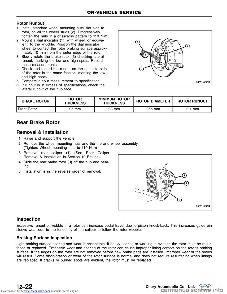
Downloaded from www.Manualslib.com manuals search engine Rotor Runout
1. Install standard wheel mounting nuts, flat side torotor, on all the wheel studs (2). Progressively
tighten the nuts in a crisscross pattern to 110 N·m.
2. Mount a dial indicator (1), with wheel, or equiva- lent, to the knuckle. Position the dial indicator
wheel to contact the rotor braking surface approxi-
mately 10 mm from the outer edge of the rotor.
3. Slowly rotate the brake rotor (3) checking lateral runout, marking the low and high spots. Record
these measurements.
4. Check and record the runout on the opposite side of the rotor in the same fashion, marking the low
and high spots.
5. Compare runout measurement to specification.
6. If runout is in excess of specifications, check the lateral runout of the hub face.
BRAKE ROTOR ROTOR
THICKNESS MINIMUM ROTOR
THICKNESS ROTOR DIAMETER ROTOR RUNOUT
Front Rotor 25 mm23 mm265 mm 0.1 mm
Rear Brake Rotor
Removal & Installation
1. Raise and support the vehicle.
2. Remove the wheel mounting nuts and the tire and wheel assembly.
(Tighten: Wheel mounting nuts to 110 N·m)
3. Remove rear caliper (1) (See Rear Caliper Removal & Installation in Section 12 Brakes).
4. Slide the rear brake rotor (3) off the hub and bear- ing.
5. Installation is in the reverse order of removal.
Inspection
Excessive runout or wobble in a rotor can increase pedal travel due to piston knock-back. This increases guide pin
sleeve wear due to the tendency of the caliper to follow the rotor wobble.
Braking Surface Inspection
Light braking surface scoring and wear is acceptable. If heavy scoring or warping is evident, the rotor must be resur-
faced or replaced. Excessive wear and scoring of the rotor can cause improper lining contact on the rotor’s braking
surface. If the ridges on the rotor are not removed before new brake pads are installed, improper wear of the shoes
will result. Some discoloration or wear of the rotor surface is normal and does not require resurfacing when linings
are replaced. If cracks or burned spots are evident, the rotor must be replaced.
ON-VEHICLE SERVICE
LTSM120042
LTSM120043
12–22Chery Automobile Co., Ltd.
Page 1419 of 1903
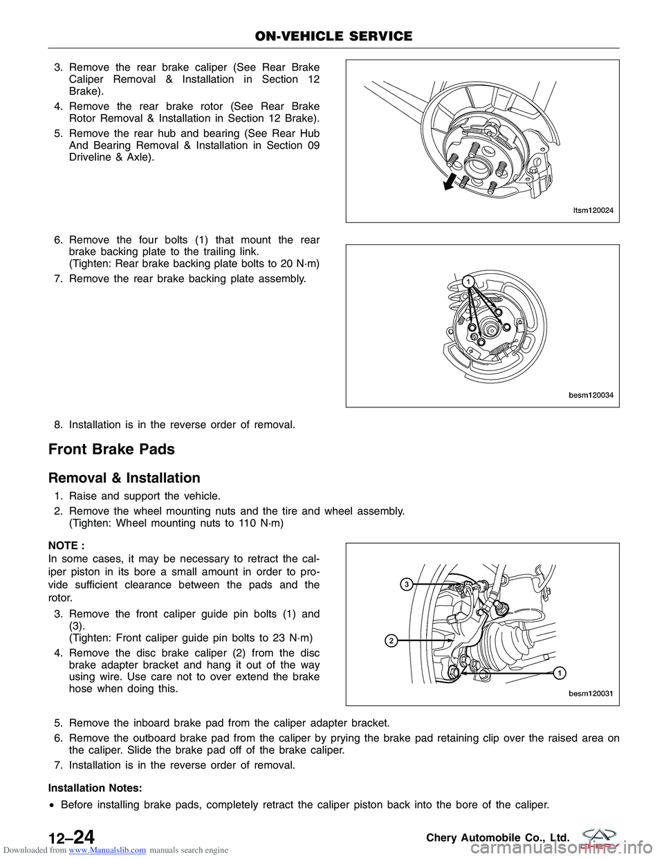
Downloaded from www.Manualslib.com manuals search engine 3. Remove the rear brake caliper (See Rear BrakeCaliper Removal & Installation in Section 12
Brake).
4. Remove the rear brake rotor (See Rear Brake Rotor Removal & Installation in Section 12 Brake).
5. Remove the rear hub and bearing (See Rear Hub And Bearing Removal & Installation in Section 09
Driveline & Axle).
6. Remove the four bolts (1) that mount the rear brake backing plate to the trailing link.
(Tighten: Rear brake backing plate bolts to 20 N·m)
7. Remove the rear brake backing plate assembly.
8. Installation is in the reverse order of removal.
Front Brake Pads
Removal & Installation
1. Raise and support the vehicle.
2. Remove the wheel mounting nuts and the tire and wheel assembly. (Tighten: Wheel mounting nuts to 110 N·m)
NOTE :
In some cases, it may be necessary to retract the cal-
iper piston in its bore a small amount in order to pro-
vide sufficient clearance between the pads and the
rotor. 3. Remove the front caliper guide pin bolts (1) and (3).
(Tighten: Front caliper guide pin bolts to 23 N·m)
4. Remove the disc brake caliper (2) from the disc brake adapter bracket and hang it out of the way
using wire. Use care not to over extend the brake
hose when doing this.
5. Remove the inboard brake pad from the caliper adapter bracket.
6. Remove the outboard brake pad from the caliper by prying the brake pad retaining clip over the raised area on the caliper. Slide the brake pad off of the brake caliper.
7. Installation is in the reverse order of removal.
Installation Notes:
• Before installing brake pads, completely retract the caliper piston back into the bore of the caliper.
ON-VEHICLE SERVICE
LTSM120024
BESM120034
BESM120031
12–24Chery Automobile Co., Ltd.
Page 1420 of 1903
Downloaded from www.Manualslib.com manuals search engine •After installation and before moving the vehicle, pump the brake pedal several times to set the pads to the
brake rotor.
• Check and adjust the brake fluid level in the reservoir as necessary.
• Road test the vehicle and make several stops to wear off any foreign material on the brakes and to seat the
brake pads.
• After installation and before moving the vehicle, pump the brake pedal several times to set the pads to the
brake rotor.
Inspection
Visually inspect brake pads for uneven lining wear. Also inspect for excessive lining deterioration. Check the clear-
ance between the tips of the wear indicators (if equipped) on the pads and the brake rotors. If a visual inspection
does not adequately determine the condition of the lining, a physical check will be necessary. To check the amount
of lining wear, remove the disc brake pads from the vehicle. Measure the brake pad minimum thickness. Brake pads
must be replaced when usable material on a brake pad lining measured at its thinnest point measures one millimeter
or less. Replace both disc brake pads (inboard and outboard) at each caliper. It is also necessary to replace the pads
on the opposite side of the vehicle as well as the pads failing inspection to maintain proper braking characteristics.
If the brake pad assemblies do not require replacement, be sure to reinstall the brake pads in the original position
from which they were removed.
Rear Brake Pads
Removal & Installation
1. Raise and support the vehicle.
2. Remove the wheel mounting nuts and the tire and wheel assembly.
(Tighten: Wheel mounting nuts to 110 N·m)
NOTE :
In some cases, it may be necessary to retract the caliper piston in its bore a small amount in order to provide suf-
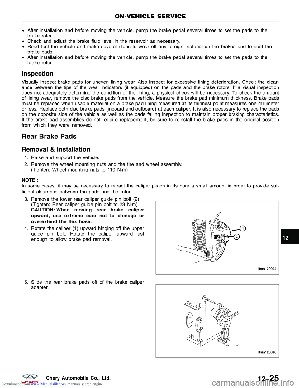
ficient clearance between the pads and the rotor. 3. Remove the lower rear caliper guide pin bolt (2). (Tighten: Rear caliper guide pin bolt to 23 N·m)
CAUTION: When moving rear brake caliper
upward, use extreme care not to damage or
overextend the flex hose.
4. Rotate the caliper (1) upward hinging off the upper guide pin bolt. Rotate the caliper upward just
enough to allow brake pad removal.
5. Slide the rear brake pads off of the brake caliper adapter.
ON-VEHICLE SERVICE
LTSM120044
LTSM120018
12
12–25Chery Automobile Co., Ltd.
Page 1421 of 1903

Downloaded from www.Manualslib.com manuals search engine Inspection
Visually inspect brake pads for uneven lining wear. Also inspect for excessive lining deterioration. Check the clear-
ance between the tips of the wear indicators (if equipped) on the pads and the brake rotors. If a visual inspection
does not adequately determine the condition of the lining, a physical check will be necessary. To check the amount
of lining wear, remove the disc brake pads from the vehicle. Measure the brake pad minimum thickness. Brake pads
must be replaced when usable material on a brake pad lining measured at its thinnest point measures one millimeter
or less. Replace both disc brake pads (inboard and outboard) at each caliper. It is also necessary to replace the pads
on the opposite side of the vehicle as well as the pads failing inspection to maintain proper braking characteristics.
If the brake pad assemblies do not require replacement, be sure to reinstall the brake pads in the original position
from which they were removed.
ON-VEHICLE SERVICE
12–26Chery Automobile Co., Ltd.