change wheel CHEVROLET CAMARO 1967 1.G Chassis Workshop Manual
[x] Cancel search | Manufacturer: CHEVROLET, Model Year: 1967, Model line: CAMARO, Model: CHEVROLET CAMARO 1967 1.GPages: 659, PDF Size: 114.24 MB
Page 15 of 659
LUBRICATION 0-13
LUBRICATION
INDEX
Page
Engine Crankcase Oil . 0-13
Crankcase Capacities. . 0-13
Lubrication . ,
•
o-13
SAE Viscosity Oils 0-13
Types of Oils 0-14
Maintaining Oil Level 0-14
Oil and Filter Change Intervals 0-14
Oil.
. . ...:.. 0-14
Filter o-14
Crankcase Dilution . 0-14
Automatic Control Devices to Minimize
Crankcase Dilution 0-14
Crankcase Breather Cap 0-14
Crankcase Ventilation System 0-15
Valve Type 0-15
Fuel Filter 0-15
Air Cleaner . 0-15
Polyurethane Type 0-15
Oil Wetted Paper Element Type 0-15
Battery Terminal Washers 0-15
Page
Distributor 0-15
Rear Axle and 3-Speed and Overdrive
4-Speed Transmission 0-15
Recommended Lubricants 0-15
Multi-Purpose Gear Lubricants 0-15
Lubricant Additions 0-15
Lubricant Changes 0-15
Powerglide Transmission 0-15
Turbo Hydra-Matic 0-16
Front Wheel Bearings 0-16
Manual Steering Gear . . . . 0-16
Power Steering 0-16
Air Conditioning 0-16
Brake Master Cylinder. 0-16
Parking Brake 0-16
Clutch Cross-Shaft , 0-16
Chassis Lubrication 0-16
Lubrication Diagrams . . 0-19
Body Lubrication (Chevrolet, Chevelle, Chevy n, Camaro). 0-20
Body Lubrication Points (Corvette) . 0-21
The selection of the proper lubricant and its correct
application at regular intervals does much to increase the
life and operation of all moving parts of the vehicle.
Consequently, it is important that the correct grade of
oil or grease, as noted in the following pages, be used.
ENGINE CRANKCASE OIL
Crankcase Capacity
4 Cylinder 4 qt.
6 Cylinder 4 qt.
8 Cylinder (283) 4 qt.
8 Cylinder (327) 4 qt.
8 Cylinder (350) 4 qt.
8 Cylinder (396) 4 qt.
8 Cylinder (427) Chevrolet 4 qt.
8 Cylinder (427) Corvette 5 qt.
For 4 Cyl. Add .5 qt. with filter change;
1 qt. for 6 and 8 Cyl. engines.
Lubrication
Crankcase oil should be selected to give the best per-
formance under the climatic and driving conditions in the
territory in which the vehicle is driven.
During warm or hot weather, an oil which will provide
adequate lubrication under high operating temperatures
is required.
During the colder months of the year* an oil which will
permit easy starting at the lowest atmospheric tempera-
ture likely to be encountered, should be used.
When the crankcase is drained and refilled, the crank-
case oil should be selected, not on the basis of the exist-
ing temperature at the time of the change, but on the
lowest temperature anticipated for the period during
which the oil is to be used.
Unless the crankcase oil is selected on the basis of
viscosity or fluidity of the anticipated temperature, dif-
ficulty in starting will be experienced at each sudden
drop in temperature.
SAE Viscosity Oils
SAE Viscosity Numbers indicate only the viscosity or
body of the oil, that is, whether an oil is a light or a
heavy body oil, and do not consider or include other
properties or quality factors.
The lower SAE Viscosity Numbers, such as SAE 5W
and SAE 10W which represent the light body oils, are
recommended for use during cold weather to provide
easy starting and instant lubrication. The higher SAE
Viscosity Numbers such as SAE 20 and SAE 20W, which
represents heavier body oils, are recommended for use
during warm or hot weather to provide improved oil
economy and adequate lubrication under high operating
temperatures.
Oils are available which are designed to combine the
easy starting characteristics of the lower SAE Viscosity
Number with the warm weather operating characteristics
of the higher SAE Viscosity Number. These are termed
"multi-viscosity oils," SAE 5-10W, SAE 5W-20, SAE
10W-20W, and SAE 10W-30.
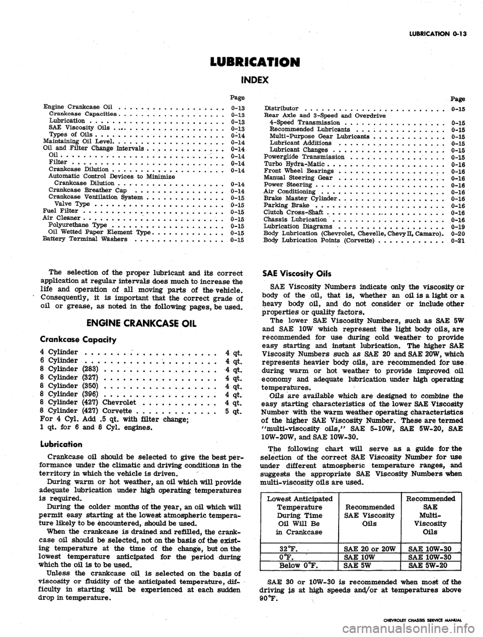
The following chart will serve as a guide for the
selection of the correct SAE Viscosity Number for use
under different atmospheric temperature ranges, and
suggests the appropriate SAE Viscosity Numbers when
multi-viscosity oils are used.
Lowest Anticipated
Temperature
During Time
Oil Will Be
in Crankcase
32°F.
0°F.
Below 0°F.
Recommended
SAE Viscosity
Oils
SAE 20 or 20W
SAE 10W
SAE 5W
Recommended
SAE
Multi-
Viscosity
Oils
SAE 10W-30 .
SAE 10W-30
SAE 5W-20
SAE 30 or 10W-30 is recommended when most of the
driving is at high speeds and/or at temperatures above
90
°F.
CHEVROLET CHASSIS SERVICE MANUAL
Page 18 of 659
LUBRICATION 0-16
Every 12,000 miles (more frequently*, depending on
severity of service, if vehicle is used to pull trailers,
carry full loads during high ambient temperatures,
operate in mountainous terrain or operate under other
severe conditions--Remove fluid from the transmission
sump and add one and a half quarts of fresh fluid for
Camaro and Chevy II and two quarts for Chevrolet,
Chevelle, and Corvette. Operate transmission through all
ranges and check fluid level as described above.
•Except if vehicle is equipped with transmission pro-
vided in heavy duty service options. If so equipped,
drain converter and pump every 12,000 miles and add
approximately seven and a half quarts of fresh fluid
for Chevy II and nine quarts for Chevrolet and Chevelle.
TURBO HYDRA-MATIC
Lubrication. recommendations for the Turbo Hydra-
Matic are the same as outlined for the Powerglide
transmission except for fluid capacity and filter change
listed below.
After checking transmission fluid level it is important
that the dip stick be pushed all the way into the fill tube.
Every 12,000 miles — after removing fluid from the
transmission sump, approximately 7 1/2 pints of fresh
fluid will be required to return level to proper mark on
the dip stick.
Every 24,000 miles, or at every other fluid change--
the transmission sump strainer should be replaced.
FRONT WHEEL BEARINGS
It is necessary to remove the wheel and hub assembly
to lubricate the bearings. The bearing assemblies should
be cleaned before repacking with lubricant. Do not pack
the hub between the inner and outer bearing assemblies
or the hub caps, as this excessive lubrication results in
the lubricant working out into the brake drums and
linings.
Front wheels of all passenger car models are equipped
with tapered roller bearings and should be packed with a
high melting point water resistant front wheel bearing
lubricant whenever wheel and hub are removed.
CAUTION: "Long fibre" or "viscous" type
lubricant should not be used. Do not mix wheel
bearing lubricants. Be sure to thoroughly clean
bearings and hubs of all old lubricant before
repacking.
The proper adjustment of front wheel bearings is one
of the important service operations- that has a definite
bearing on safety. A car with improperly adjusted front
wheel bearings lacks steering stability, has a tendency to
wander or shimmy and may have increased tire wear.
The adjustment of these bearings is very critical. The
procedure is covered in Section 3 of this manual under
Front Wheel Bearings—Adjust,
MANUAL STEERING GEAR
Check lubricant level every 36,000 miles. If required,
add EP Chassis Lubricant.
POWER STEERING
On models equipped with power steering gear, check
fluid at operating temperature in pump reservoir. Add
GM Power Steering Fluid, or, if this is not available, use
Automatic Transmission Fluid "Type A" bearing the
mark AQ-ATF followed by a number and the suffix letter
'A'
to bring level to full mark on dip stick.
AIR CONDITIONING
After the first 6,000 miles, check all hose clamp
connections for proper tightness.
Every 6,000 miles check sight glass under the hood,
after the system has been in operation for several
minutes. Sight glass should be clear but may, during
milder weather, show traces of bubbles. Foam or dirt
indicate a leak which should be repaired immediately.
BRAKE MASTER CYLINDER
Check level every 6,000 miles and maintain 1/4" below
lowest edge of each filler opening with GM Hydraulic
Brake Fluid Supreme No. 11.
PARKING BRAKE
Every 6,000 miles, apply water resistant lube to park-
ing brake cable, cable guides and at all operating links
and levers.
CLUTCH CROSS-SHAFT
Periodic lubrication of the clutch cross shaft is not
required. At 36,000 miles or sooner, if necessary;
remove plug, install lube fitting and apply CHASSIS
LUBRICANT.
CHASSIS LUBRICATION
For chassis lubrication, consult the lubrication chart.
It shows the points to be lubricated and how often the
lubricant should be applied.
The term "chassis lubricant" as used in this manual,
describes a water resistant EP chassis grease designed
for application by commercial pressure gun equipment.
CHEVROLET CHASSIS SERVICE MANUAL
Page 41 of 659
HEATER AND AIR CONDITIONING 1A-18
HIGH BLOWER
i DELAY RELAY
AMBIENT-SUN
SENSOR AND
COMPRESSOR SWITCH
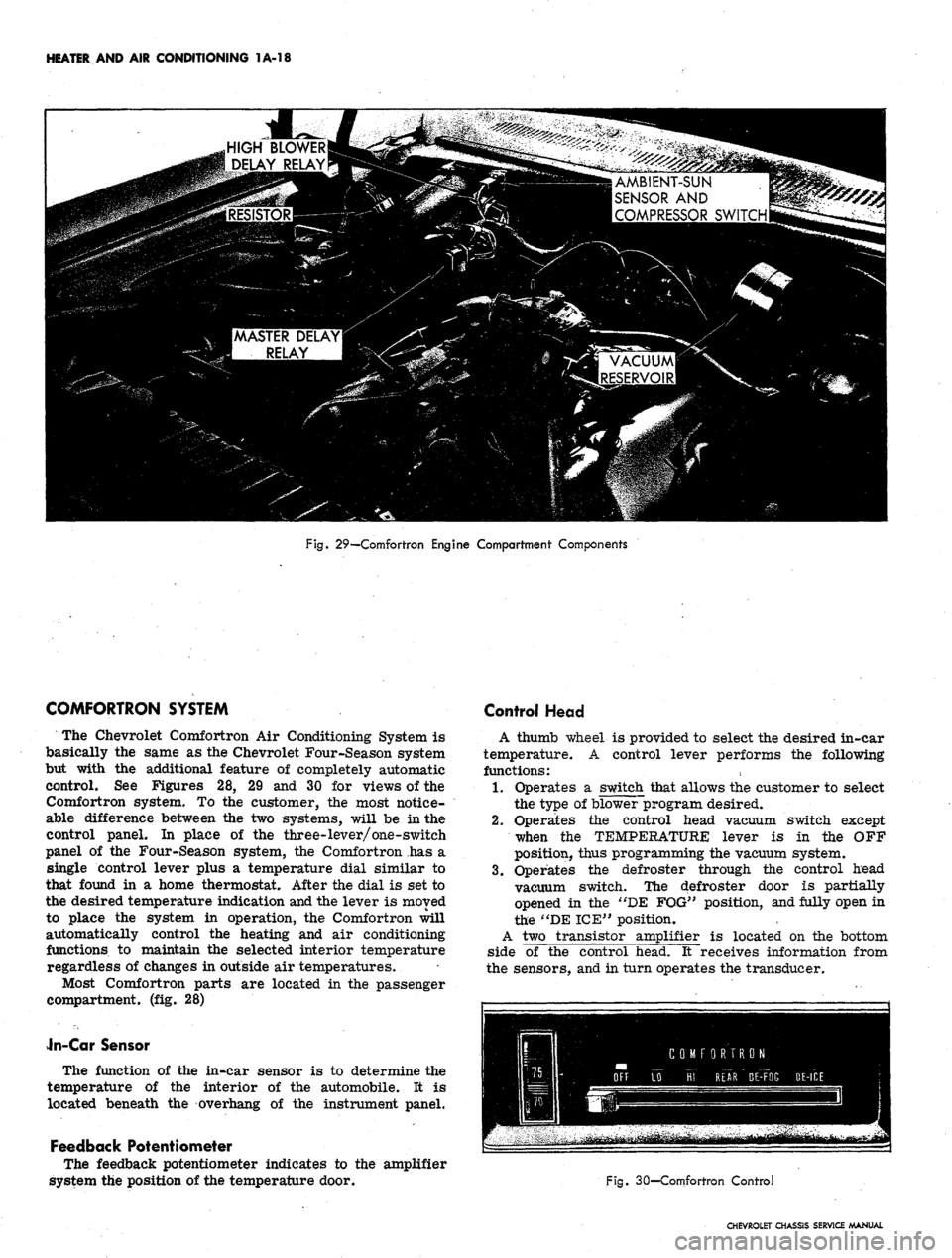
Fig. 29—Comfortron Engine Compartment Components
COMFORTRON SYSTEM
The Chevrolet Comfortron Air Conditioning System is
basically the same as the Chevrolet Four-Season system
but with the additional feature of completely automatic
control. See Figures 28, 29 and 30 for views of the
Comfortron system. To the customer, the most notice-
able difference between the two systems, will be in the
control panel. In place of the three-lever/one-switch
panel of the Four-Season system, the Comfortron has a
single control lever plus a temperature dial similar to
that found in a home thermostat. After the dial is set to
the desired temperature indication and the lever is moved
to place the system in operation, the Comfortron will
automatically control the heating and air conditioning
functions to maintain the selected interior temperature
regardless of changes in outside air temperatures.
Most Comfortron parts are located in the passenger
compartment, (fig. 28)
Jn-Car Sensor
The function of the in-car sensor is to determine the
temperature of the interior of the automobile. It is
located beneath the overhang of the instrument panel.
Feedback Potentiometer
The feedback potentiometer indicates to the amplifier
system the position of the temperature door.
Control Head
A thumb wheel is provided to select the desired in-car
temperature. A control lever performs the following
functions:
1.
Operates a switch that allows the customer to select
the type of blower program desired.
2.
Operates the control head vacuum switch except
when the TEMPERATURE lever is in the OFF
position, thus programming the vacuum system.
3.
Operates the defroster through the control head
vacuum switch. The defroster door is partially
opened in the "DE FOG" position, and fully open in
the "DE ICE" position.
A two transistor amplifier is located on the bottom
side of the control head. It receives information from
the sensors, and in turn operates the transducer.
Fig. 30—Comfortron Control
CHEVROLET CHASSIS SERVICE MANUAL
Page 43 of 659
HEATER AND AIR CONDITIONING 1A-20
and its resistance is decreasing. In the HI FRONT
position, two thermistors (the master delay and high
blower delay thermistors) are warming. The air
door is in recirculation position until the engine
coolant reaches 75 degrees.
2.
The coolant reaches then 75 degrees and the thermal
vacuum valve opens applying vacuum to the air door
to admit outside air (unless the temperature dial is
set for cooling). Ram air will flow through the sys-
tem when the car is moving.
3.
Next, the master delay thermistor attains the tem-
perature at which it will pass sufficient current to
close the circuit through the master delay relay.
The relay circuit powers the blower motor at 9 volts.
4.
If the control is in the HI FRONT position, the high
blower delay thermistor will close the circuit
through the high blower relay which supplies full
available voltage to the blower motor. This function
occurs after the master delay thermistor has taken
effect because the high blower delay thermistor
uses the master delay type thermistor with a 10 ohm
1/4 watt resistor connected in
.
series. The nigh
blower delay thermistor must then warm to a higher
temperature than the master delay thermistor before
its resistance (plus that of the 10 ohm resistor)
drops enough to actuate the high blower relay.
5. If the controls are set for DE ICE, full outside air
and full voltage to the blower motor are effective
immediately regardless of temperatures or elapsed
times o
In accomplishing automatic control, the system follows
three steps to transform an electronic signal into me-
chanical energy through which the control is achieved.
Electronic Circuit
Two temperature sensors (Thermistors), and the duct
potentiometer connected in series, are located so as to
sense the temperature of the outside air, inside air and
system output air. The resistance of each sensor will
vary according to its temperature. The control head
temperature dial varies in resistance as it is adjusted by
the operator to suit his comfort requirements. The
resistance of the temperature dial control is applied
directly to the amplifier and is not in series with the
sensors and duct potentiometer. Thus temperature dif-
ferences in the sensor string plus the requirements fed
into the system by the operator cause changes in total
circuit resistance which allow a varying voltage flow
through the circuit.
Changing the Electronic Signal to Electrical Voltage
This minute voltage flow from the sensor string -
temperature dial circuit - is fed into the amplifier where
it is transformed into a usable amplifier output voltage,
the strength of which is determined by the strength of the
original amplifier input signal. This voltage is then
supplied to the transducer.
Changing the Electrical Voltage to a Vacuum Signal
Amplifier output voltage, varying according to tem-
perature requirements, is converted by the Transducer
into a modulator transducer output vacuum. This modu-
lated vacuum is applied to the Power Servo.
Changing the Vacuum Signal to Mechanical Energy
The Power Servo, controlled by the modulated Trans-
ducer output vacuum, operates the vacuum electrical and
mechanical components of the system as required to
provide automatic control of system operation.
Other major system components are mounted con-
ventionally in the engine compartment. Underhood com-
ponents and system airflow remain much the same as in
the Four-Season system except for the addition of the
automatic control provisions. The system operates on
100%
outside air, a mixture of outside and inside air, or
100%
recirculated air depending on the demands of the
system. The diaphragm operated .air selector door will
modulate outside air to the system during maximum air
conditioning requirements when the control unit is in
"Hi Front" position. Control of the blower is also com-
pletely automatic and dependent upon system demands.
Controls
The Comfortron controls the Chevrolet air conditioner
and heater in such a precise manner that the automobile
temperature remains relatively constant under all driving
conditions. By adjusting the thumb wheel on the Control
Head to any temperature desired between 65° and 85° F.
(See Figure 27) the automatic system will adjust the in-
car temperature even though the outside weather condi-
tions may vary considerably. The system will provide
maximum capacity for heating or cooling until the in-car
temperature reaches the pre-set Control Head Tempera-
ture. Where cooling is required, the system will start
immediately upon being turned "ON". During marginal
ambient temperatures the system will not always start
at the highest blower speeds of the control setting.
Therefore, occasionally the system can't be heard
starting*
Five over-riding functions are available so that special
conditions can be handled. Each Control Head function
will be discussed in detail below:
"Off" Position
In the "Off" position, the blower is turned off and the
outside air door is closed. No outside air should enter
the automobile.
"Lo Front" Position
The blower has five low to moderate speeds; Hi, M3,
M2,
M1 and Lo. The blower voltage will shift as directed
by the automatic controls. The "Lo Front" position
provides a quieter mode of automatic operation due to
reduction of blower noise.
"Hi Front" Position
The "Hi Front" position provides five high blower
speeds as called for by the automatic controls: The use
of the "Hi" blower speed results in a rapid cool down in
hot weather and rapid heating during cold weather. As
the in-car temperature approaches the temperature set-
ting on the Comfortron Control Head, the blower speed
will change, provided mild outside temperatures are
experienced. During very hot or cold weather, the blower
will reduce its speed only to the point where it is still
capable of maintaining the correct inrcar temperature.
"Rear" Position
The "Rear" position provides five high blower speeds.
The automatic controls select these speeds and blend the
discharge air to the proper temperature. By the use of
high blower speeds, increased airflow is obtained for
better rear seat passenger comfort.
CHEVROLET CHASSIS SERVICE MANUAL
Page 169 of 659
FRONT SUSPENSION 3-5
FRONT END ALIGNMENT
Front end alignment, that is alignment of the inter-
related steering components of the front suspension sys-
tem, must be correctly maintained to assure ease and
stability of steering and satisfactory tire life.
Alignment Preliminary Steps
Several different types of machines are available for
checking all the factors of front end alignment. The in-
structions furnished with each particular machine should
be followed. In all cases, however, checks should be
made with the vehicle level and at curb weight.
Since steering complaints are not always the result of
improper alignment a check should be made to see if any
of the following conditions exist. Any such conditions
should be corrected before proceeding further.
1.
Steering gear loose or improperly adjusted.
2.
Steering gear housing loose at frame.
3.
Excessive wear or play in spherical joints or steer-
ing shaft coupling.
4.
Tie rod or steering connections loose.
5.
Improper front spring heights.
6. Unbalanced or underinflated tires.
7.
Improperly adjusted wheel bearings.
8. Shock absorbers not operating properly.
Wheel alignment should always be made with the vehi-
cle rolled forward taking out any slack in the same man-
ner as when the vehicle is traveling forward.
Caster and Camber Adjustment
NOTE: Before adjusting caster and camber
angles, the front bumper should be raised and
quickly released to allow car to return to its
normal height.
Chevelle, Camaro and Corvette
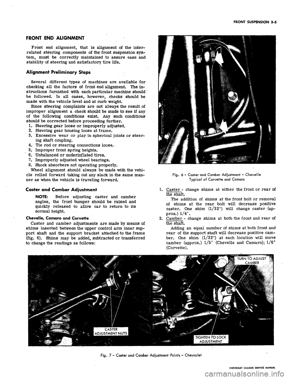
Caster and camber adjustments are made by means of
shims inserted between the upper control arm inner sup-
port shaft and the support bracket attached to the frame
(fig. 6). Shims may be added, subtracted or transferred
to change the readings as follows:
Fig.
6 - Caster and Camber Adjustment - Chevelle
Typical of Corvette and Camaro
Caster - change shims at either the front or rear of
the shaft.
The addition of shims at the front bolt or removal
of shims at the rear bolt will decrease positive
caster. One shim (1/3 2") will change caster (ap-
prox.) 1/4°.
Camber - change shims at both the front and rear of
the shaft.
Adding an equal number of shims at both front and
rear of the support shaft will decrease positive cam-
ber. One shim (1/32") at each location will move
camber (approx.) 1/5° (Chevelle and Camaro); 1/6°
(Corvette).
TIGHTEN TO LOCK
ADJUSTMENT
Fig.
7 - Caster and Camber Adjustment Points - Chevrolet
CHEVROLET CHASSIS SERVICE MANUAL
Page 170 of 659
FRONT SUSPENSION 3-6
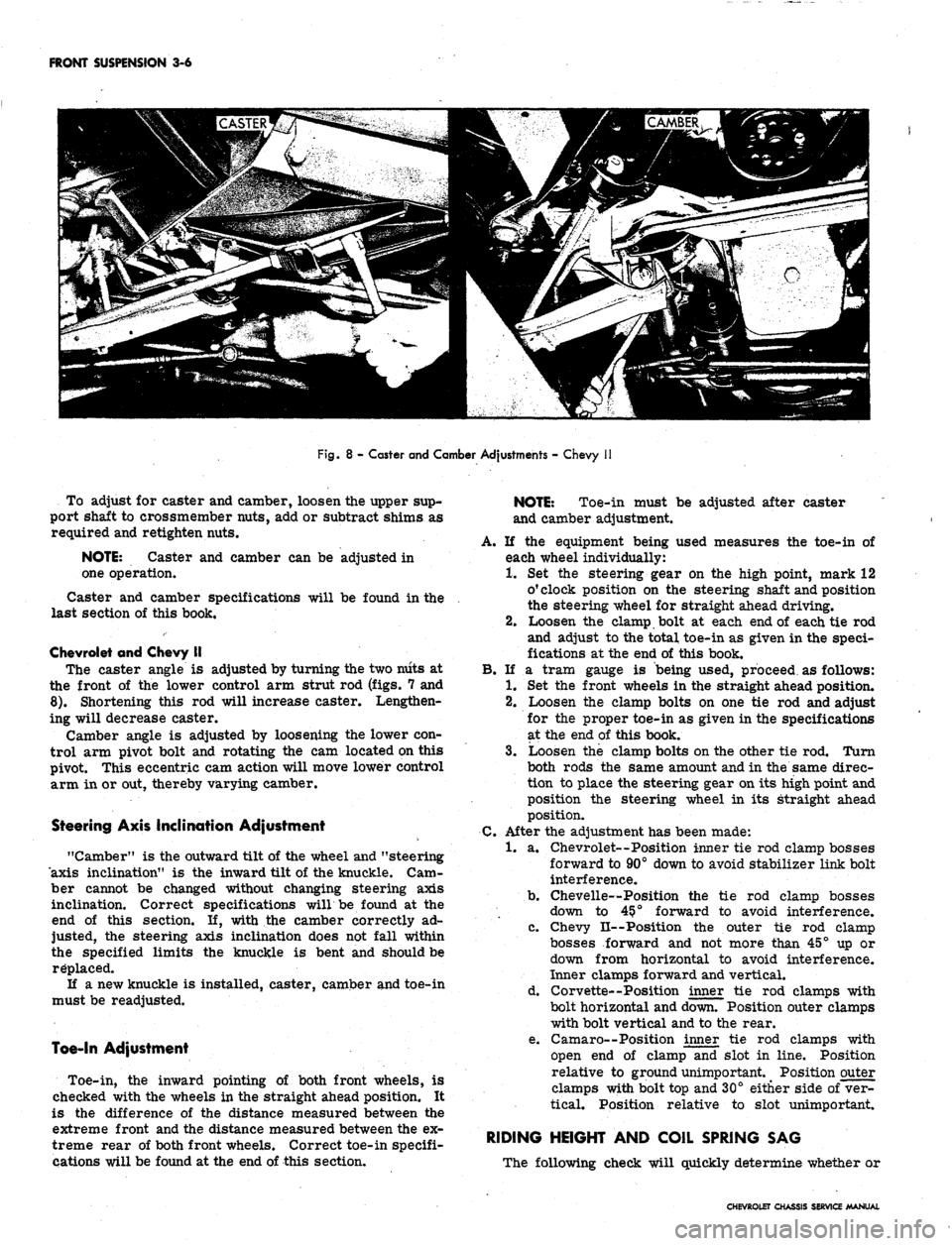
Fig.
8 - Caster and Camber Adjustments - Chevy
To adjust for caster and camber, loosen the upper sup-
port shaft to crossmember nuts, add or subtract shims as
required and retighten nuts.
NOTE:
Caster and camber can be adjusted in
one operation.
Caster and camber specifications will be found in the
last section of this book.
Chevrolet and Chevy II
The caster angle is adjusted by turning the two niits at
the front of the lower control arm strut rod (figs. 7 and
8).
Shortening this rod will increase caster. Lengthen-
ing will decrease caster.
Camber angle is adjusted by loosening the lower con-
trol arm pivot bolt and rotating the cam located on this
pivot. This eccentric cam action will move lower control
arm in or out, thereby varying camber.
Steering Axis Inclination Adjustment
"Camber" is the outward tilt of the wheel and "steering
axis inclination" is the inward tilt of the knuckle. Cam-
ber cannot be changed without changing steering axis
inclination. Correct specifications willbe found at the
end of this section. If, with the camber correctly ad-
justed, the steering axis inclination does not fall within
the specified limits the knuckle is bent and should be
replaced.
If a new knuckle is installed, caster, camber and toe-in
must be readjusted.
Toe-In Adjustment
Toe-in, the inward pointing of both front wheels, is
checked with the wheels in the straight ahead position. It
is the difference of the distance measured between the
extreme front and the distance measured between the ex-
treme rear of both front wheels. Correct toe-in specifi-
cations will be found at the end of this section.
NOTE:
Toe-in must be adjusted after caster
and camber adjustment.
A. If the equipment being used measures the toe-in of
each wheel individually:
1.
Set the steering gear on the high point, mark 12
o'clock position on the steering shaft and position
the steering wheel for straight ahead driving.
2.
Loosen the clamp bolt at each end of each tie rod
and adjust to the total toe-in as given in the speci-
fications at the end of this book.
B.
If a tram gauge is being used, proceed as follows:
1.
Set the front wheels in the straight ahead position.
2.
Loosen the clamp bolts on one tie rod and adjust
for the proper toe-in as given in the specifications
at the end of this book.
3.
Loosen the clamp bolts on the other tie rod. Turn
both rods the same amount and in the same direc-
tion to place the steering gear on its high point and
position the steering wheel in its straight ahead
position.
C.
After the adjustment has been made:
1.
a. Chevrolet—Position inner tie rod clamp bosses
forward to 90° down to avoid stabilizer link bolt
interference.
b.
Chevelle—Position the tie rod clamp bosses
down to 45?° forward to avoid interference.
c. Chevy II--Position the outer tie rod clamp
bosses forward and not more than 45° up or
down from horizontal to avoid interference.
Inner clamps forward and vertical.
d. Corvette--Position inner tie rod clamps with
bolt horizontal and down. Position outer clamps
with bolt vertical and to the rear.
e. Camaro—Position inner tie rod clamps with
open end of clamp and slot in line. Position
relative to ground unimportant. Position outer
clamps with bolt top and 30° either side of ver-
tical. Position relative to slot unimportant.
RIDING HEIGHT AND COIL SPRING SAG
The following check will quickly determine whether or
CHEVROLET CHASSIS SERVICE MANUAL
Page 196 of 659
REAR SUSPENSION AND DRIVE LINE 4-6
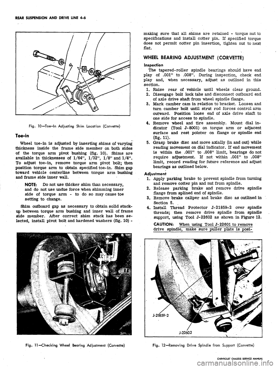
Fig.
10—Toe-in Adjusting Shim Location (Corvette)
Toe-in
Wheel toe-in is adjusted by inserting shims of varying
thickness inside the frame side member on both sides
of the torque arm pivot bushing (fig. 10). Shims are
available in thicknesses of
1/64",
1/32",
1/8" and 1/4".
To adjust toe-in, remove torque arm pivot bolt; then
position torque arm to obtain specified toe-in. Shim gap
toward vehicle centerline between torque arm bushing
and frame side inner wall.
NOTE: Do not use thicker shim than necessary,
and do not use undue force when shimming inner
side of torque arm - to do so may cause toe
setting to change.
Shim outboard gap as necessary to obtain solid stack-
up between torque arm bushing and inner wall of frame
side member. After correct shim stack has been se-
lected, install pivot bolt and hardened washers (fig. 10) -
making sure that all shims are retained - torque nut to
specifications and install cotter pin. If specified torque
does not permit cotter pin insertion, tighten nut to next
flat.
WHEEL BEARING ADJUSTMENT (CORVETTE)
inspection
The tapered-roller spindle bearings should have end
play of .001" to
.008".
During inspection, check end
play and, when necessary, adjust as outlined in this
section.
1.
Raise rear of vehicle until wheels clear ground.
2.
Disengage bolt lock tabs and disconnect outboard end
of axle drive shaft from wheel spindle flange.
3.
Mark camber cam in relation to bracket. Loosen and
turn camber bolt until strut rod forces control arm
outward. Position loose end of axle drive shaft to
one side for access to spindle.
4.
Remove wheel and tire assembly. Mount dial in-
dicator (Tool J-8001) on torque arm or adjacent
surface and rest pointer on flange or spindle end
(fig. H).
5.
Grasp brake disc and move axially (in and out) while
reading movement on dial indicator. If end movement
is within the .001" to .008" limit, bearings do not
require adjustment. If not within .001" to .008"
limit, record reading for future reference and adjust
bearings as outlined below.
Adjustment
1.
Apply parking brake to prevent spindle from turning
and remove cotter pin and nut from spindle.
2.
Release parking brake and remove drive spindle
flange from splined end of spindle.
3.
Remove brake caliper and brake disc as outlined in
Section 5.
4.
Install Thread Protector J-21859-2 over spindle
threads; then remove drive spindle from spindle
support, using Tool J-22602 as shown in Figure 12.
CAUTION: When using Tool J-22601 to remove
drive spindle, make sure puller plate is posi-
Fig.
11—Checking Wheel Bearing Adjustment (Corvette)
Fig. 12—Removing Drive Spindle from Support (Corvette)
CHEVROLET CHASSIS SERVICE MANUAL
Page 240 of 659
BRAKES 5-7
LATCH PLATE
DIE BLOCK
TUBE
UPSET FLARE PUNCH
RAM GUIDE
STOP PLATE
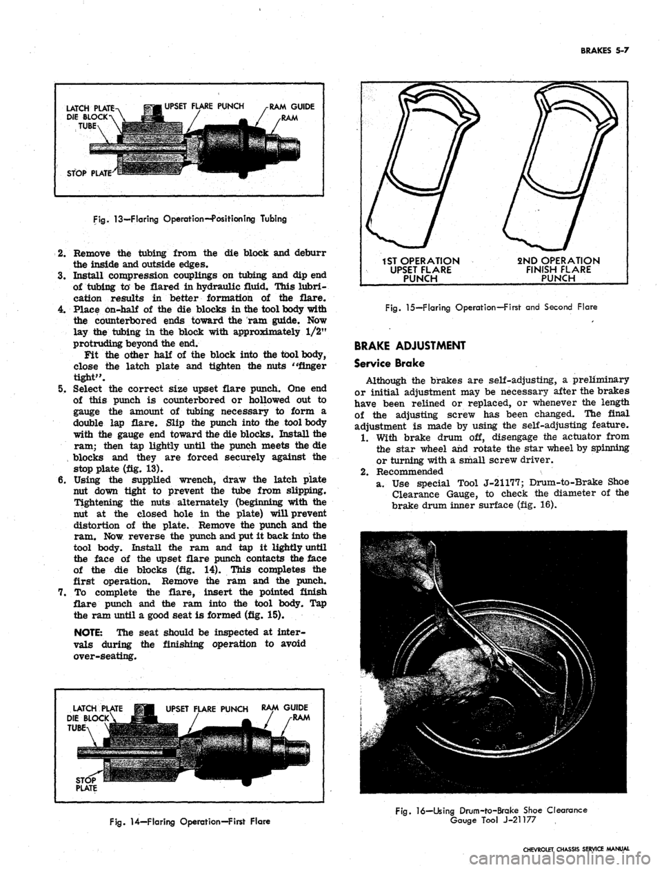
Fig.
13—Flaring Operation--Position ing Tubing
2.
Remove the tubing from the die block and deburr
the inside and outside edges.
3.
Install compression couplings on tubing and dip end
of tubing to be flared in hydraulic fluid. This lubri-
cation results in better formation of the flare.
4.
Place on-half of the die blocks in the tool body with
the counterbored ends toward the ram guide. Now
lay the tubing in the block with approximately 1/2"
protruding beyond the end.
Fit the other half of the block into the tool body,
close the latch plate and tighten the nuts "finger
tight".
5. Select the correct size upset flare punch. One end
of this punch is counterbored or hollowed out to
gauge the amount of tubing necessary to form a
double lap flare. Slip the punch into the tool body
with the gauge end toward the die blocks. Install the
ram; then tap lightly until the punch meets the die
, blocks and they are forced securely against the
stop plate (fig. 13).
6. Using the supplied wrench, draw the latch plate
nut down tight to prevent the tube from slipping.
Tightening the nuts alternately (beginning with the
nut at the closed hole in the plate) will prevent
distortion of the plate. Remove the punch and the
ram. Now reverse the punch and put it back into the
tool body. Install the ram and tap it lightly until
the face of the upset flare punch contacts the face
of the die blocks (fig. 14). This completes the
first operation. Remove the ram and the punch.
7. To complete the flare, insert the pointed finish
flare punch and the ram into the tool body. Tap
the ram until a good seat is formed (fig. 15).
NOTE:
The seat should be inspected at inter-
vals during the finishing operation to avoid
over-seating.
LATCH
DIE BLOCK
TUBE
UPSET FLARE PUNCH
RAM GUIDE
RAM
1ST OPERATION
UPSET FLARE
PUNCH
2ND OPERATION
FINISH FLARE
PUNCH
Fig.
15—Flaring Operation—First and Second Flare
BRAKE ADJUSTMENT
Service Brake
Although the brakes are self-adjusting, a preliminary
or initial adjustment may be necessary after the brakes
have been relined or replaced, or whenever the length
of the adjusting screw has been changed. The final
adjustment is made by using the self-adjusting feature.
1.
With brake drum off, disengage the actuator from
the star wheel and rotate the star wheel by spinning
or turning with a small screw driver.
2.
Recommended
a. Use special Tool J-21177; Drum-to-Brake Shoe
Clearance Gauge, to check the diameter of the
brake drum inner surface (fig. 16).
Fig.
14—Flaring Operation—First Flare
Fig.
16—Using Drum-to-Brake Shoe Clearance
Gauge Tool J-21177
CHEVROLET CHASSIS SERVICE MANUAL
Page 277 of 659
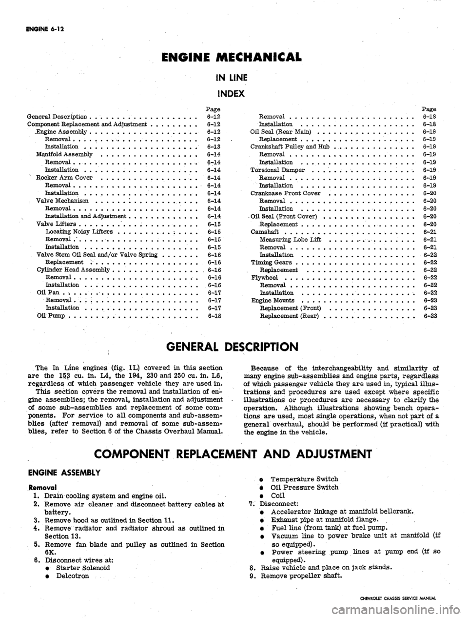
ENGINE
6-12
ENGINE
MECHANICAL
IN LINE
INDEX
Page
General Description . „ 6-12
Component Replacement and Adjustment 6-12
.Engine Assembly 6-12
Removal 6-12
Installation 6-13
Manifold Assembly 6-14
Removal . 6-14
Installation 6-14
Rocker Arm Cover . 6-14
Removal 6-14
mstallation . . . 6-14
Valve Mechanism
......
1 6-14
Removal 6-14
Installation and Adjustment . 6-14
Valve Lifters
..............
6-15
Locating Noisy Lifters
„.;....
6-15
Removal
.'.*...•
6-15
Installation . 6-15
Valve Stem Oil Seal and/or Valve Spring . 6-16
Replacement . 6-16
Cylinder Head Assembly . 6-16
Removal 6-16
Installation . 6-16
Oil Pan . » 6-17
Removal . . . ; . . 6-17
Installation
.........
. 6-17
Oil Pump . 6-18
Page
Removal . 6-18
Installation . 6-18
Oil Seal (Rear Main) . 6-19
Replacement 6-19
Crankshaft Pulley and Hub 6-19
Removal 6-19
Installation 6-19
Torsional Damper 6-19
Removal 6-19
Installation 6-19
Crankcase Front Cover . 6-20
Removal . 6-20
Installation 6-20
•
Oil Seal (Front Cover) 6-20
Replacement 6-20
Camshaft 6-21
Measuring Lobe Lift . ... .
.-.••.-.
6-21
Removal 6-21
Installation 6-22
Timing Gears
..••••.............••• 6—22
Replacement
6-22
Flywheel
6-22
Removal
* 6-22
Installation
6-22
Engine
Mounts
6-23
Replacement
(Front)
6-23
Replacement
(Rear)
. 6-23
GENERAL DESCRIPTION
The
In
Line engines
(fig. 1L)
covered
in
this section
are
the 1H3 cu. in. L4, the 194,
230
and
250
cu. in. L6,
regardless
of
which passenger vehicle they
are
used
in.
This section covers
the
removal
and
installation
of en-
gine assemblies;
the
removal, installation
and
adjustment
of some sub-assemblies
and
replacement
of
some
com-
ponents.
For
service
to all
components
and
sub-assem-
blies (after removal)
and
removal
of
some sub-assem-
blies,
refer
to
Section
6 of the
Chassis Overhaul Manual.
Because
of the
interchangeability
and
similarity
of
many engine sub-assemblies
and
engine parts, regardless
of which passenger vehicle they
are
used
in,
typical illus-
trations
and
procedures
are
used except where specific
illustrations
or
procedures
are
necessary
to
clarify
the
operation. Although illustrations showing bench opera-
tions
are
used, most single operations, when
not
part
of a
general overhaul, should
be
performed
(if
practical) with
the engine
in the
vehicle.
COMPONENT REPLACEMENT
AND
ADJUSTMENT
ENGINE ASSEMBLY
Removal
1.
Drain cooling system
and
engine
oil.
2.
Remove
air
cleaner
and
disconnect battery cables
at 7.
battery.
3.
Remove hood
as
outlined
in
Section 11.
4.
Remove radiator
and
radiator shroud
as
outlined
in
Section 13.
5.
Remove
fan
blade
and
pulley
as
outlined
in
Section
6K.
6. Disconnect wires
at:
• Starter Solenoid
8.
• Delcotron
9.
Temperature Switch
Oil Pressure Switch
Coil
Disconnect:
Accelerator linkage
at
manifold bellerank.
Exhaust pipe
at
manifold flange.
.
Fuel line (from tank)
at
fuel pump.
Vacuum line
to
power brake unit
at
manifold
(if
so equipped).
• Power steering pump lines
at
pump
end (if so
equipped).
Raise vehicle
and
place
on
jack stands.
Remove propeller shaft.
CHEVROLET CHASSIS SERVICE MANUAL
Page 290 of 659
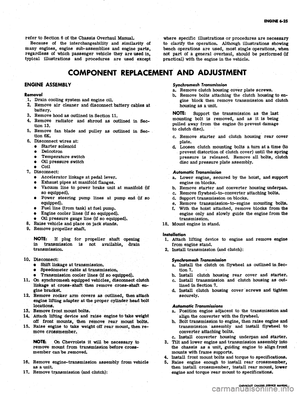
ENGINE 6-25
refer to Section 6 of the Chassis Overhaul Manual.
Because of the interchangeability and similarity of
many engines, engine sub-assemblies and engine parts,
regardless of which passenger vehicle they are used in,
typical illustrations and procedures are used except
where specific illustrations or procedures are necessary
to clarify the operation. Although illustrations showing
bench operations are used, most single operations, when
not part of a general overhaul, should be performed (if
practical) with the engine in the vehicle.
COMPONENT REPLACEMENT AND ADJUSTMENT
ENGINE ASSEMBLY
Removal
• .1. Drain cooling system and engine oil.
2.
Remove air cleaner and disconnect battery cables at
battery.
3.
Remove hood as outlined in Section 11.
4.
Remove radiator and shroud as outlined in Sec-
tion 13.
5. Remove fan blade and pulley as outlined in Sec-
tion 6K.
6. Disconnect wires at:
• Starter solenoid
• Delcotron
• Temperature switch
• Oil pressure switch
• Coil
7. Disconnect:
• Accelerator linkage at pedal lever.
• Exhaust pipes at manifold flanges.
• Vacuum line to power brake unit at manifold (if
so equipped),
• Power steering pump lines at pump end (if so
equipped).
• Fuel line (from tank) at fuel pump.
• Engine cooler lines (if so equipped).
• Oil pressure gauge line (if so equipped).
8. Raise vehicle and place on jack stands.
9. Remove propeller shaft.
NOTE:
If plug for propeller shaft opening
in transmission is not available, drain
transmission.
10.
Disconnect:
• Shift linkage at transmission.
• Speedometer cable at transmission.
• Transmission cooler lines (if so equipped).
11.
On synchromesh equipped vehicles, disconnect clutch
linkage at cross-shaft then remove cross-shaft en-
gine bracket.
12.
Remove rocker arm covers as outlined, then attach
engine lifting adapter at the proper cylinder head bolt
locations.
13.
Remove front mount bolts.
14.
Attach lifting device and raise engine to take weight
off front mounts, then remove rear mount bolts.
15.
Raise engine to take weight off rear mount, then re-
move crossmember.
NOTE:
On Chevrolets it will be necessary to
remove mount from transmission before cross-
member can be removed.
16.
Remove engine-transmission assembly from vehicle
as a unit.
17.
Remove transmission (and clutch):
Synchromesh Transmission
a. Remove clutch housing cover plate screws.
b.
Remove bolts attaching the clutch housing to en-
gine block then remove transmission and clutch
housing as a unit.
NOTE:
Support the transmission as the last
mounting bolt is removed, and as it is being
pulled away from the engine (to prevent damage
to clutch disc).
c. Remove starter and clutch housing rear cover
plate.
d. Loosen clutch mounting bolts a turn at a time (to
prevent distortion of clutch cover) until the spring
pressure is released. Remove all bolts, clutch
disc and pressure plate assembly.
Automatic
Transmission
a. Lower engine, secured by the hoist, and support
engine on blocks.
b.
Remove starter and converter housing underpan.
c. Remove flywheel-to-converter attaching bolts.
d. Support transmission on blocks.
e. Remove transmission-to-engine mounting bolts.
f. With the hoist attached, remove blocks from the
engine only and slowly guide the engine from the
transmission.
18.
Mount engine in stand.
Installation
1.
Attach lifting device to engine and remove engine
from engine stand.
2.
Install transmission (and clutch):
Synchromesh Transmission
a. Install the clutch on flywheel as outlined in Sec-
tion 7.
b.
Install clutch housing rear cover and starter.
c. Install transmission and clutch housing as out-
lined in Section 7.
d. Install clutch housing cover screws and tighten
securely.
Automatic
Transmissions
a. Position engine adjacent to the transmission and
align the converter with the flywheel.
b.
Bolt transmission to engine, then raise engine and
transmission assembly and install flywheel to
converter attaching bolts.
c. Install converter housing underpan and starter.
3.
Tilt and lower engine and transmission assembly into
the chassis as a unit, guiding engine to align front
mounts with frame supports.
4.
Install front mount bolts and torque to specifications.
5. Raise engine enough to install rear crossmember,
then install crossmember, install rear mount, lower
engine and torque rear mount to specifications.
CHEVROLET CHASSIS SERVICE MANUAL