roof rack CHRYSLER VOYAGER 2001 Service Manual
[x] Cancel search | Manufacturer: CHRYSLER, Model Year: 2001, Model line: VOYAGER, Model: CHRYSLER VOYAGER 2001Pages: 4284, PDF Size: 83.53 MB
Page 1818 of 4284
ANTENNA MODULE
DESCRIPTION
The antenna module is an electromagnetic circuit
component designed to capture and enhance RF
(Radio Frequency) signals in both the AM and FM
broadcast bands. The antenna module is mounted to
the right rear roof rail under the headliner. The mod-
ule is grounded through the mounting bracket and
fastener. The module has a two wire electrical con-
nector that connects to the integral radio antenna,located on the right rear quarter glass. There is also
an electrical connector for battery voltage and a coax
cable connector.OPERATION
The antenna module receives both AM and FM
radio signals supplied by the side window integral
radio antenna system and selectively amplifies them.
The amplified signal is then sent through the body
length coax cable to the radio input.
DIAGNOSIS AND TESTING - ANTENNA MODULE
CONDITION POSSIBLE CAUSES CORRECTION
NO AM RECEPTION,
WEAK FM RECEPTION1. Antenna module to antenna
connector open or disconnected.1. Repair open, reconnect
antenna module connector to
glass mounted antenna.
2. Coax open or disconnected. 2. Repair open, reconnect coax.
3. No battery power at antenna
module.3. Check fuse. if okay, repair
open in battery voltage circuit.
NO AM OR FM
RECEPTION1. Coax disconnected at radio. 1. Reconnect coax.
2. Coax shorted to ground. 2. Repair or Replace coax
WEAK OR NO AM/FM
RECEPTION1. Antenna Module faulty. 1. Substitute known good
module. If reception improves,
Antenna Module was faulty.
REMOVAL
(1) Disconnect and isolate the battery negative
cable.
(2) Lower headliner as necessary to access
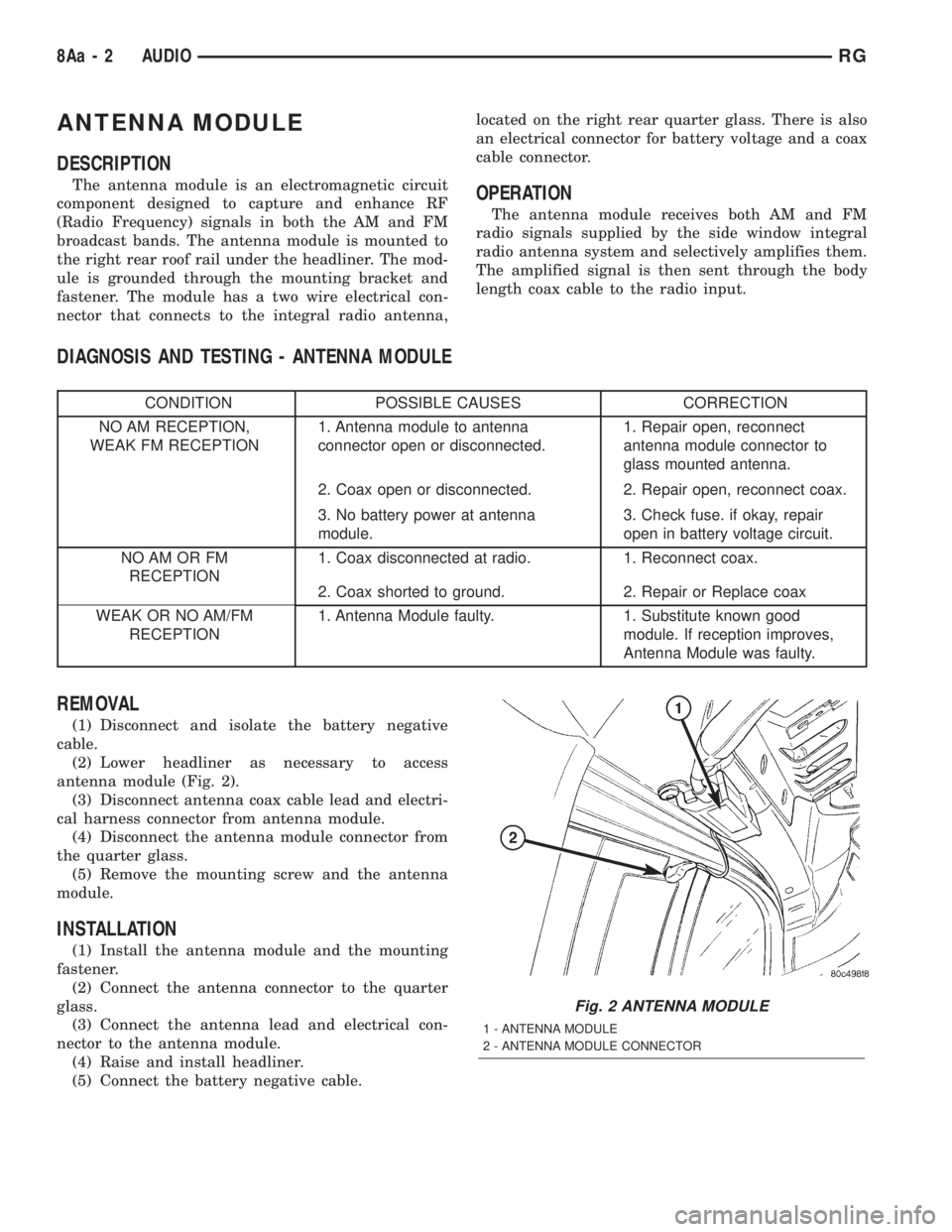
antenna module (Fig. 2).
(3) Disconnect antenna coax cable lead and electri-
cal harness connector from antenna module.
(4) Disconnect the antenna module connector from
the quarter glass.
(5) Remove the mounting screw and the antenna
module.
INSTALLATION
(1) Install the antenna module and the mounting
fastener.
(2) Connect the antenna connector to the quarter
glass.
(3) Connect the antenna lead and electrical con-
nector to the antenna module.
(4) Raise and install headliner.
(5) Connect the battery negative cable.
Fig. 2 ANTENNA MODULE
1 - ANTENNA MODULE
2 - ANTENNA MODULE CONNECTOR
8Aa - 2 AUDIORG
Page 1970 of 4284
OVERHEAD CONSOLE
TABLE OF CONTENTS
page page
OVERHEAD CONSOLE
DESCRIPTION............................2
OPERATION.............................3
DIAGNOSIS AND TESTING..................3
DIAGNOSIS & TESTING...................3
STANDARD PROCEDURE...................4
COURTESY LAMP REPLACEMENT..........4
COMPASS CALIBRATION..................4
COMPASS DEMAGNETIZING...............4
COMPASS VARIATION ADJUSTMENT........5
REMOVAL...............................6
INSTALLATION............................6
ELECTRONIC VEHICLE INFO CENTER
DESCRIPTION............................6
OPERATION.............................7
DIAGNOSIS AND TESTING..................7
TRAVELER MESSAGES...................7
STANDARD PROCEDURE...................8
EVIC PROGRAMMING....................8
REMOVAL...............................9
INSTALLATION............................9COMPASS/MINI-TRIP COMPUTER
DESCRIPTION............................9
OPERATION.............................10
DIAGNOSIS AND TESTING.................10
DIAGNOSIS AND TESTING...............10
REMOVAL..............................10
INSTALLATION...........................10
UNIVERSAL TRANSMITTER
DESCRIPTION...........................10
OPERATION.............................10
DIAGNOSIS AND TESTING.................11
UNIVERSAL GARAGE DOOR OPENER......11
AMBIENT TEMP SENSOR
DESCRIPTION...........................11
OPERATION.............................11
DIAGNOSIS AND TESTING.................11
AMBIENT TEMPERATURE SENSOR.........11
AMBIENT TEMPERATURE SENSOR
CIRCUIT..............................11
REMOVAL..............................12
INSTALLATION...........................12
OVERHEAD CONSOLE
DESCRIPTION
The available overhead consoles on RS models can
include the Electronic Vehicle Information Center
(EVIC), Compass Mini-Trip Computer (CMTC) or a
Compass Temperature Computer (CT). All consoles
are equipped with two reading/courtesy lamps and if
the vehicle is equipped with a power liftgate or
power sliding door(s) the overhead console will also
include command switches for these features. The
overhead console is mounted with one screw and two
snap clips to a molded plastic retainer bracket
located above the headliner.
DESCRIPTION - COMPASS
All the available overhead consoles on this model
include Compass information. While in the compass/
thermometer mode, the compass will display the
direction in which the vehicle is pointed using the
eight major compass headings (Examples: north is N,
northeast is NE). The self-calibrating compass unit
requires no adjusting in normal use. The only cali-
bration that may prove necessary is to drive the vehi-
cle in three complete circles at 5 to 8 kilometers-per-
hour (3 to 5 miles-per-hour), on level ground, in notless than forty-eight seconds. This will reorient the
compass unit to its vehicle.
The compass unit also will compensate for magne-
tism the body of the vehicle may acquire during nor-
mal use. However, avoid placing anything magnetic
directly on the roof of the vehicle. Magnetic mounts
for an antenna, a repair order hat, or a funeral pro-
cession flag can exceed the compensating ability of
the compass unit if placed on the roof panel. Mag-
netic bit drivers used on the fasteners that hold the
overhead console assembly to the roof header can
also affect compass operation. If the vehicle roof
should become magnetized, the demagnetizing and
calibration procedures found in this section may be
required to restore proper compass operation.DESCRIPTION - THERMOMETER
All the available overhead consoles on this model
include Temperature information. The thermometer
displays the outside ambient temperature in whole
degrees. The temperature display can be toggled
from Fahrenheit to Celsius by selecting the desired
U.S./Metric option from the customer programmable
features. The displayed temperature is not an instant
reading of conditions, but an average temperature. It
may take the thermometer display several minutes
to respond to a major temperature change, such as
8M - 2 OVERHEAD CONSOLERS
Page 3399 of 4284
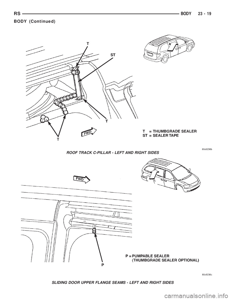
ROOF TRACK C-PILLAR - LEFT AND RIGHT SIDES
SLIDING DOOR UPPER FLANGE SEAMS - LEFT AND RIGHT SIDES
RSBODY23-19
BODY (Continued)
Page 3426 of 4284
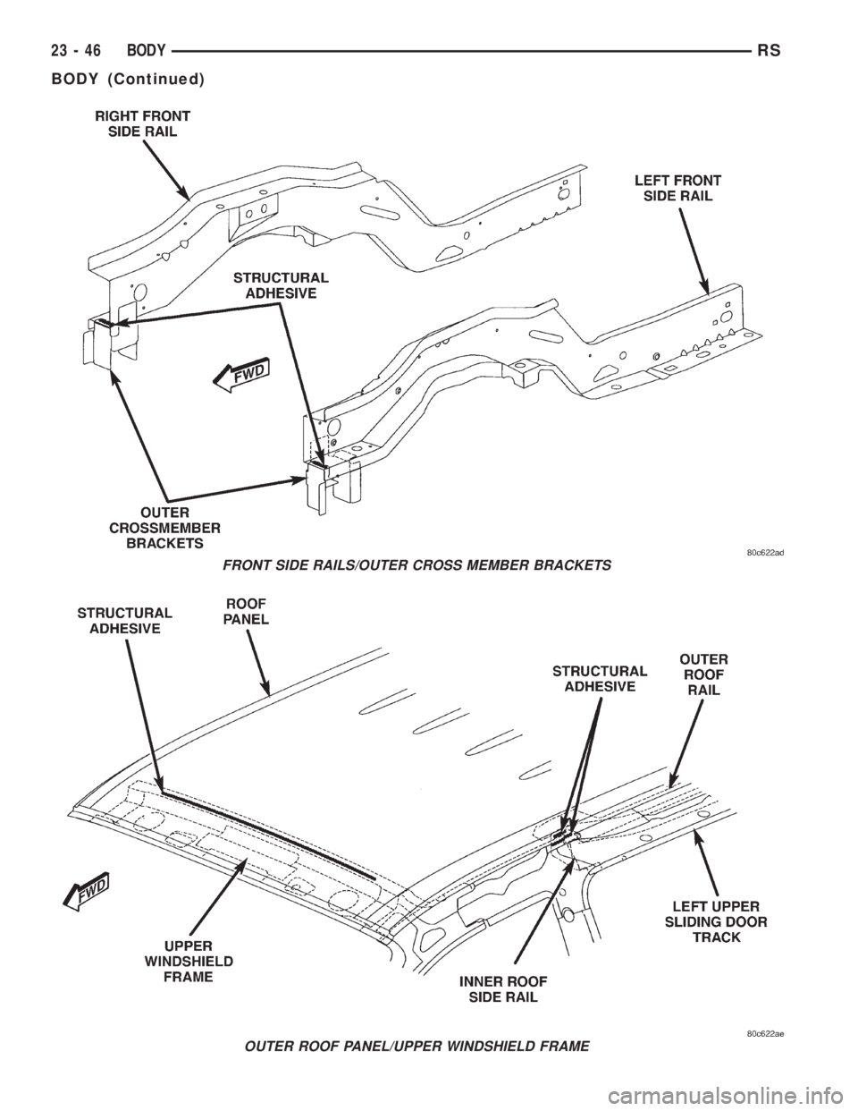
FRONT SIDE RAILS/OUTER CROSS MEMBER BRACKETS
OUTER ROOF PANEL/UPPER WINDSHIELD FRAME
23 - 46 BODYRS
BODY (Continued)
Page 3529 of 4284
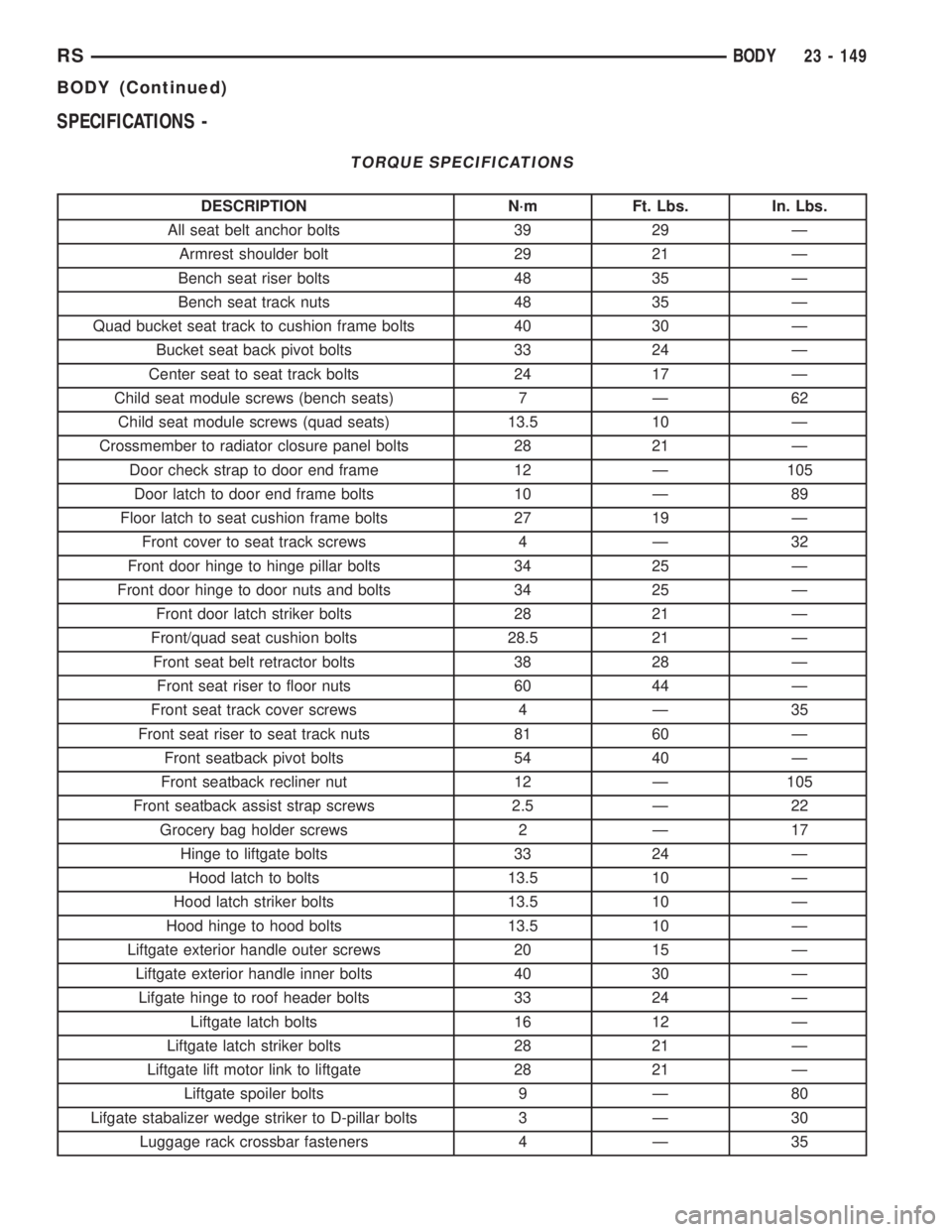
SPECIFICATIONS -
TORQUE SPECIFICATIONS
DESCRIPTION N´m Ft. Lbs. In. Lbs.
All seat belt anchor bolts 39 29 Ð
Armrest shoulder bolt 29 21 Ð
Bench seat riser bolts 48 35 Ð
Bench seat track nuts 48 35 Ð
Quad bucket seat track to cushion frame bolts 40 30 Ð
Bucket seat back pivot bolts 33 24 Ð
Center seat to seat track bolts 24 17 Ð
Child seat module screws (bench seats) 7 Ð 62
Child seat module screws (quad seats) 13.5 10 Ð
Crossmember to radiator closure panel bolts 28 21 Ð
Door check strap to door end frame 12 Ð 105
Door latch to door end frame bolts 10 Ð 89
Floor latch to seat cushion frame bolts 27 19 Ð
Front cover to seat track screws 4 Ð 32
Front door hinge to hinge pillar bolts 34 25 Ð
Front door hinge to door nuts and bolts 34 25 Ð
Front door latch striker bolts 28 21 Ð
Front/quad seat cushion bolts 28.5 21 Ð
Front seat belt retractor bolts 38 28 Ð
Front seat riser to floor nuts 60 44 Ð
Front seat track cover screws 4 Ð 35
Front seat riser to seat track nuts 81 60 Ð
Front seatback pivot bolts 54 40 Ð
Front seatback recliner nut 12 Ð 105
Front seatback assist strap screws 2.5 Ð 22
Grocery bag holder screws 2 Ð 17
Hinge to liftgate bolts 33 24 Ð
Hood latch to bolts 13.5 10 Ð
Hood latch striker bolts 13.5 10 Ð
Hood hinge to hood bolts 13.5 10 Ð
Liftgate exterior handle outer screws 20 15 Ð
Liftgate exterior handle inner bolts 40 30 Ð
Lifgate hinge to roof header bolts 33 24 Ð
Liftgate latch bolts 16 12 Ð
Liftgate latch striker bolts 28 21 Ð
Liftgate lift motor link to liftgate 28 21 Ð
Liftgate spoiler bolts 9 Ð 80
Lifgate stabalizer wedge striker to D-pillar bolts 3 Ð 30
Luggage rack crossbar fasteners 4 Ð 35
RSBODY23 - 149
BODY (Continued)
Page 3557 of 4284
(5) Engage rigging cam to latch/lock control mech-
anism.
(6) Move clip on latch/lock control to bottom of slot
and engage linkage to latch/lock control.
(7) Verify sliding door operation. Adjust as neces-
sary.
(8) Install latch/lock cover.
(9) Place the watershield into position and press
securely to adhesive making sure to properly route
wiring and linkages.
(10) Install sliding door stop bumper. (Refer to 23 -
BODY/DOORS - SLIDING/STOP BUMPER -
INSTALLATION)
(11) Install sliding door trim panel. (Refer to 23 -
BODY/DOORS - SLIDING/TRIM PANEL - INSTAL-
LATION)
UPPER ROLLER
REMOVAL
(1) Open sliding door, do not latch open.
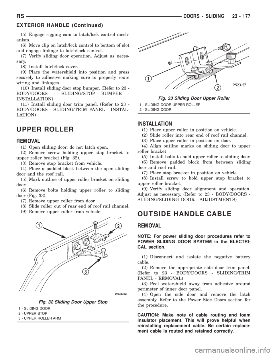
(2) Remove screw holding upper stop bracket to
upper roller bracket (Fig. 32).
(3) Remove stop bracket from vehicle.
(4) Place a padded block between the open sliding
door and the roof rail.
(5) Mark outline of upper roller bracket on sliding
door.
(6) Remove bolts holding upper roller to sliding
door (Fig. 33).
(7) Remove upper roller from door.
(8) Slide roller out of rear end of roof rail channel.
(9) Remove upper roller from vehicle.
INSTALLATION
(1) Place upper roller in position on vehicle.
(2) Slide roller into rear end of roof rail channel.
(3) Place upper roller in position on door.
(4) Align outline marks on sliding door to upper
roller bracket
(5) Install bolts to hold upper roller to sliding door.
(6) Remove padded block from between sliding
door and roof rail.
(7) Place stop bracket in position on vehicle.
(8) Install screw to hold upper stop bracket to
upper roller bracket.
(9) Verify sliding door alignment and operation.
Adjust as necessary. (Refer to 23 - BODY/DOORS -
SLIDING/SLIDING DOOR - ADJUSTMENTS)
OUTSIDE HANDLE CABLE
REMOVAL
NOTE: For power sliding door procedures refer to
POWER SLIDING DOOR SYSTEM in the ELECTRI-
CAL section.
(1) Disconnect and isolate the negative battery
cable.
(2) Remove the appropriate side door trim panel.
(Refer to 23 - BODY/DOORS - SLIDING/TRIM
PANEL - REMOVAL)
(3) Peel watershield away from adhesive around
perimeter of inner door panel.
(4) Open the side door and remove the latch
assembly. Refer to the Power Side Doors section for
the procedure.
CAUTION: Make note of cable routing and foam
insulator placement. This will prove helpful when
reinstalling replacement cable. Be certain replace-
ment cable is routed and retained correctly.
Fig. 32 Sliding Door Upper Stop
1 - SLIDING DOOR
2 - UPPER STOP
3 - UPPER ROLLER ARM
Fig. 33 Sliding Door Upper Roller
1 - SLIDING DOOR UPPER ROLLER
2 - SLIDING DOOR
RSDOORS - SLIDING23 - 177
EXTERIOR HANDLE (Continued)
Page 3564 of 4284
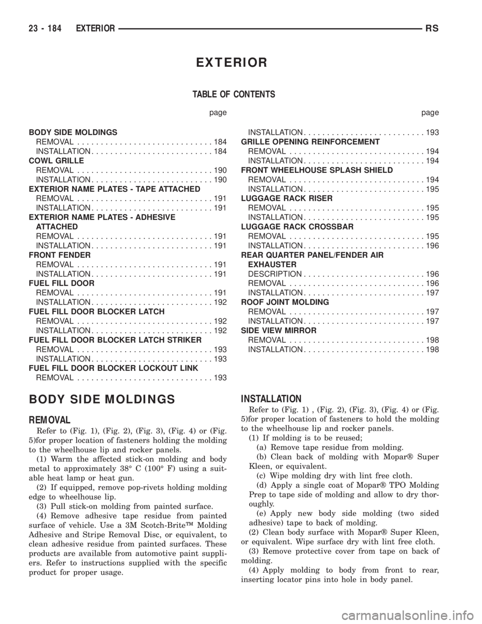
EXTERIOR
TABLE OF CONTENTS
page page
BODY SIDE MOLDINGS
REMOVAL.............................184
INSTALLATION..........................184
COWL GRILLE
REMOVAL.............................190
INSTALLATION..........................190
EXTERIOR NAME PLATES - TAPE ATTACHED
REMOVAL.............................191
INSTALLATION..........................191
EXTERIOR NAME PLATES - ADHESIVE
ATTACHED
REMOVAL.............................191
INSTALLATION..........................191
FRONT FENDER
REMOVAL.............................191
INSTALLATION..........................191
FUEL FILL DOOR
REMOVAL.............................191
INSTALLATION..........................192
FUEL FILL DOOR BLOCKER LATCH
REMOVAL.............................192
INSTALLATION..........................192
FUEL FILL DOOR BLOCKER LATCH STRIKER
REMOVAL.............................193
INSTALLATION..........................193
FUEL FILL DOOR BLOCKER LOCKOUT LINK
REMOVAL.............................193INSTALLATION..........................193
GRILLE OPENING REINFORCEMENT
REMOVAL.............................194
INSTALLATION..........................194
FRONT WHEELHOUSE SPLASH SHIELD
REMOVAL.............................194
INSTALLATION..........................195
LUGGAGE RACK RISER
REMOVAL.............................195
INSTALLATION..........................195
LUGGAGE RACK CROSSBAR
REMOVAL.............................195
INSTALLATION..........................196
REAR QUARTER PANEL/FENDER AIR
EXHAUSTER
DESCRIPTION..........................196
REMOVAL.............................196
INSTALLATION..........................197
ROOF JOINT MOLDING
REMOVAL.............................197
INSTALLATION..........................197
SIDE VIEW MIRROR
REMOVAL.............................198
INSTALLATION..........................198
BODY SIDE MOLDINGS
REMOVAL
Refer to (Fig. 1), (Fig. 2), (Fig. 3), (Fig. 4) or (Fig.
5)for proper location of fasteners holding the molding
to the wheelhouse lip and rocker panels.
(1) Warm the affected stick-on molding and body
metal to approximately 38É C (100É F) using a suit-
able heat lamp or heat gun.
(2) If equipped, remove pop-rivets holding molding
edge to wheelhouse lip.
(3) Pull stick-on molding from painted surface.
(4) Remove adhesive tape residue from painted
surface of vehicle. Use a 3M Scotch-BriteŸ Molding
Adhesive and Stripe Removal Disc, or equivalent, to
clean adhesive residue from painted surfaces. These
products are available from automotive paint suppli-
ers. Refer to instructions supplied with the specific
product for proper usage.
INSTALLATION
Refer to (Fig. 1) , (Fig. 2), (Fig. 3), (Fig. 4) or (Fig.
5)for proper location of fasteners to hold the molding
to the wheelhouse lip and rocker panels.
(1) If molding is to be reused;
(a) Remove tape residue from molding.
(b) Clean back of molding with Moparž Super
Kleen, or equivalent.
(c) Wipe molding dry with lint free cloth.
(d) Apply a single coat of Moparž TPO Molding
Prep to tape side of molding and allow to dry thor-
oughly.
(e) Apply new body side molding (two sided
adhesive) tape to back of molding.
(2) Clean body surface with Moparž Super Kleen,
or equivalent. Wipe surface dry with lint free cloth.
(3) Remove protective cover from tape on back of
molding.
(4) Apply molding to body from front to rear,
inserting locator pins into hole in body panel.
23 - 184 EXTERIORRS
Page 3599 of 4284
SUN VISOR SUPPORT
REMOVAL
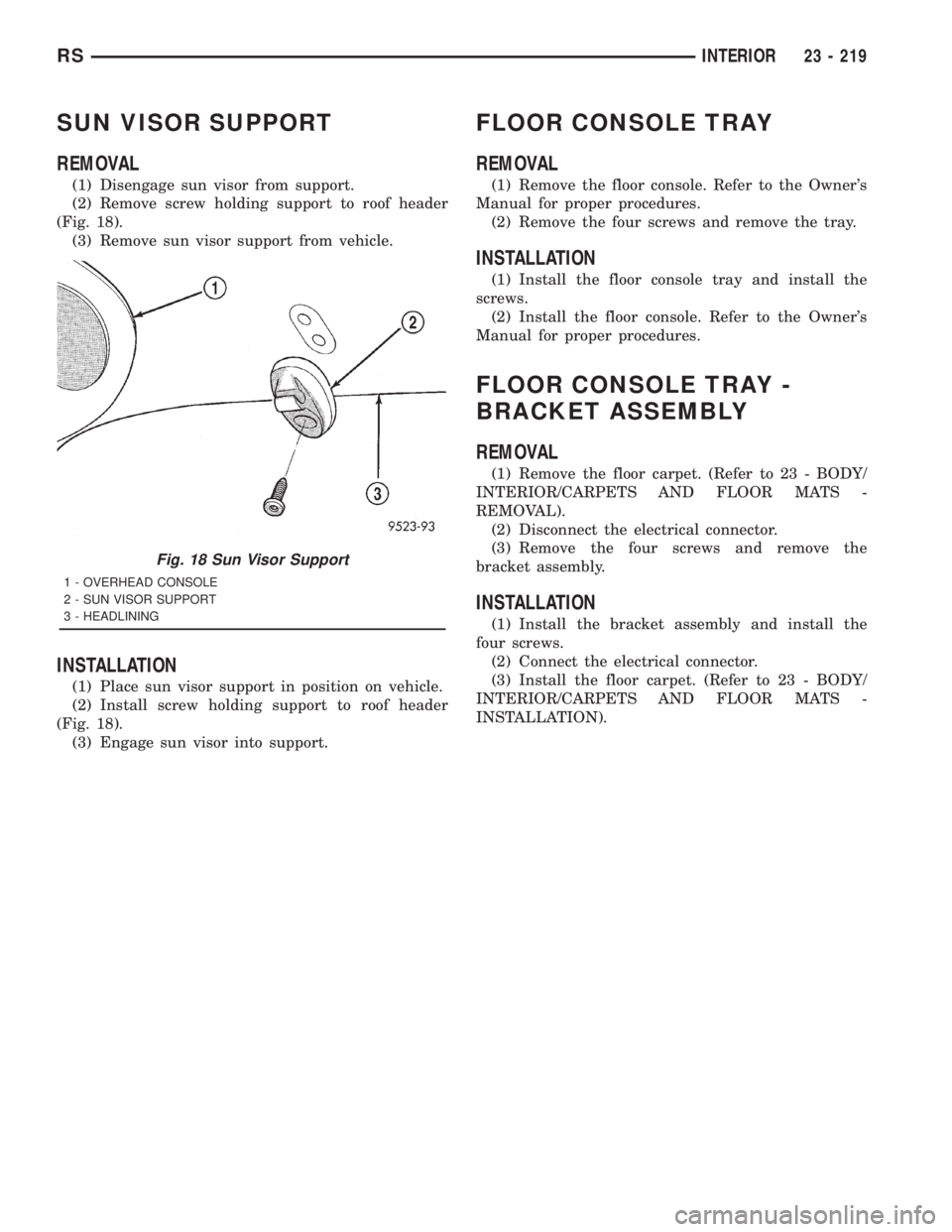
(1) Disengage sun visor from support.
(2) Remove screw holding support to roof header
(Fig. 18).
(3) Remove sun visor support from vehicle.
INSTALLATION
(1) Place sun visor support in position on vehicle.
(2) Install screw holding support to roof header
(Fig. 18).
(3) Engage sun visor into support.
FLOOR CONSOLE TRAY
REMOVAL
(1) Remove the floor console. Refer to the Owner's
Manual for proper procedures.
(2) Remove the four screws and remove the tray.
INSTALLATION
(1) Install the floor console tray and install the
screws.
(2) Install the floor console. Refer to the Owner's
Manual for proper procedures.
FLOOR CONSOLE TRAY -
BRACKET ASSEMBLY
REMOVAL
(1) Remove the floor carpet. (Refer to 23 - BODY/
INTERIOR/CARPETS AND FLOOR MATS -
REMOVAL).
(2) Disconnect the electrical connector.
(3) Remove the four screws and remove the
bracket assembly.
INSTALLATION
(1) Install the bracket assembly and install the
four screws.
(2) Connect the electrical connector.
(3) Install the floor carpet. (Refer to 23 - BODY/
INTERIOR/CARPETS AND FLOOR MATS -
INSTALLATION).
Fig. 18 Sun Visor Support
1 - OVERHEAD CONSOLE
2 - SUN VISOR SUPPORT
3 - HEADLINING
RSINTERIOR23 - 219
Page 3689 of 4284
(2) Drain the engine cooling system. (Refer to 7 -
COOLING - STANDARD PROCEDURE - COOLING
SYSTEM DRAIN).
(3) Disconnect and isolate the battery negative
cable.
(4) Raise and support the vehicle.
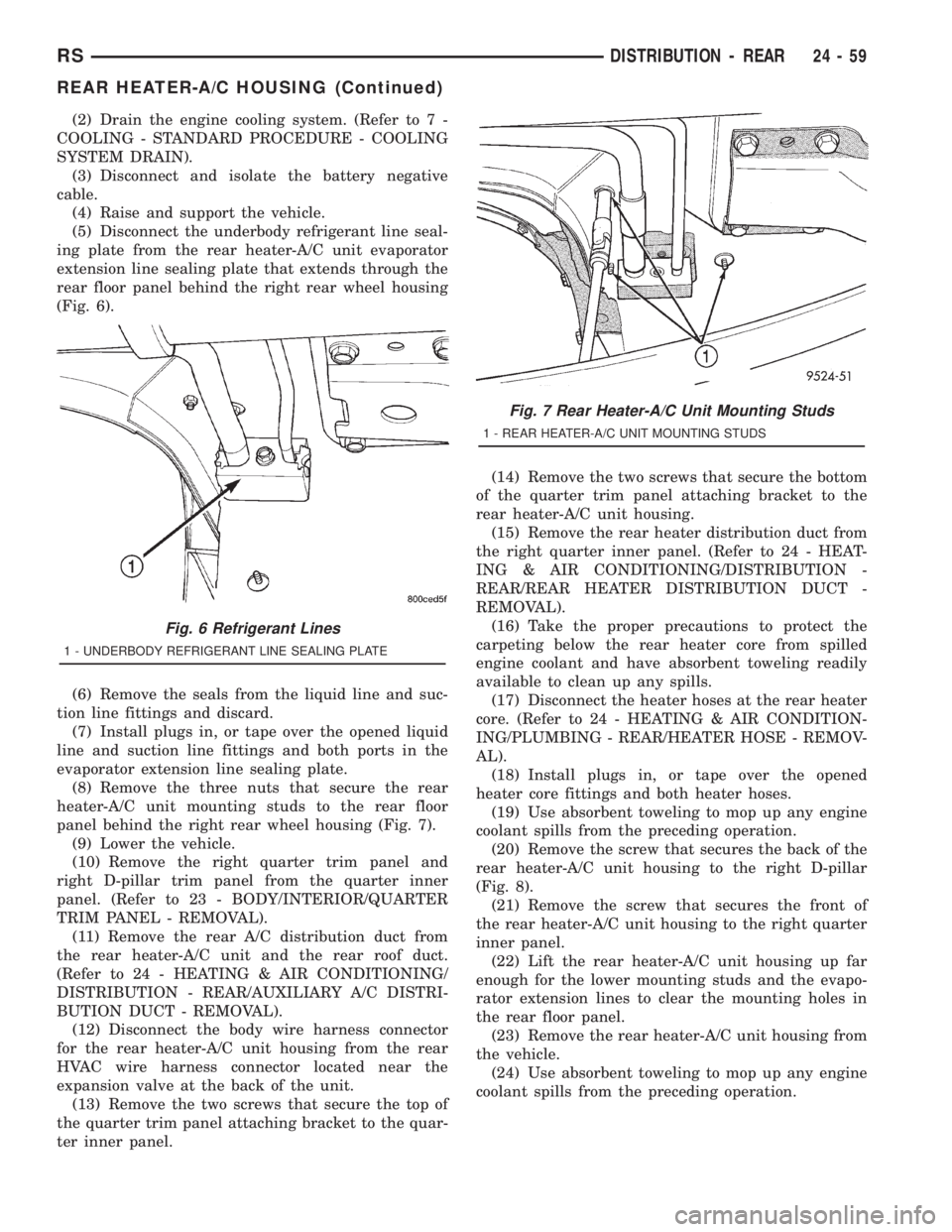
(5) Disconnect the underbody refrigerant line seal-
ing plate from the rear heater-A/C unit evaporator
extension line sealing plate that extends through the
rear floor panel behind the right rear wheel housing
(Fig. 6).
(6) Remove the seals from the liquid line and suc-
tion line fittings and discard.
(7) Install plugs in, or tape over the opened liquid
line and suction line fittings and both ports in the
evaporator extension line sealing plate.
(8) Remove the three nuts that secure the rear
heater-A/C unit mounting studs to the rear floor
panel behind the right rear wheel housing (Fig. 7).
(9) Lower the vehicle.
(10) Remove the right quarter trim panel and
right D-pillar trim panel from the quarter inner
panel. (Refer to 23 - BODY/INTERIOR/QUARTER
TRIM PANEL - REMOVAL).
(11) Remove the rear A/C distribution duct from
the rear heater-A/C unit and the rear roof duct.
(Refer to 24 - HEATING & AIR CONDITIONING/
DISTRIBUTION - REAR/AUXILIARY A/C DISTRI-
BUTION DUCT - REMOVAL).
(12) Disconnect the body wire harness connector
for the rear heater-A/C unit housing from the rear
HVAC wire harness connector located near the
expansion valve at the back of the unit.
(13) Remove the two screws that secure the top of
the quarter trim panel attaching bracket to the quar-
ter inner panel.(14) Remove the two screws that secure the bottom
of the quarter trim panel attaching bracket to the
rear heater-A/C unit housing.
(15) Remove the rear heater distribution duct from
the right quarter inner panel. (Refer to 24 - HEAT-
ING & AIR CONDITIONING/DISTRIBUTION -
REAR/REAR HEATER DISTRIBUTION DUCT -
REMOVAL).
(16) Take the proper precautions to protect the
carpeting below the rear heater core from spilled
engine coolant and have absorbent toweling readily
available to clean up any spills.
(17) Disconnect the heater hoses at the rear heater
core. (Refer to 24 - HEATING & AIR CONDITION-
ING/PLUMBING - REAR/HEATER HOSE - REMOV-
AL).
(18) Install plugs in, or tape over the opened
heater core fittings and both heater hoses.
(19) Use absorbent toweling to mop up any engine
coolant spills from the preceding operation.
(20) Remove the screw that secures the back of the
rear heater-A/C unit housing to the right D-pillar
(Fig. 8).
(21) Remove the screw that secures the front of
the rear heater-A/C unit housing to the right quarter
inner panel.
(22) Lift the rear heater-A/C unit housing up far
enough for the lower mounting studs and the evapo-
rator extension lines to clear the mounting holes in
the rear floor panel.
(23) Remove the rear heater-A/C unit housing from
the vehicle.
(24) Use absorbent toweling to mop up any engine
coolant spills from the preceding operation.
Fig. 6 Refrigerant Lines
1 - UNDERBODY REFRIGERANT LINE SEALING PLATE
Fig. 7 Rear Heater-A/C Unit Mounting Studs
1 - REAR HEATER-A/C UNIT MOUNTING STUDS
RSDISTRIBUTION - REAR24-59
REAR HEATER-A/C HOUSING (Continued)
Page 3691 of 4284
(8) Install and tighten the two screws that secure
the bottom of the quarter trim panel attaching
bracket to the rear heater-A/C unit housing. Tighten
the screws to 1.7 N´m (15 in. lbs.).
(9) Install and tighten the two screws that secure
the top of the quarter trim panel attaching bracket to
the quarter inner panel.
(10) Reconnect the body wire harness connector for
the rear heater-A/C unit housing to the rear HVAC
wire harness connector located near the expansion
valve at the back of the unit.
(11) Reinstall the auxiliary A/C distribution duct
onto the rear heater-A/C unit and the rear roof duct.
(Refer to 24 - HEATING & AIR CONDITIONING/
DISTRIBUTION - REAR/AUXILIARY A/C DISTRI-
BUTION DUCT - INSTALLATION).
(12) Reinstall the right quarter trim panel and
right D-pillar trim panel onto the quarter inner
panel. (Refer to 23 - BODY/INTERIOR/QUARTER
TRIM PANEL - INSTALLATION).
(13) Raise and support the vehicle.
(14) Install and tighten the three nuts that secure
the rear heater-A/C unit mounting studs to the rear
floor panel behind the right rear wheel housing (Fig.
7). Tighten the nuts to 9 N´m (80 in. lbs.).
(15) Remove the tape or plugs from the underbody
liquid line and suction line fittings and both ports in
the rear heater-A/C unit evaporator extension line
sealing plate that extends through the rear floor
panel behind the right rear wheel housing.
(16) Lubricate new rubber O-ring seals with clean
refrigerant oil and install them on the liquid line and
suction line fittings.
(17) Reconnect the underbody refrigerant line seal-
ing plate to the evaporator extension line sealing
plate (Fig. 6).
(18) Install and tighten the screw that secures the
underbody refrigerant line sealing plate to the evap-
orator extension line sealing plate. Tighten the screw
to 23 N´m (17 ft. lbs.).
(19) Lower the vehicle.
(20) Reconnect the battery negative cable.
(21) Refill the engine cooling system. (Refer to 7 -
COOLING - STANDARD PROCEDURE - COOLING
SYSTEM REFILL).
(22) Evacuate the refrigerant system. (Refer to 24
- HEATING & AIR CONDITIONING/PLUMBING -
FRONT/REFRIGERANT - STANDARD PROCE-
DURE - REFRIGERANT SYSTEM EVACUATE).
(23) Charge the refrigerant system. (Refer to 24 -
HEATING & AIR CONDITIONING/PLUMBING -
FRONT/REFRIGERANT - STANDARD PROCE-
DURE - REFRIGERANT SYSTEM CHARGE).REAR HEATER DISTRIBUTION
DUCT
REMOVAL
(1) Remove the trim from the right quarter inner
panel. (Refer to 23 - BODY/INTERIOR/RIGHT
QUARTER TRIM PANEL - REMOVAL).
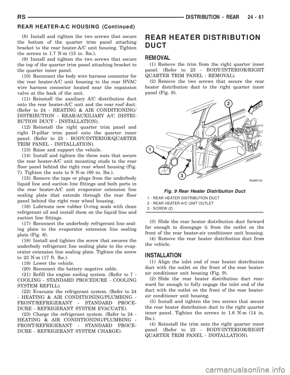
(2) Remove the two screws that secure the rear
heater distribution duct to the right quarter inner
panel (Fig. 9).
(3) Slide the rear heater distribution duct forward
far enough to disengage it from the outlet on the
front of the rear heater-air conditioner unit housing.
(4) Remove the rear heater distribution duct from
the vehicle.
INSTALLATION
(1) Align the inlet end of rear heater distribution
duct with the outlet on the front of the rear heater-
air conditioner unit housing (Fig. 9).
(2) Slide the rear heater distribution duct rear-
ward far enough to fully engage the inlet end of the
duct with the outlet on the front of the rear heater-
air conditioner unit housing.
(3) Install and tighten the two screws that secure
the rear heater distribution duct to the right quarter
inner panel. Tighten the screws to 1.6 N´m (14 in.
lbs.).
(4) Reinstall the trim onto the right quarter inner
panel. (Refer to 23 - BODY/INTERIOR/RIGHT
QUARTER TRIM PANEL - INSTALLATION).
Fig. 9 Rear Heater Distribution Duct
1 - REAR HEATER DISTRIBUTION DUCT
2 - REAR HEATER-A/C UNIT OUTLET
3 - SCREW (2)
RSDISTRIBUTION - REAR24-61
REAR HEATER-A/C HOUSING (Continued)