low beam HONDA CIVIC 1996 6.G Workshop Manual
[x] Cancel search | Manufacturer: HONDA, Model Year: 1996, Model line: CIVIC, Model: HONDA CIVIC 1996 6.GPages: 2189, PDF Size: 69.39 MB
Page 157 of 2189
Cylinder Head
Installation (cont'dl
Position the camshaft correctly (see page 6-20).
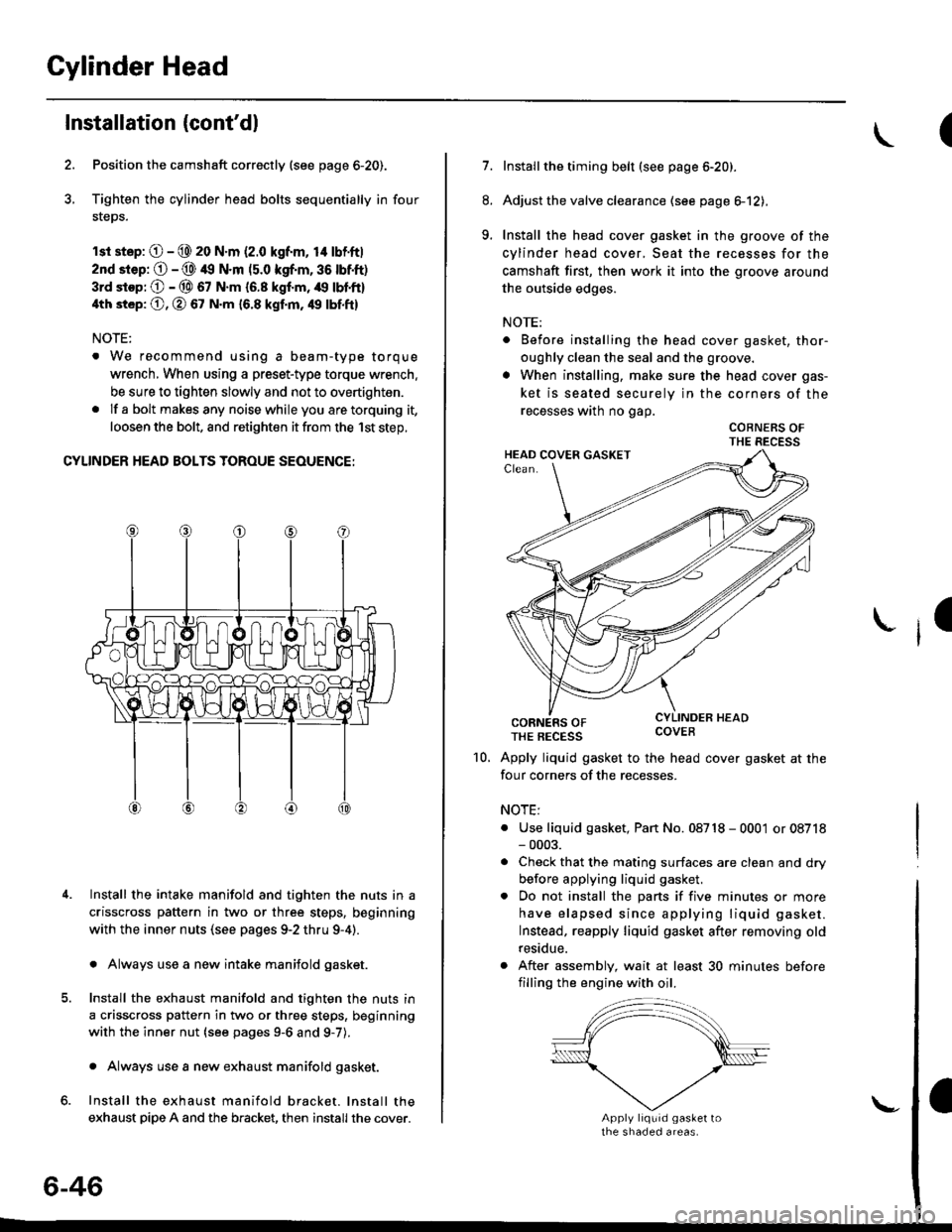
Tighten the cylinder head bolts sequentially in four
steps.
rsr st.p: O - @ 20 N.m (2.0 kgf.m, 14 lbf'ft|
2nd srep: O - @ 49 N.m (5.0 kgf.m, 36 tbtft)
3rd stop; O - @ 67 N.m {6.8 kgf.m, /r9 lbl'ft}
4th st6p: O, O 67 N.m 16.8 kgf.m, 49 tbf.ftl
NOTE:
. We recommend using a beam-type torque
wrench, When using a preset-type torque wrench.
be sure to tighten slowly and not to overtighten.
. If a bolt makesany noisewhileyou aretorquing it,
loosen the bolt, and retighten it from the 1st step,
CYLINDER HEAD BOLTS TOROUE SEOUENCE:
Install the intake manifold and tighten the nuts in a
crisscross pattern in two or three steps, beginning
with the inner nuts (see pages 9-2 thru 9-4).
. Always use a new intake manifold gasket.
Install the exhaust manifold and tighten the nuts in
a crisscross pattern in two or three steps, beginning
with the inner nut {see pages 9-6 and g-7).
. Always use a new exhaust manifold gasket.
Install the exhaust manifold bracket. lnstall the
exhaust pipe A and the bracket, then install the cover.
4.
6-46
\-
(
7.Installthe timing belt (see page 6-20).
Adjust the valve clearance (see page el2),
Install the head cover gasket in the groove of the
cylinder head cover, Seat the recesses for the
camshaft first, then work it into the groove around
the outside edges.
NOTE:
. Before installing the head cover gasket, thor-
oughly clean the seal and the groove.
. When installing, make sure the head cover gas-
ket is seated securely in the corners of the
recesses wath no gap.
COBNERS OFTHE RECESS
CORNERS OFTHE REcEss covEB
Apply liquid gasket to the head cover gasket at the
four corners of the recesses.
NOTE:
. Use liquid gasket, Pan No. 08718 - 0001 or 08718- 0003.
. Check that the mating surfaces are clean and dry
before applying liquid gasket.
. Do not install the parts if five minutes or more
have elapsed since applying liquid gasket.
Instead, reapply liquid gasket after removing old
residue.
. After assembly, wait at least 30 minutes before
filling the engine with oil.
8.
9.
I
10.
Page 194 of 2189
I
Cylinder Head
Installation
lnstall the cylinder head in the reverse order of removal:
NOTE:
. Always use a new head and manifold gasket.. The cylinder head gasket is a metal gasket, Take carenot to bend it.
. Rotate the crankshaft, set the No. 1 piston at TDC (seepage 6-63).
. Do not use the middle cover and lower cover forstorang removed items.. Clean the middle cover and lower cover before instal_lation.
o Replace any washers that are damaged or deteriorated.
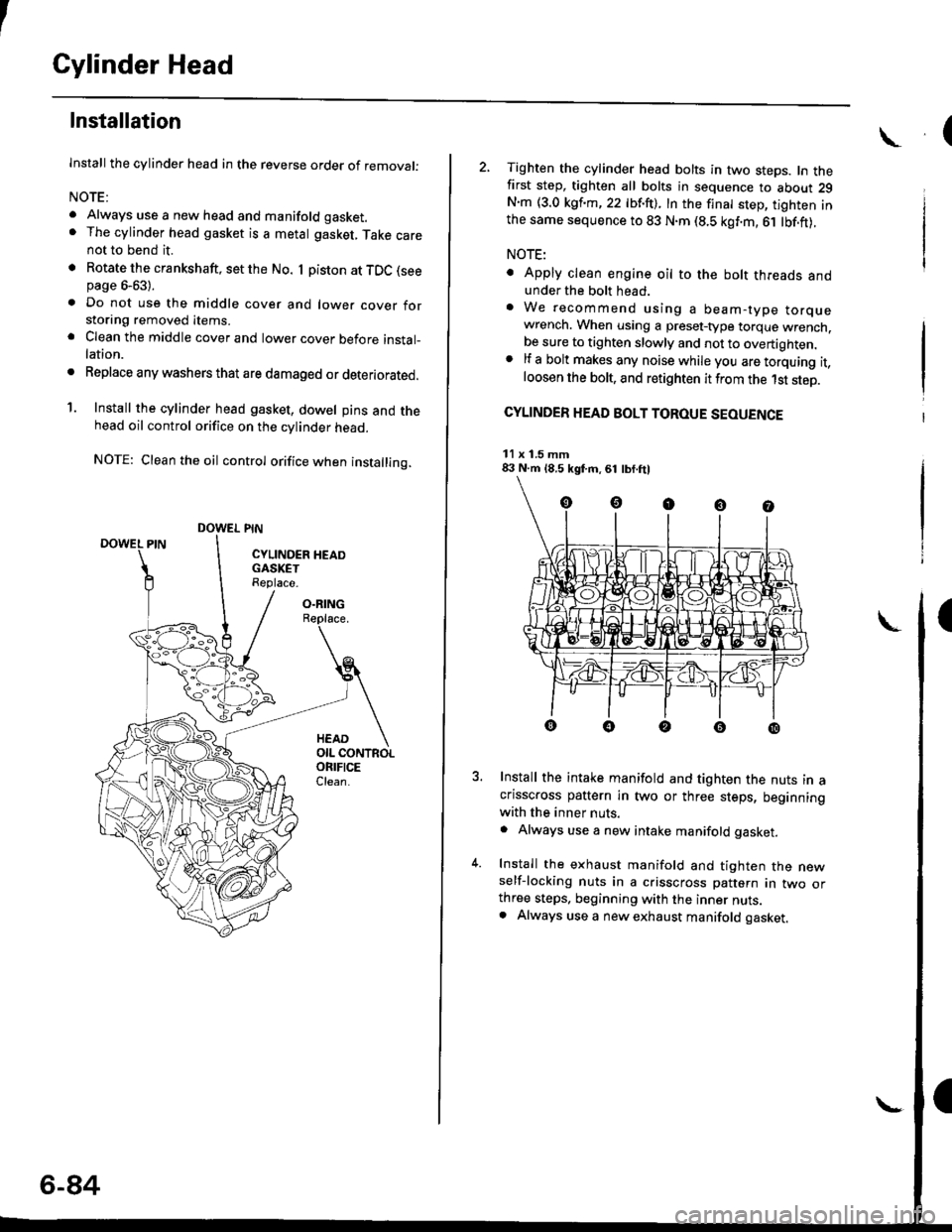
1. Install the cylinder head gasket, dowel pins and thehead oil control orifice on the cylinder head.
NOTE: Clean the oil control orifice when installing.
DOWEL PIN
6-84
2, Tighten the cylinder head bolts in two steps. In thefirst step, tighten all bolts in sequence to about 29N.m (3.0 kgf.m, 22 tbf.ftl. ln the final step, tighten inthe same sequence to 83 N.m (8.S kgf.m,6t lbf.ft).
NOTE:
. Apply clean engine oil to the bolt threads andunder the bolt head.. We recommend using a beam-type torquewrench. When using a preset-type torque wrench,be sure to tighten slowly and not to overtighten.. lf a bolt makes any noise while you are torquing it,loosen the bolt, and retighten it from the 1st step.
CYLINDER HEAD BOLT TOROUE SEOUENCE
11x 1.5 mm83 N.m 18.5 kgf.m, 61 tbf.ftl
Install the intake manifold and tighten the nuts in acflsscross pattern in two or three steps, beginningwith the inner nuts.. Always use a new intake manifold gasket.
Install the exhaust manifold and tighten the newself-locking nuts in a crisscross pattern in two orthree steps. beginning with the inner nuts.. Always use a new exhaust manifold gasket.
4.
Page 360 of 2189
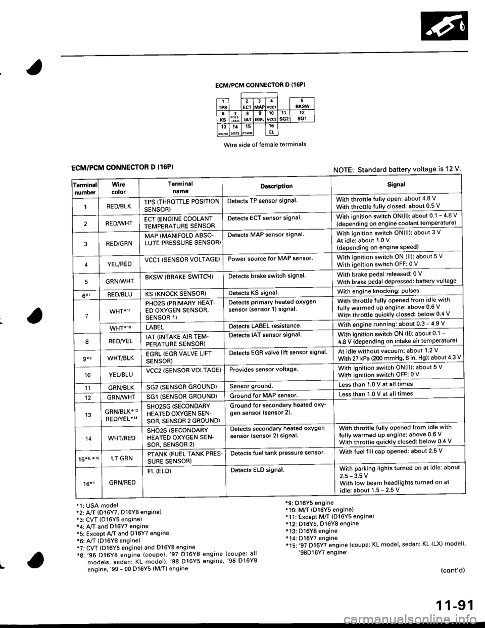
ECM/PCM CONNECTOR D I16P)
Wire side ot female terminals
ECM/PCM CONNECTOR D l16P)NOTE: Standard battery voltage is 12 V
Te.minalnumb€r
Wirecolor
Terminaln!meDor.riptionSignal
RED/BLKTPS (THROTTLE POSITION
SENSOR}
Detects TP sensor signal.With throttle fully open: about 4.8 V
With throttle fully closedl about 0.5 V
REDA/VHTECT {ENGINE COOLANTTEMPERATURE SENSORDetects ECT sensor signalWith ignition switch ON{ll): about 0.1 - 4 8 v
(depending on engine coolant lempe ratu re)
3RED/G RNMAP {MANIFOLD ABSO'LUTE PRESSURE SENSOR}Detects MAP sensor signal.With ignition switch ON(ll): about 3 V
At idle: about 1.0 V
{depending on engine speed)
YEUREDVCCl (SENSOR VOLTAGE)Power source lor MAP sensor.With ignition switch ON (ll): about 5 v
With ignition switch OFF: 0 V
5GRNMHTBKSW {BRAKE SWITCHIDetects brake switch signalWith brake pedal released: 0 v
With brake pedal depressed: baftery voltage
6*?RED/BLUKS {KNOCK SENSOR}Detects KS signal.With engine knocking: Pulses
1
PHO2S (PRIMARY HEAT-ED OXYGEN SENSOR,SENSOR 1)
Detects Primary heated oxygen
sensor (sensor 1l signal
With throttle fullv opened from idle with
Iully warmod up engine: above 0.6 V
With throttle quickly closed: below 0.4 v
LABELDetects LABEL resistanceWith engine r!nning:about 0.3 - 4.9 V
8RED//ELIAT (INTAKE AIR TEM-PERATURE SENSOR)
Detects IAT sensor signal.With ignition switch ON (ll): about 0 1 -
4.8 V {depending on intake air temperature)
9*lWHT/BLKEGRL iEGR VALVE LIFT
SENSOR)
Detects EGR valve lift sensor signalAt idle without vacuum: about'1 2 V
With 27 kPa (2OO mmHg,8 in. Hg): about 4 3 V
10YEUBLUVCC2 (SENSOR VOLTAGE)Provides sensor voltage,With ignition switch ON(ll): about 5 V
With ignition switch OFF:0 V
11GRN/BLKSG2 (SENSOR GROUND}Sensor ground.Less than 1.0 V at alltimes
12G RN,4/1r'HTSG1 (SENSOR GROUND)Ground for MAP sensor.Less than 1.0 V at alltimes
GRN/BLK*1?SHO25G (SECONDARY
HEATED OXYGEN SEN'
SOR, SENSOR 2 GROUND)
Ground for secondary heated oxy-
gen sensor (sensor 2).
14WHT/REDSH02S (SECONDARY
HEATED OXYGEN SEN'soR, sENsoR 2)
Detects secondary heated oxygen
sensor (sensor 2) signal.With throftle fully opened lrom idle with
fully warmed up engine: above 0.6 V
With throttle quickly closed: below 0.4 V
15|3. *15LT GRNPTANK {FUEL TANK PRES.
SURE SENSOR)
Detects fueltank prgssure sensor'With fuelfill caD opened: about 2.5 V
16*1GRN/RED
EL (ELD)Detects ELD signal.With parking lights turned on at idle: about
2.5 - 3.5 VWith low beam headlights turned on at
idle: about 1.5 - 2.5 V
*1: USA model*2r A/T (D16Y7, D16Y8 engine)*3: CVT (D16Y5 engane)*4: A,/T and Dl6Y7 engine*5: Except A/T and D16Y7 engine*6: A"/T (D16Y8 engine)i7: CVT (Dl6Y5 engine) and Dl6Y8 engine*8: .96 D16Y8 engine (coupei,'97 D16Y8 engine
models, sedanr KL model),'98 016Y5 engine,
engine, '99 - 00 D16Y5 (M/T) engine
*9: D16Y5 engine*10: M/T (D16Y5 engine)*11: Except M/T (Dl6Y5 engine)* 12r D16Y5. D16YB engine*13: D16Y8 engine*14: Dl6W engine*15: '97 D16Y7 engine (coupe: KL model, sedan: KL lLX) model),'98D16Y7 engine:(coupe: all'98 D16Y8
(cont'd)
1 1-91
Page 361 of 2189
Troubleshooting
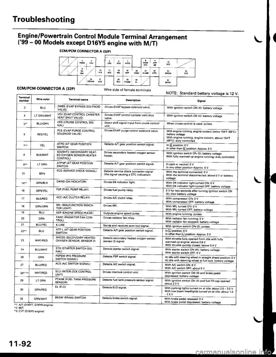
Engine/P_o,wertrain Control Module Terminal Arrangement('99 - 00 Models except Dl6Y5 engine with M/Tl
ECM/PCM CONNECTOR A (32P)Wire side ot temale terminalsNOTE:Standard battery voltage is l2 V
ECM/PCM CONNECTOR A I32PI
Sign!l
3BLU2WSS (EVAP 8YPAsS SOLENOIDDrives EVAP bypass solenoid vatve,With gn'tion swnch ON (lll banery votlage
LT GRN/I/VIITVSV {EVAP CONTNOL CANISTERVENTSHUTVALVE]Drives EVAP controt ca n isrer v€nt shutWilh ignilion switch ON {tl): b€ttery vottage
8LU/GNNC8S (CRUISE CONTSOL SIGOown shift signal inpot lrom c.uise conrrolWhen crurss control is used:purses
68ED/YELPCS {EVAP PURGE CONTROLSOTENOIOVALVE)Drives EVAP purge conrrol sotenoid vatve.With engine running, engine cootant, betow r54.F (6a,C):
With engine.unning, €ngine coolant, abov€ 154.F(68'C): duty conlrolled
YELATPD {AT GEAR POSITIONSWITCH)ootects A/T gear posnion swilch s,gnar.In otherthan @ posilion: Apprcx. 5 V
8BLK,IflHTSO2SHTC (SECONDARY HEATED OXYGEN SENSOS HEATEFCONTFOL)
Drives sscondary h€ared oxygen senso.Wilh isn,rion swirch ON (ll):banery votraseWith lully warm6d dp€ngire runn'ng:dury controled
LT GRNATPNP (AT GEAF POSITIONSWITCH)oereds A/T 9€a r position switch signat.In Parr or neulrsl:0 VIn anyother position approx.5 v
t088NSCS (SERVICE CHECK SIGNAL)Oetects ssruice check connecror signal(the signalcausing a OTC indication)with rh€ t6rminal connected: 0 vWith the rerm ina I disconneded: abour 5 V of ban€ry
GNN/BIKD4IND (D4INDICATON]Drives Oa indicaio. lighr.With D4 indicator lightturned ON: O VWith D4 indicator lightturned OFF: battery vo ttageG8N/YETFTF (FUEL PUI\,4P SELAY)Orivos tuel pump relay,0V for two s€conds lfrer turnrng rgnilior swtcn ON(ll), then batt€ry voltage11BTI(REDACC (Al/C CTUTCH SELAY)Drives A./C clutch reray.With compressor ON:O VWilh comp.ssor OFF; battery vottage18GFN/OFNMI! (A,IAIFUNCTION INDICA.TOF LIGHT)With MlLturned ON:0 VWith l\,llL tornod OFF|batrery votrsge198tuNEP (ENGINE SPEED PUTSEIOulputs6ngine speed pulse,Wilh engin6.unning: putses
20GFNFANC {SADIATOR FAN CONTnoL)Orives radiarortan relay.Wirh r.distor t6n running:OVWith radiatortan stopped: banery vottage21ELUA/ELK LINESends and r€ceives s.an lool signal.With ignition switch ON (ll):p!ts€s
22'lBLUATP L {AT GEAS POSITIONswtTcH)Oelocis A"/T gear posirion switch siSnat.In othfflhan E position: Apprcx. 5 V
23SHO25 (SECONOARY HEATEDOXYCEN SENSOR, SENSOF 2)Detects secondsry hoar€d oxygen sensorWith lhronle f! lly or'6ned from idte with fu ywarmod up engine: above 0.6 vWiih th.onl6 quickb, closd:below 0,4 V24STS ISTAFTEN SWITCH SIGDebcrs staner switch signat.Wirh srarterswitch ON (tttJ: batteryvottogeWith sraftsr cwirch OFF:0 V26GFNPSPSW iPlS PNESSURESWITCII SIGNAL)Derecrs PSP switch signat.Atidle with steoring wheolin srraightahead position: O VAt idl6with steering wheetal fult lock: barery vo ttags27BLU/REOACS (AJC SWITCH SIGNALJOer*ts ,ay'C swirch signat.Wiih ty'C switch ON;0VWilh Ay'C switch OFF|aboor 5VWHT/REDSLU iINTERLOCK CONTROIUNIT)Drivos interloct control unit.With ignltion switch ON (ll)and brake pedaldepresed: batlory volrage29LT GRNPTANK (FUEL TANK PFESSUEESENSOR)Oer6ds lu€l tank pr€ssura sonsor signat.Wilh ig.rrrd swirch ON rttr and fuetti
cap ooen6d.
30GRN/FEOEr (ELOIWith parking lighlsrurned on ar idteiaboui 2.5- 3.S VWirh low beam he€dlig hts turnqd on ai idts: aboul 1.52.5 V32GRN/'WHTAKSW (BFAKE SWITCH)Detets brak€ swrtch signEt,With brake pedal r6l€ased:0 VWhh brake pedaldepres*d: battery voltEse'1:A./T (D16Y7, D16Y8 engine)*2: rvt/T13: CVT (D16Y5 engine)
11-92
Page 1122 of 2189
Steering Gearbox
Installation (cont'dl
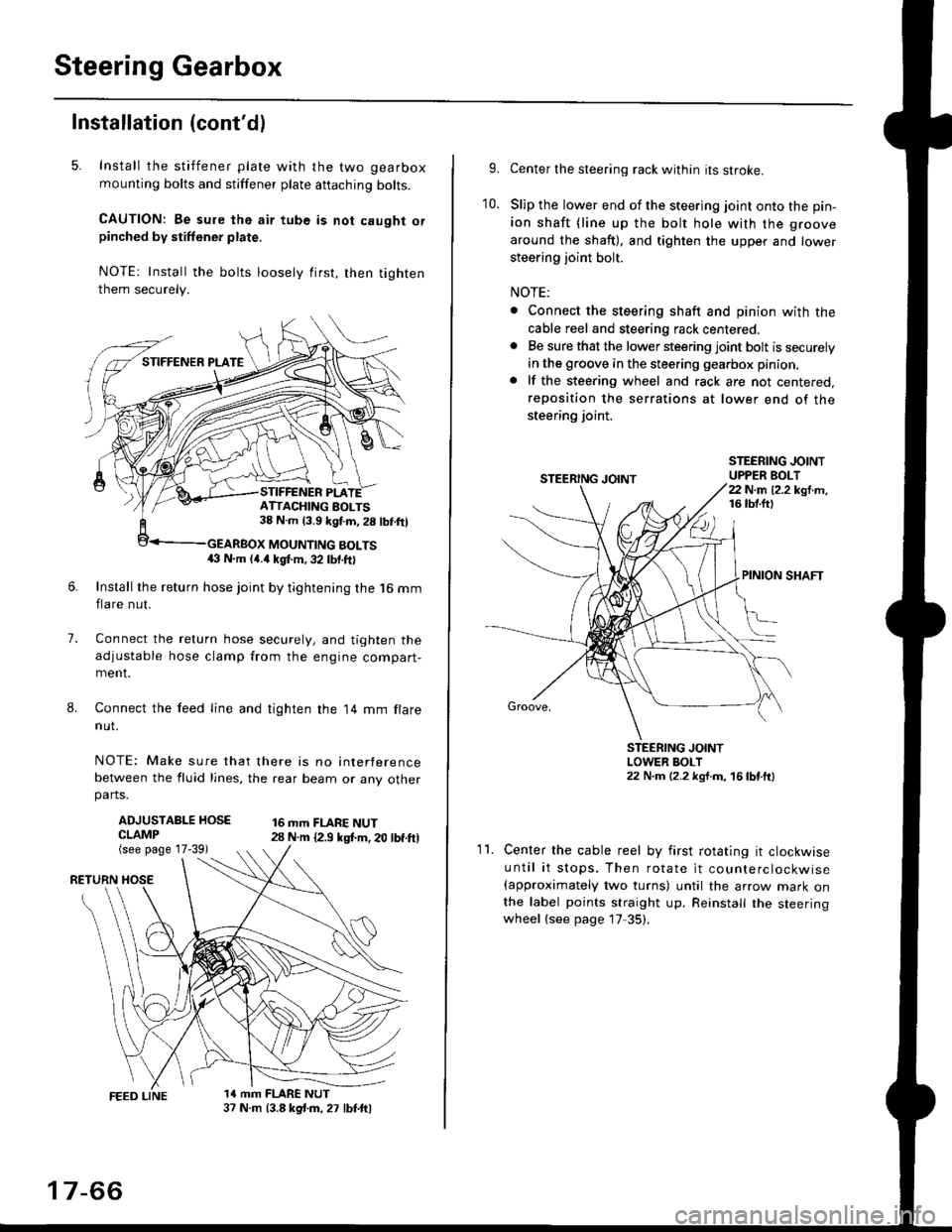
5. Install the stiffener plate with the two gearbox
mounting bolts and stiffener plate aftaching bolts.
CAUTION: Be sure the air tube is not caught orpinched by stiffener plate,
NOTE: Install the bolts loosely first, then tighten
them securely.
7.
8.
6.Install the return hose joint by tightening the l6 mm
flare nut.
Connect the relurn hose securely, and tighten the
adjustable hose clamp from the engine compart-ment.
Connect the feed line and tighten the 14 mm flare
nut.
NOTE: Make sure that there is no interference
between the fluid lines, the rear beam or any otherparts.
ADJUSTABLE HOSECLAMP(see page 17-39)
16 mm FLARE NUT28 N.m {2.9 ksl.m. 20 lbf.ft)
RETURN
1a mm FLARE NUT37 N.m (3.8 kg{.m, 27 lbt.ftl
ATTACHING AOLTS38 N.m 13.9 kgf.m, 28 lbf.ftl
MOUNTING BOLTS(} N.m (4.a kgt m, 32 lbf.ftl
17-66
9.Center the steering rack within its stroke.
Slip the lower end of the steering joint onto the pin-
ion shaft (line up the bolt hole with the groove
around the shaft), and tighten the upper and lower
steering joint bolt.
NOTE:
. Connect the steering shaft and pinion with the
cable reel and steering rack centered.. Be sure that the lower steering joint bolt is securely
in the groove in the steering gearbox pinion.
. lf the steering wheel and rack are not centered,
reposition the serrations at lower end of the
steering joint.
10.
STEERING JOINTUPPER BOLT22 N.m (2.2 kgf.m,16 tbt.ftl
PINION SHAFT
Groove,
STEERING JOINTLOWER BOLT22 N.m (2.2 kgt.m, 16lbtttl
11.Center the cable reel by first rotating it clockwise
until it stops. Then rotate it counterclockwise(approximately two turns) until the arrow mark onthe label points straight up. Reinstall the steeringwheel (see page 17 35).
Page 1535 of 2189
lr-
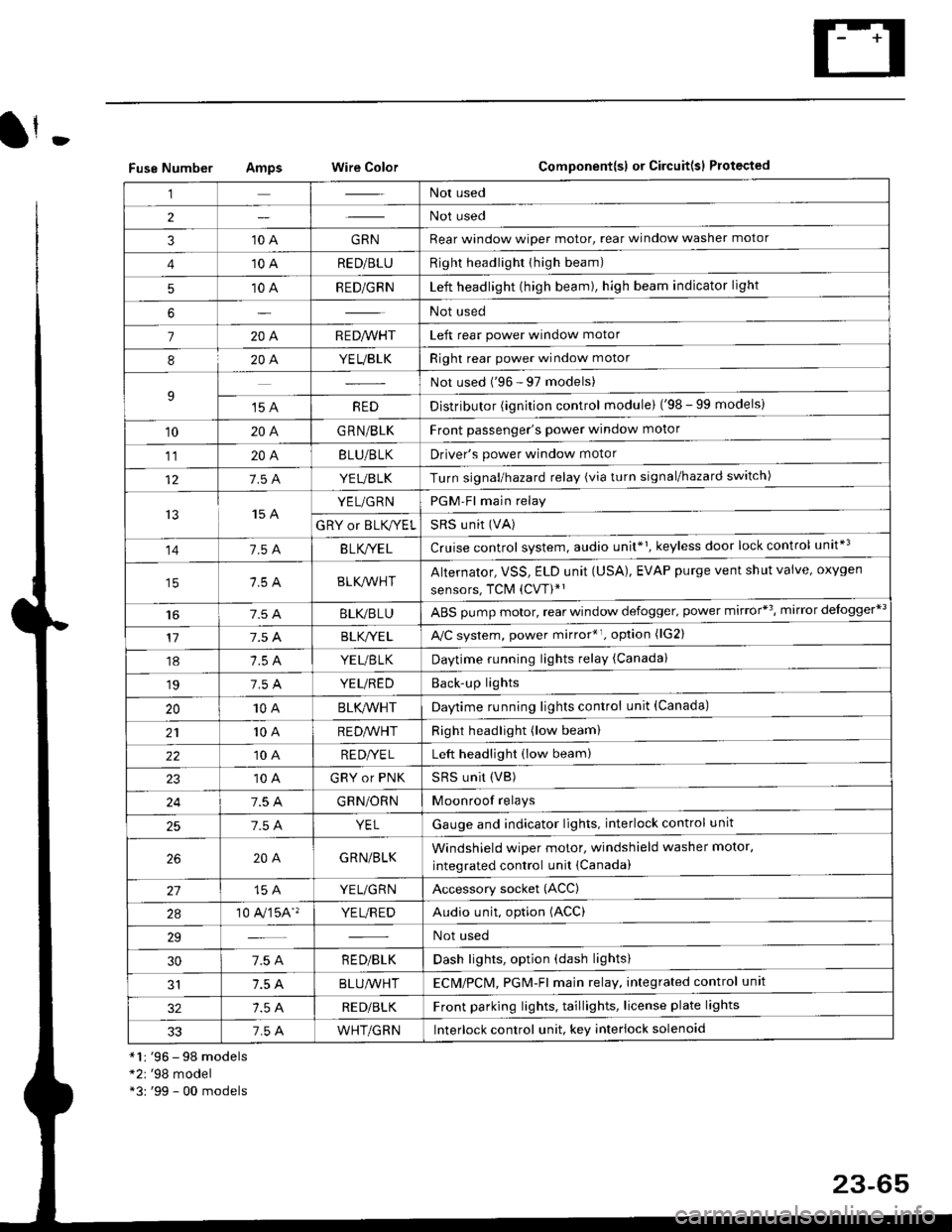
Fuse NumberAmpswire ColorComponent{sl or Circuit(sl Protected
*1r '96 - 98 models*2r '98 model*3: '99 - 00 models
,lNot used
2Not used
310 AGRNRear window wioer motor, rear window washer motor
410 ARED/BLURight headlighr thigh beam)
510 ARED/GRNLeft headlight (high beam), high beam indicator light
6Not used
7204R E D/VVHTLeft rear power window motor
820A.YEUBLKRight rear power window motor
9Not used ('96 - 97 models)
't5 AREDDistributor (ignition control module) ('98 - 99 models)
10204G RN/BLKFront passenger's power window motor
1120ABLU/BLKDriver's power window motor
127.5 AYEUBLKTurn signal/hazard relay (via turn signal/hazard switch)
t515 AYEL/GRNPGM-Fl main relay
GRY or BLK,^/ELSRS u nit (VA)
141.54B LK/YE LCruise control system, audio unit*1, keyless door lock control unit*3
BLK/lr'r'HTAlternator, VSS, ELD unit (USA), EVAP purge vent shut valve, oxygen
sensors, TCM (CVT)*'
t6BLI(,/BLUABS pump motor, rear window defogger. power mirror*3, mirror delogger*3
177.5 ABLK,/YE LA,/C system, power mirror*r. option (lG2)
18YEUBTKDaytime running lights relay (Canada)
197.5 AYEUREDBack'up lights
2010ABLK/VVHTDaytime running lights control unit (Canada)
2110 AREDA/VHTRight headlight (low beam)
2210 ARE DI/E LLeft headlight (low beam)
10 AGRY or PNKSRS UNit (VB)
247.5 AGRN/ORNMoonroof relays
257.5 AYELGauge and indicator lights. interlock control unit
204GRN/BLKWindshield wiper motor, windshield washer motor,
integrated control unit {Canada)
15 AYEL/GRNAccessory socket (ACC)
2a10 A,/'�]5A''YE L/R EDAudio unit, option (ACC)
29Not used
307.5 AR ED/BLKDash lights, option (dash lights)
1.5 ABLUA/VHTECM/PCl\4, PGM-Fl majn relay, integrated control unit
RED/BLKFront parking lights, taillights, license plate lights
337.5 AWHT/GRNlnterlock control unit. key interlock solenoid
23-65
Page 1543 of 2189
!t
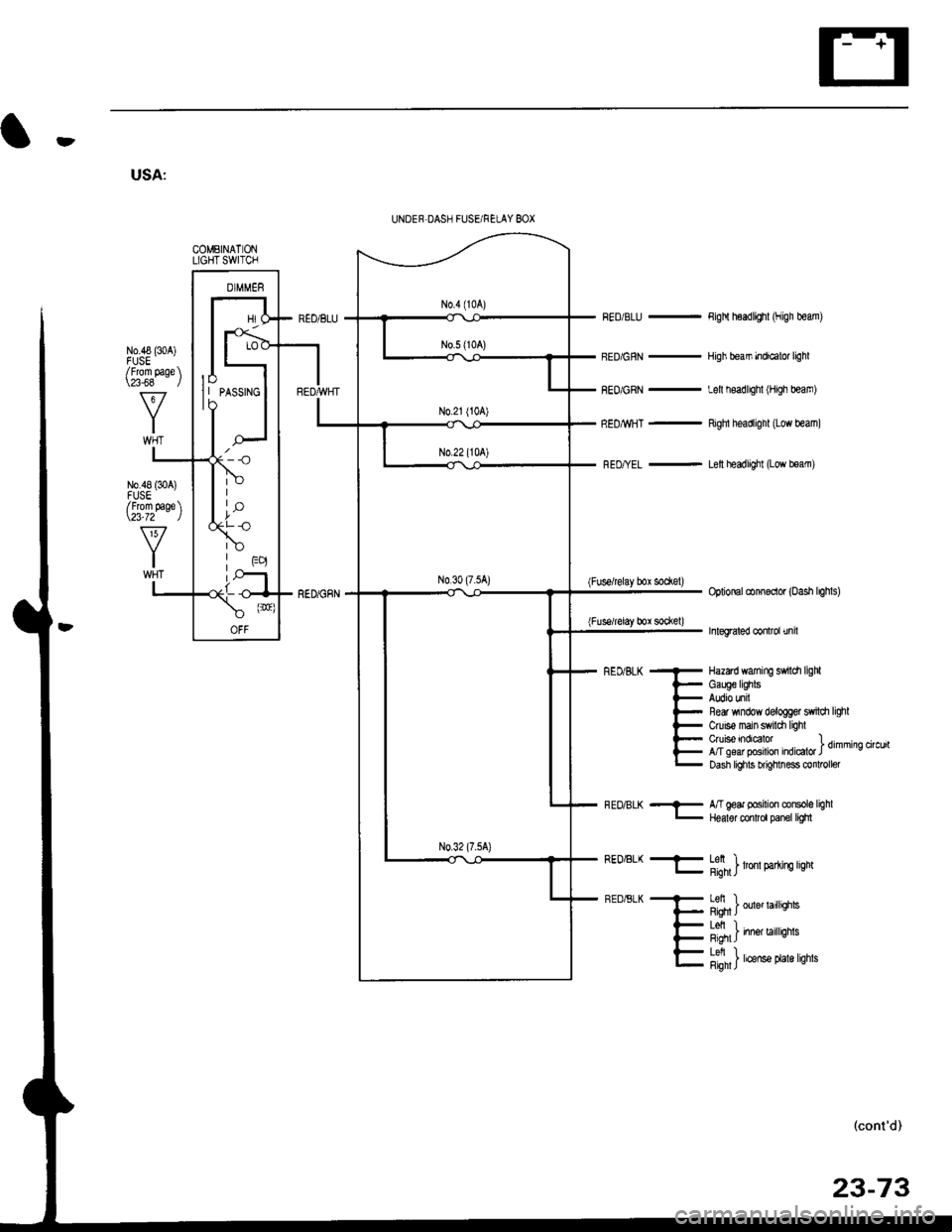
USA:
UNDER,DASH FUSEi RELAY BOX
COMEINATONLIGHT SWITCH
No.48 (304)FUSE/Frcm page \\23{8 /
No.a8 G0A)FUSE/Frcm page \\23-72 )
lo
I ' to"'to
RED/BLU _
BED/GRN _
FEO/GRN -
REDMHT -
REo/{EL -
Figltl h6adlighl (High beam)
High beam indi€tor light
Lefl headlighl (High beam)
Right headlighl (Low beam)
Letl headlighl (Low beam)
(Fuse/relay box socl(el)
(Fuss/relay box sockel)
FEo/BLK t
RED/BLK t
optioml @nn6clor loash hghls)
InEgraled control unil
Hazard waming sMch ligldGaugelighlsAudio unilnear wndow delog0er swild lighlCruiso main switdr lighlctuis€ndrcalot .. ]crmminocircu,tA/ | qsar posrrcn nor@Ior JDash lighls brighhess mnlroller
l'/T gea. pGilion console lighlHeald conlrol panel ligtn
::: I lronl oarkino liohlHqm,
n-'i6 J *t"' t"itt'9t'6
n-,sh j inn"t u'll'gl't'
:: 1 | hcense Dlale liohtsHgnr i
(cont'd)
23-73
Page 1544 of 2189
Power Distribution
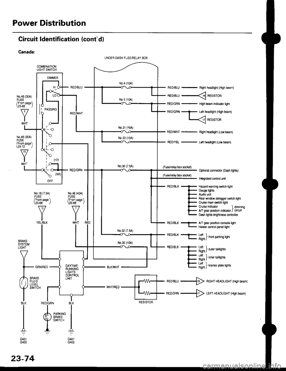
Circuit ldentification (cont'd)
Canada:
COMBINATIONLIGHT SWITCH
N0.48 {30A)
RED/BLU - Right headlighl (High boam)
FEDiBLU ----< REstsTOR
REo/GRN - HiJh beam indicator lighl
BEo/GRN - Left headlighl iH,gh beam)
L
FEo/YEL - L€ll headlight (Low beam)
(Fuse/lelay box sockel)Optional conneclor (oash lighs)
Inleg6led conlrcl unil
- Hazard wanirE swilch lighl
i- Gauge lEhts
l- Audio unil
l- Re& Yrindow delogg8r swili
t- Ctuise main swrdr ligh
l- C/uise indEator l
E g"ffiry:'l,:1':::1
Refi window delog$r swildr light
Ctuise indicalor 1 dimming,T geal posilion indicator J circu(Dasn lghls brignmess co oller
BRAKESYSTEMLIGHT
V
I
l- GFf
,,4,,0*,lf tIFLUDII ,j I LEVEL
Y
SWTCH
I8LKI
I
I
I:
G401G402
REo/BLK - l/T ged position console lqhl- Hqalor codrot panel tighl
REO/BLK -F- Lefi ) .l- g;n1J lron 9arrn! qm
FEDiBLK + Letl I
F Rqn J ouer larrqns
- I Al, I
{- i'-;*; inne' raittiotts
E fifi]t'"nt"o't't'sn"
*ro,rru -$ RcHT HEADLIGHT (Hrgh beam)
BEDiGRN -+ LEFI H EADLIGHT (High beam)
I BLK
IIPARKING IEFAKE IswrrcH I
I:
G401G402
UNDER,DASH FUSE/RELAY 8OX
lo| | PASSTNGto
/Fforn page\\a-68 l
N0.48 {304)FUSE/From page\\23-72 )
N0.18 (7.54)FUSE/From page \\?3-69 J
v
YIYEUBLK
N0.48 (40A)FUSE/From paqe \\23-68 - ,/
RED6RN
23-74
Page 1607 of 2189
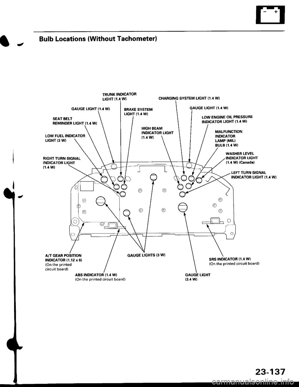
JBulb Locations {Without Tachometer)
TRUNK INDICATORLIGHT {1.i1W}
.4 Wl
CHARGING SYSTEM LIGHT 11,4 W}
LTGHT (1.4 W)GAUGE LIGHT
SEAT BELTREMINDER LIGHT (1.4 WI
LOW ENGINE OIL PRESSUBE
INDICATOB LIGHT (1.4 WI
LOW FUEL INDICATORLrGl{T (3 W)
RIGHT TURN SIGNALINOICATOR LIGHT
(1.1Wt
GAUGE LIGHTS {3 WI
WASHER LEVELINDICATOR LIGHT{1.4 W} lcanad.l
HIGH BEAMINDICATOR LIGHTMALFUNCTIONINDICATORLAMP (MIL)
BULB {1.4 WI
{1.ilW)
LEFT TURN SIGNALINDICATOR LIGHT {1.4 WI
A/T GEAR POSITIONINDICATOR (1.12 x 6)(On the printed
circuit board)
sRs TND|CATOR 11.4 W)
{On the Drinted circuit board}
aBs tNDtcAToR t1.4 W)(On the printed circuit board)(3.{ Wt
o/ o \7 o
23-137
Page 1636 of 2189
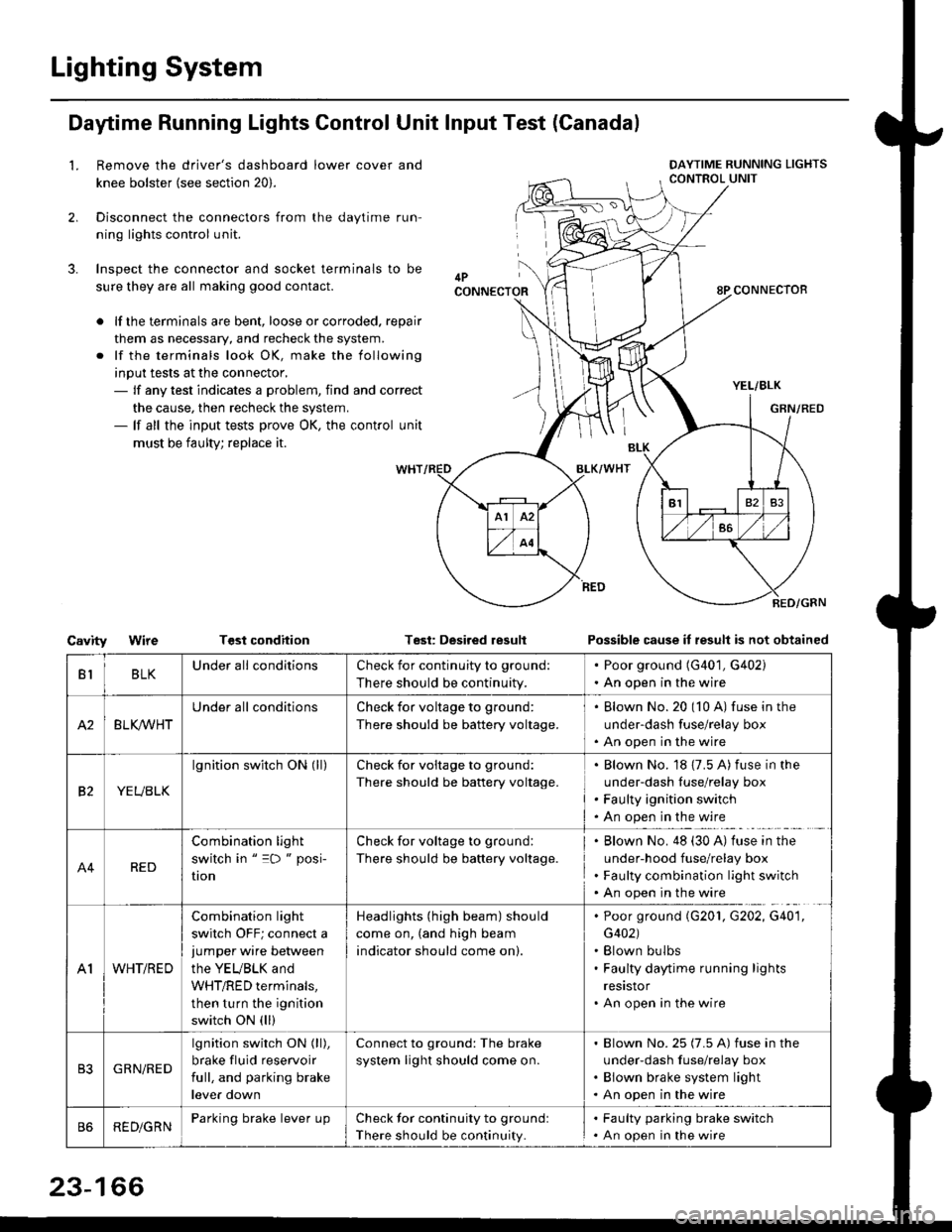
Lighting System
Daytime Running Lights Control Unit Input Test (Canadal
2.
3.
LRemove the driver's dashboard lower cover and
knee bolster (see section 20).
Disconnect the connectors from the daytime run-
ning lights control unit.
Inspect the connector and socket terminals to be
sure they are all making good contact.
lf the terminals are bent, loose or corroded. repair
them as necessary, and recheck the system.
lf the terminals look OK, make the following
input tests at the connector,- lf any test indicates a problem, find and correct
the cause, then recheck the system.- lf all the input tests prove OK, the control unit
must be faulty; replace it.
CavityWireTGst conditionTest: Desired resultPossible cause it result is not obtained
BLKU nderall conditionsCheck for continuity to g.ound:
There should be continuity.
. Poor ground (G401, G402). An open in the wire
A2BLK /VHT
Underall conditionsCheck for voltage to ground:
There should be battery voltage.
Blown No.20 (10 A) fuse in the
under-dash fuse/relay box
An open in the wire
etYEUBLK
lgnition switch ON (ll)Check for voitage to ground:
There should be battery voltage.
Blown No. 18 {7.5 A) fuse in the
under-dash luse/relay box
Faulty ignition switch
An open in the wire
A4RED
Combination light
switch in " =D " posi-
UOn
Check for voltage to ground:
There should be battery voltage.
Blown No. 48 (30 A) tuse in the
under-hood fuse/relay box
Faulty combination light switch
An open in the wire
A1WHT/RED
Combination light
switch OFF; connect ajumper wire between
the YEUBLK and
WHT/RED terminals,
then turn the ignition
switch ON (ll)
Headlights (high beam) should
come on, (and high beam
indicator should come on).
. Poor ground (G201, G202, G40'1,
G402). Blown bulbs. Faulty daytime running lights
resrstor. An open in the wire
GRN/RED
lgnition switch ON (ll),
brake fluid reservoir
full, and parking brake
lever down
Connect to ground: The brake
system light should come on.
Blown No.25 (7.5 A) fuse in the
under-dash f use/relay box
Blown brake system light
An open in the wire
REDiGRNParking brake lever LrpCheck for continuity to groundl
There should be continuity.
. Faulty parking brake switch. An open in the wire
23-166