4WD MITSUBISHI OUTLANDER PHEV 2014 Owner's Manual (in English)
[x] Cancel search | Manufacturer: MITSUBISHI, Model Year: 2014, Model line: OUTLANDER PHEV, Model: MITSUBISHI OUTLANDER PHEV 2014Pages: 442, PDF Size: 19.04 MB
Page 6 of 442

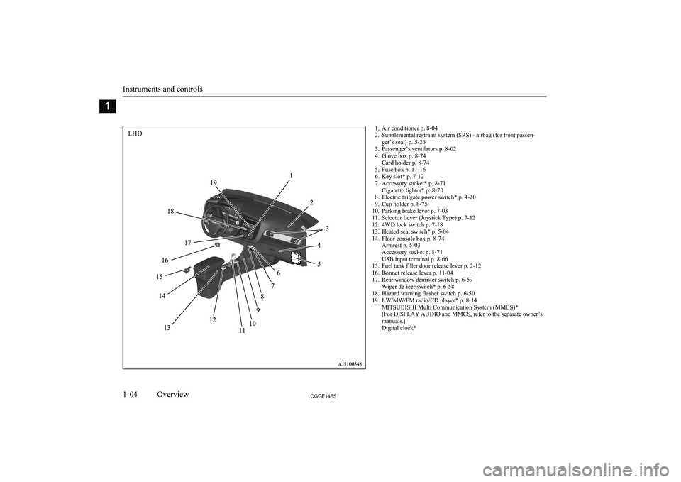
1. Air conditioner p. 8-04
2. Supplemental restraint system (SRS) - airbag (for front passen- ger’s seat) p. 5-26
3. Passenger’s ventilators p. 8-02
4. Glove box p. 8-74 Card holder p. 8-74
5. Fuse box p. 11-16
6. Key slot* p. 7-12
7. Accessory socket* p. 8-71 Cigarette lighter* p. 8-70
8. Electric tailgate power switch* p. 4-20
9. Cup holder p. 8-75
10. Parking brake lever p. 7-03
11. Selector Lever (Joystick Type) p. 7-12
12. 4WD lock switch p. 7-18
13. Heated seat switch* p. 5-04
14. Floor console box p. 8-74 Armrest p. 5-03
Accessory socket p. 8-71
USB input terminal p. 8-66
15. Fuel tank filler door release lever p. 2-12
16. Bonnet release lever p. 11-04
17. Rear window demister switch p. 6-59 Wiper de-icer switch* p. 6-58
18. Hazard warning flasher switch p. 6-50
19. LW/MW/FM radio/CD player* p. 8-14 MITSUBISHI Multi Communication System (MMCS)*
[For DISPLAY AUDIO and MMCS, refer to the separate owner’s
manuals.]
Digital clock*
Instruments and controls
1-04OGGE14E5Overview1LHD
Page 7 of 442

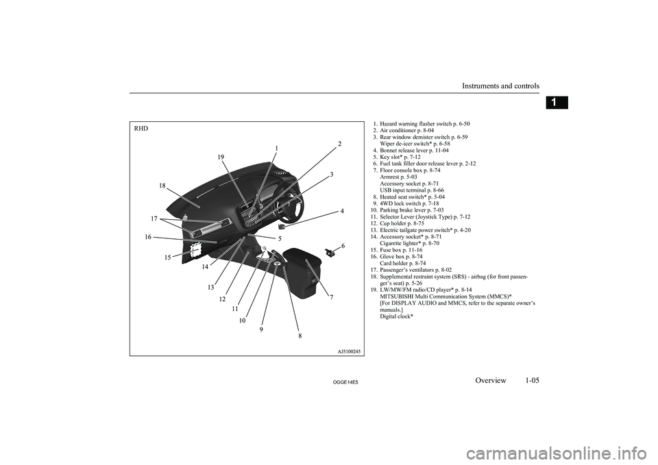
1. Hazard warning flasher switch p. 6-50
2. Air conditioner p. 8-04
3. Rear window demister switch p. 6-59 Wiper de-icer switch* p. 6-58
4. Bonnet release lever p. 11-04
5. Key slot* p. 7-12
6. Fuel tank filler door release lever p. 2-12
7. Floor console box p. 8-74 Armrest p. 5-03
Accessory socket p. 8-71
USB input terminal p. 8-66
8. Heated seat switch* p. 5-04
9. 4WD lock switch p. 7-18
10. Parking brake lever p. 7-03
11. Selector Lever (Joystick Type) p. 7-12
12. Cup holder p. 8-75
13. Electric tailgate power switch* p. 4-20
14. Accessory socket* p. 8-71 Cigarette lighter* p. 8-70
15. Fuse box p. 11-16
16. Glove box p. 8-74 Card holder p. 8-74
17. Passenger’s ventilators p. 8-02
18. Supplemental restraint system (SRS) - airbag (for front passen- ger’s seat) p. 5-26
19. LW/MW/FM radio/CD player* p. 8-14 MITSUBISHI Multi Communication System (MMCS)*
[For DISPLAY AUDIO and MMCS, refer to the separate owner’s
manuals.]
Digital clock*
Instruments and controls
1-05OGGE14E5Overview1RHD
Page 134 of 442

1- NORMAL indicator display screenDisplayed when the ECO mode switchand 4WD lock switch are OFF.
2- ECO mode indicator display screen Displayed when the ECO mode switch isON and the 4WD lock switch is OFF.
3- ECO LOCK indicator display screen Displayed when the ECO mode switchand 4WD lock switch are ON.
4- 4WD LOCK indicator display screen Displayed when the ECO mode switch isOFF and the 4WD lock switch is ON.→ “ECO mode switch” on page 6-51
→ “4WD lock switch” on page 7-18
5- Battery charge mode display screen
® p. 7-22
6- Battery save mode display screen
® p. 7-217- mark display screen ® p. 6-10
8- Forward Collision Mitigation System
(FCM) OFF display screen* ® p. 7-55
9- Lane Departure Warning (LDW) display
screen* ® p. 7-61
10- Cruise control display screen*
® p. 7-34
11- Adaptive Cruise Control System (ACC)
display screen* ® p. 7-43
12- Speed limiter display screen ® p. 7-38
13- Drive battery level display screen
® p. 6-10
14- Odometer ® p. 6-12
15- Information screen ® p. 6-08
16- Select position indicator ® p. 7-14
17- Fuel remaining display screen
® p. 6-1018- Outside temperature display screen
® p. 6-11Multi information display
switch
E00520001764
Each time the multi information display
switch is operated, the buzzer sounds and the multi information display changes betweeninformation such as warnings, tripmeter,
average fuel consumption, EV cruising range,
total cruising range, EVHV driving rate, en- ergy flow, etc.
Multi information display
6-04OGGE14E5Instruments and controls6
Page 168 of 442

ScreenSystem operation statusReferencelWhen charging of the drive battery is
completed.l Refer to “Charging” on page 3-02.lWhen the mode is changed by the opera-
tion of the 4WD lock switch or ECO mode
switch.l Refer to “ECO mode switch” on page
6-51.
l Refer to “4WD lock switch” on page
7-18.
l Refer to “When the ECO mode switch is
ON” on page 7-19.
Indication lamp, warning lamp, and information screen display list
6-38OGGE14E5Instruments and controls6
Page 207 of 442

To increase generative force
Each time you pull the - (DOWN) paddle to-
wards you, the regenerative brake force rises one level.
To return to the normal regen-
erative brake force level of B2
Pull the + (UP) paddle for approx. 2 seconds
or longer. 2 seconds or longer. The select lev- er position indicator displays “D”.
S-AWC (Super All Wheel
Control) E00622601097
S-AWC is an integrated vehicle dynamics
control system that helps enhance driving
performance, cornering performance, and ve-
hicle stability over a wide range of driving conditions through integrated management of the twin motor 4WD, the AYC (Active Yaw
Control), the ABS and the ASC.
CAUTIONl Do not over-rely on the S-AWC. Even the S-
AWC cannot prevent the natural laws of
physics from acting on the vehicle. This sys- tem, like any other system, has limits and
cannot help you to maintain traction and
control of the vehicle in all circumstances. Reckless driving may lead to accidents. It is the driver’s responsibility to drive carefully.
This means taking into account the traffic,
road and environmental conditions.
Twin Motor 4WD
This system improves vehicle stability per-
formance and fuel economy performanceduring acceleration and deceleration by mo-
tors provided at front and rear wheels, re- spectively, controlling the distribution of a
drive force between the front and rear wheels optimal for the operation of the driver.
Active yaw control system
(AYC)
E00622801044
The AYC is a system, with a left-right differ- ential limiting function and yaw control func-
tion, that controls the left-right driving/brak-
ing force by managing the brake.
S-AWC (Super All Wheel Control)
7-17OGGE14E5Starting and driving7
Page 208 of 442

CAUTIONlControl of the braking force does not en-
hance the stopping performance of the vehi-
cle, therefore, pay careful attention to the safety of your surroundings when driving.
Left-right differential limiting
function
The left-right differential limiting function is
a function that enhances driving performance and vehicle stability by preventing idle spin-
ning of a wheel when driving on a slippery road or when the road surfaces of left andright wheels are different.
Yaw control function
The yaw control function is a function thatenhances vehicle cornering performance and vehicle stability with management of vehicle
turning power (yaw moment) by controlling the brake force when the vehicle does not
turn in response to steering input, such as
when the steering wheel is turned quickly or when driving on a slippery road.
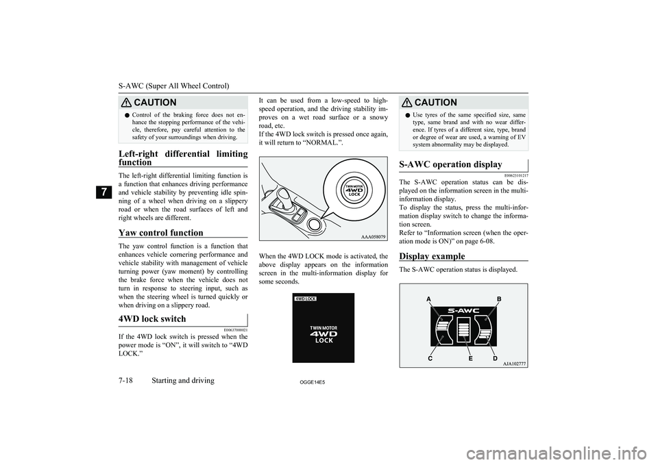
4WD lock switch
E00637000021
If the 4WD lock switch is pressed when the
power mode is “ON”, it will switch to “4WD LOCK.”
It can be used from a low-speed to high-
speed operation, and the driving stability im- proves on a wet road surface or a snowyroad, etc.
If the 4WD lock switch is pressed once again, it will return to “NORMAL.”.
When the 4WD LOCK mode is activated, the
above display appears on the information
screen in the multi-information display for some seconds.
CAUTIONl Use tyres of the same specified size, same
type, same brand and with no wear differ- ence. If tyres of a different size, type, brandor degree of wear are used, a warning of EVsystem abnormality may be displayed.S-AWC operation display
E00623101217
The S-AWC operation status can be dis-
played on the information screen in the multi-
information display.
To display the status, press the multi-infor-
mation display switch to change the informa- tion screen.
Refer to “Information screen (when the oper- ation mode is ON)” on page 6-08.
Display example
The S-AWC operation status is displayed.
S-AWC (Super All Wheel Control)
7-18OGGE14E5Starting and driving7
Page 209 of 442

Yaw control function display
The amount of the yaw moment is displayed
as a bar graph.
A,D-Clockwise yaw moment about the vehicle’s center of gravityB,C-Anticlockwise yaw moment about
the vehicle’s center of gravity
Torque distribution function display
The torque distribution between the front and rear wheels is displayed in section E of the
meter as a bar graph.
WARNINGl Always concentrate on your driving first.
Keep your eyes and mind on the road.
Distractions while driving can lead to an accident.When the ECO mode switch is
ON
E00636501026
While the drive mode is in the “4WD
LOCK” position, if the ECO mode switch is switched ON, the drive mode will be changed to “ECO LOCK” mode.
If the ECO mode switch is switched OFF, the
drive mode will be returned to “4WD LOCK” mode.
Refer to “ECO mode switch” on page 6-51.
4-wheel drive operation
E007606602083
Your vehicle has been designed primarily foruse on paved roads.
But its unique 4-wheel drive system allows
you to occasionally travel on unpaved roads, to campgrounds, picnic sites, and similar lo-
cations.
Not only does this ensure better handling on
dry, paved roads but also permits better trac-
tion when driving on slippery, wet or snow- covered roads and when moving out of mud.
But it is not suitable for heavy off road use or
towing in rough conditions.
It is particularly important to note that 4-
wheel drive may not give sufficient hill
climbing ability with the regenerative brake on steep slopes. You should try to avoid driv- ing on steep slopes.
Also, you must exercise caution when driving on sand and mud and when driving through
water because sufficient traction may not be
available in certain circumstances.
Please avoid driving the vehicle through
areas where the tyres may get stuck in deep sand or mud.WARNINGl Do not over-rely on the 4-wheel drive ve-
hicles. Even 4-wheel drive vehicles have
limits to the system and ability to main- tain control and traction. Reckless driving may lead to accidents. Always drive care-
fully, taking account of the road condi-
tions.
l Improperly operating this vehicle on or
off-paved roads can cause an accident or
rollover in which you and your passengers
could be seriously injured or killed.
• Follow all instructions and guidelines in
the owner’s manual.
• Keep your speed low and do not drive
faster than conditions allow you to.
4-wheel drive operation
7-19OGGE14E5Starting and driving7
Page 369 of 442

CAUTIONlThe impact on tyres and/or wheels when
driving on a bumpy or rutted road can dam-
age the tyre and/or wheel.
This vehicle is intended for driving mainly
on roads with firm surface.
4WD system makes it possible to drive on roads without special coverage, on flat and
firm surfaces. Please, remember that off-road ability of your vehicle is limited. Your vehi-
cle is not intended for driving in heavy off-
road terrain, overcoming the rugged terrain, deep ruts, etc.
The manufacturer of the vehicle is proceed- ing from the following assumption: if the
driver makes the decision to keep driving un-
der conditions mentioned above, he takes all actions at own risk, aware of the possibleconsequences.
Operation under adverse driving conditions
9-23OGGE14E5For emergencies9
Page 389 of 442

Snow traction device (tyrechains)
E01002103020
If snow traction device (tyre chains) have to
be used, ensure that they are fitted only on
the drive wheels (front) in accordance with
the manufacturer’s instructions.
On 4WD vehicles in which the driving power is distributed preferentially to the front wheels, ensure that the snow traction device
(tyre chains) are fitted on the front.
Use only snow traction device (tyre chains) which are designed for use with the tyresmounted on the vehicle: use of the incorrect
size or type of snow traction device (tyre
chains) could result in damage to the vehicle body.
Contact a MITSUBISHI MOTORS Author-
ized Service Point before putting on snow traction device (tyre chains). The max. snowtraction device (tyre chains) height is as fol- lows.
Tyre sizeWheel sizeMax. snow
traction de- vice (tyrechains)
height [mm]215/70R16 100H16 x 6 1/2 J
16 x 6 1/2 JJ9 mmTyre sizeWheel sizeMax. snow
traction de- vice (tyrechains)
height [mm]225/55R18 98H18x7 J
When driving with a snow traction device
(tyre chains) on the tyres, do not drive faster than 50 km/h (30 mph). When you reach
roads that are not covered in snow, immedi- ately remove the snow traction device (tyre
chains).
CAUTIONl Choose a clear straight stretch of road where
you can pull off and still be seen while you
are fitting the snow traction device (tyre
chains).
l Do not fit snow traction device (tyre chains)
before you need them. This will wear out
your tyres and the road surface.
l After driving around for 100-300 meters,
stop and retighten the snow traction device (tyre chains).
l Drive carefully and do not exceed 50 km/h
(30 mph). Remember that preventing acci-
dents is not the purpose of snow traction de- vice (tyre chains).
l When snow traction device (tyre chains) are
installed, take care that they do not damage the disc wheel or body.CAUTIONl An aluminium wheel can be damaged by a
snow traction device (tyre chains) whiledriving. When fitting a snow traction device
(tyre chains) on an aluminium wheel, take care that any part of the snow traction device
(tyre chains) and fitting cannot be brought into contact with the wheel.
l Remove the wheel covers before installing a
snow traction device (tyre chains), otherwise
they may be damaged by the snow traction
device (tyre chains). (See page 9-17.)
l When installing or removing a snow traction
device (tyre chains), take care that hands and
other parts of your body and not injured by the sharp edges of the vehicle body.NOTEl The laws and regulations concerning the use
of snow traction device (tyre chains) vary.
Always follow local laws and regulations.
In most countries, it is prohibited by the law to use of snow traction device (tyre chains) on roads without snow.Wiper blade rubber
replacement E01002600532
Windscreen wiper blades
1. Lift the wiper arm off the windscreen.
Wiper blade rubber replacement
11-13OGGE14E5Maintenance11