General Speci®cations
Cylinder arrangement In-line 6
Displacement cm
3(cu in) 2,826 (172.44)
Bore and stroke mm (in) 85 x 83 (3.35 x 3.27)
Valve arrangement OHC
Firing order 1-5-3-6-2-4
Number of piston rings
Compression 2
Oil 1
Number of main bearings 7
Compression ratio 21.8
VALVE TIMING
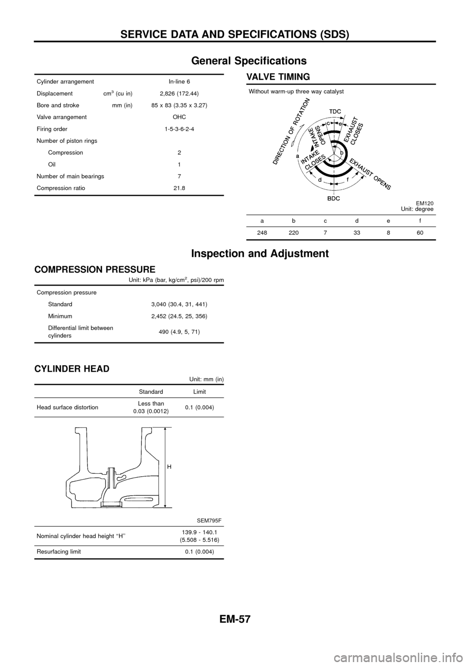
Without warm-up three way catalyst
EM120Unit: degree
abcde f
248 220 7 33 8 60
Inspection and Adjustment
COMPRESSION PRESSURE
Unit: kPa (bar, kg/cm2, psi)/200 rpm
Compression pressure
Standard 3,040 (30.4, 31, 441)
Minimum 2,452 (24.5, 25, 356)
Differential limit between
cylinders490 (4.9, 5, 71)
CYLINDER HEAD
Unit: mm (in)
Standard Limit
Head surface distortionLess than
0.03 (0.0012)0.1 (0.004)
SEM795F
Nominal cylinder head height ``H''139.9 - 140.1
(5.508 - 5.516)
Resurfacing limit 0.1 (0.004)
SERVICE DATA AND SPECIFICATIONS (SDS)
EM-57
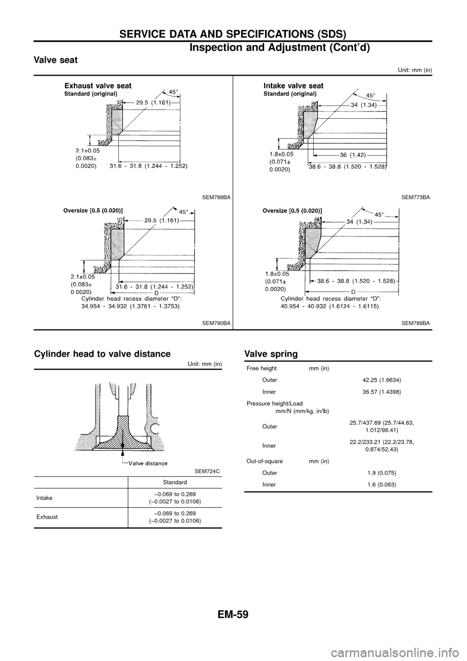
Valve seat
Unit: mm (in)
SEM788BASEM773BA
SEM790BASEM789BA
Cylinder head to valve distance
Unit: mm (in)
SEM724C
Standard
Intakeþ0.069 to 0.269
(þ0.0027 to 0.0106)
Exhaustþ0.069 to 0.269
(þ0.0027 to 0.0106)
Valve spring
Free height mm (in)
Outer 42.25 (1.6634)
Inner 36.57 (1.4398)
Pressure height/Load
mm/N (mm/kg, in/lb)
Outer25.7/437.69 (25.7/44.63,
1.012/98.41)
Inner22.2/233.21 (22.2/23.78,
0.874/52.43)
Out-of-square mm (in)
Outer 1.9 (0.075)
Inner 1.6 (0.063)
SERVICE DATA AND SPECIFICATIONS (SDS)
Inspection and Adjustment (Cont'd)
EM-59
Available shim
Thickness mm (in) Identi®cation mark
2.90 (0.1142) 2.90
2.85 (0.1122) 2.85
2.80 (0.1102) 2.80
2.75 (0.1083) 2.75
2.70 (0.1063) 2.70
2.65 (0.1043) 2.65
2.60 (0.1024) 2.60
2.55 (0.1004) 2.55
2.50 (0.0984) 2.50
2.45 (0.0965) 2.45
2.40 (0.0945) 2.40
2.35 (0.0925) 2.35
2.30 (0.0906) 2.30
2.25 (0.0886) 2.25
2.20 (0.0866) 2.20
Valve clearance
Unit: mm (in)
For adjusting
Hot Cold*
Intake0.28 - 0.38
(0.011 - 0.015)0.26 - 0.34
(0.010 - 0.013)
Exhaust0.32 - 0.42
(0.013 - 0.017)0.30 - 0.38
(0.012 - 0.015)
*: At a temperature of approximately 20ÉC (68ÉF)
Whenever valve clearances are adjusted to cold speci®cations,
check that the clearances satisfy hot speci®cations and adjust
again if necessary.
CAMSHAFT AND CAMSHAFT BEARING
Unit: mm (in)
Standard Limit
Camshaft journal to
bearing clearance0.045 - 0.086
(0.0018 - 0.0034)0.1 (0.004)
Inner diameter of cam-
shaft bearing30.000 - 30.021
(1.1811 - 1.1819)Ð
Outer diameter of cam-
shaft journal29.935 - 29.955
(1.1785 - 1.1793)Ð
Camshaft runout [TIR*] Ð 0.02 (0.0008)
Camshaft sprocket
runout [TIR*]Less than
0.25 (0.0098)Ð
Camshaft end play0.065 - 0.169
(0.0026 - 0.0067)0.20 (0.0079)
EM671
Cam height ``A''
Intake 48.005 - 48.195 (1.8900 - 1.8974)
Exhaust 49.505 - 49.695 (1.9490 - 1.9565)
Wear limit of cam height 0.15 (0.0059)
Valve lift
Intake 8.27 (0.326)
Exhaust 9.43 (0.371)
*: Total indicator reading
SEM797F
SERVICE DATA AND SPECIFICATIONS (SDS)
Inspection and Adjustment (Cont'd)
EM-60


