lock NISSAN PATROL 1998 Y61 / 5.G Engine Mechanical Workshop Manual
[x] Cancel search | Manufacturer: NISSAN, Model Year: 1998, Model line: PATROL, Model: NISSAN PATROL 1998 Y61 / 5.GPages: 65, PDF Size: 2.4 MB
Page 1 of 65
ENGINE MECHANICAL
SECTION
EM
CONTENTS
PRECAUTIONS...............................................................1
Parts Requiring Angular Tightening .............................1
Liquid Gasket Application Procedure ..........................1
PREPARATION................................................................2
NOISE, VIBRATION AND HARSHNESS (NVH)
TROUBLESHOOTING.....................................................6
NVH Troubleshooting Chart Ð Engine Noise .............7
OUTER COMPONENT PARTS.......................................8
COMPRESSION PRESSURE........................................10
Measurement of Compression Pressure ...................10
OIL PAN.........................................................................13
Removal .....................................................................13
Installation ..................................................................14
TIMING BELT.................................................................15
Removal .....................................................................15
Inspection...................................................................17
Installation ..................................................................18
OIL SEAL REPLACEMENT..........................................20
TURBOCHARGER.........................................................23
Removal and Installation ...........................................23
Inspection...................................................................24CHARGE AIR COOLERS..............................................27
CYLINDER HEAD..........................................................28
Removal .....................................................................29
Disassembly...............................................................30
Inspection...................................................................31
Assembly ...................................................................37
Installation ..................................................................37
VALVE CLEARANCE....................................................40
Checking ....................................................................40
Adjusting ....................................................................41
ENGINE REMOVAL.......................................................43
Removal .....................................................................44
Installation ..................................................................44
CYLINDER BLOCK.......................................................45
Disassembly...............................................................46
Inspection...................................................................46
Assembly ...................................................................53
SERVICE DATA AND SPECIFICATIONS (SDS)..........56
General Speci®cations ...............................................56
Inspection and Adjustment ........................................56
EM
Page 9 of 65
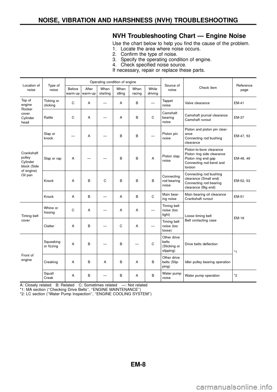
NVH Troubleshooting Chart Ð Engine Noise
Use the chart below to help you ®nd the cause of the problem.
1. Locate the area where noise occurs.
2. Con®rm the type of noise.
3. Specify the operating condition of engine.
4. Check speci®ed noise source.
If necessary, repair or replace these parts.
Location of
noiseType of
noiseOperating condition of engine
Source of
noiseCheck itemReference
page Before
warm-upAfter
warm-upWhen
startingWhen
idlingWhen
racingWhile
driving
To p o f
engine
Rocker
cover
Cylinder
headTicking or
clickingCAÐABÐTappet
noiseValve clearance EM-41
Rattle C A Ð A B CCamshaft
bearing
noiseCamshaft journal clearance
Camshaft runoutEM-37
Crankshaft
pulley
Cylinder
block (Side
of engine)
Oil panSlap or
knockÐAÐB BÐPiston pin
noisePiston and piston pin clear-
ance
Connecting rod bushing
clearanceEM-47, 53
Slap or rap A Ð Ð B B APiston slap
noisePiston-to-bore clearance
Piston ring side clearance
Piston ring end gap
Connecting rod bend and
torsionEM-48, 49
Knock A B C B B BConnecting
rod bearing
noiseConnecting rod bushing
clearance (Small end)
Connecting rod bearing
clearance (Big end)EM-52, 53
Knock A B Ð A B CMain bear-
ing noiseMain bearing oil clearance
Crankshaft runoutEM-51
Timing belt
coverWhine or
hissingCAÐAAÐTiming belt
noise (too
tight)
Loose timing belt
Belt contacting caseEM-18
Clatter A B Ð C A ÐTiming belt
noise (too
loose)
Front of
engineSqueaking
or ®zzingABÐBÐCOther drive
belts
(Sticking or
slipping)Drive belts de¯ection
*1
CreakingABABABOther drive
belts (Slip-
ping)Idler pulley bearing operation
Squall
CreakABÐBABWater pump
noiseWater pump operation *2
A: Closely related B: Related C: Sometimes related Ð: Not related
*1: MA section (``Checking Drive Belts'', ``ENGINE MAINTENANCE'')
*2: LC section (``Water Pump Inspection'', ``ENGINE COOLING SYSTEM'')
NOISE, VIBRATION AND HARSHNESS (NVH) TROUBLESHOOTING
EM-8
Page 18 of 65
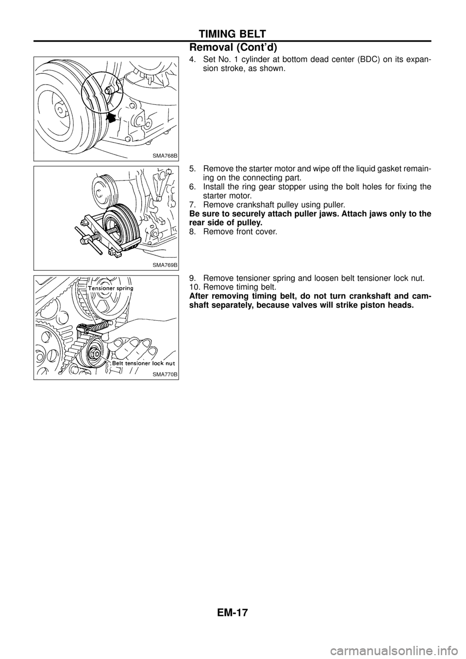
4. Set No. 1 cylinder at bottom dead center (BDC) on its expan-
sion stroke, as shown.
5. Remove the starter motor and wipe off the liquid gasket remain-
ing on the connecting part.
6. Install the ring gear stopper using the bolt holes for ®xing the
starter motor.
7. Remove crankshaft pulley using puller.
Be sure to securely attach puller jaws. Attach jaws only to the
rear side of pulley.
8. Remove front cover.
9. Remove tensioner spring and loosen belt tensioner lock nut.
10. Remove timing belt.
After removing timing belt, do not turn crankshaft and cam-
shaft separately, because valves will strike piston heads.
SMA768B
SMA769B
SMA770B
TIMING BELT
Removal (Cont'd)
EM-17
Page 21 of 65
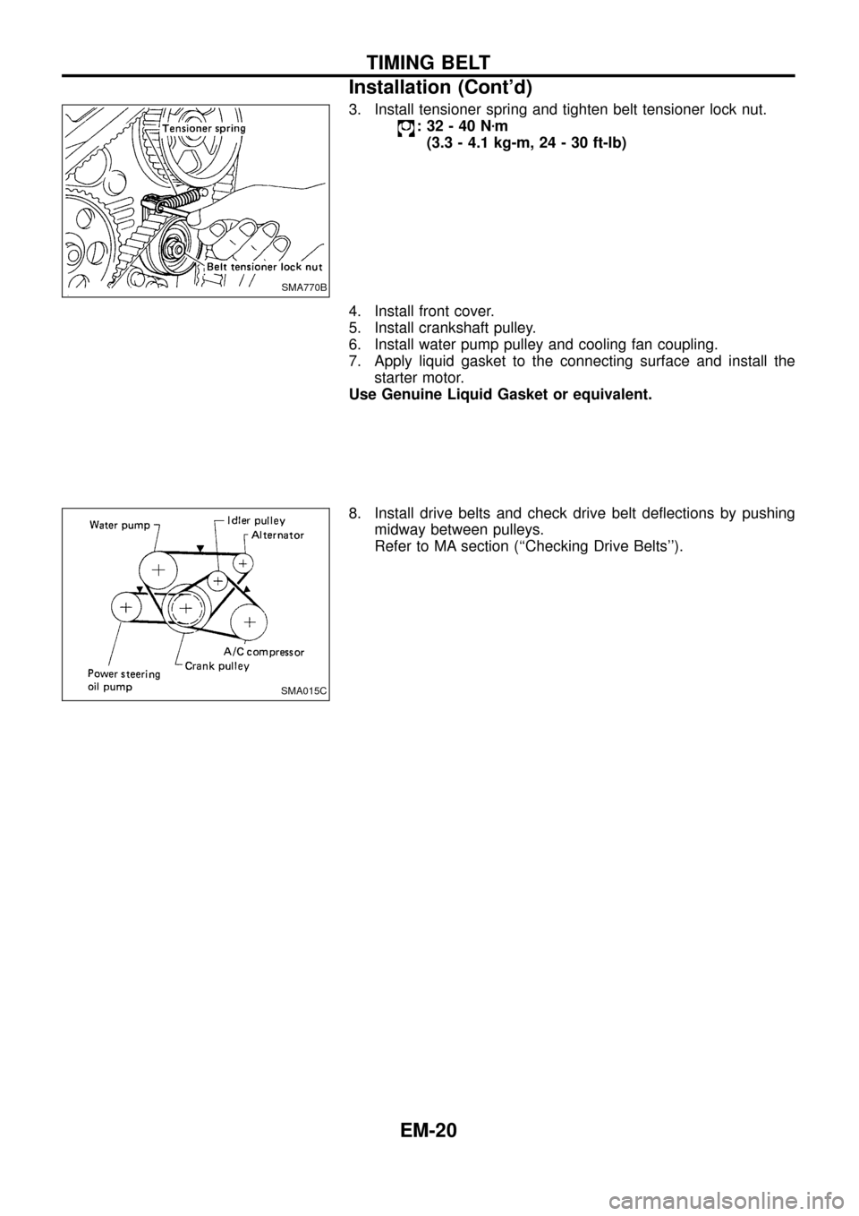
3. Install tensioner spring and tighten belt tensioner lock nut.
:32-40Nzm
(3.3 - 4.1 kg-m, 24 - 30 ft-lb)
4. Install front cover.
5. Install crankshaft pulley.
6. Install water pump pulley and cooling fan coupling.
7. Apply liquid gasket to the connecting surface and install the
starter motor.
Use Genuine Liquid Gasket or equivalent.
8. Install drive belts and check drive belt de¯ections by pushing
midway between pulleys.
Refer to MA section (``Checking Drive Belts'').
SMA770B
SMA015C
TIMING BELT
Installation (Cont'd)
EM-20
Page 24 of 65
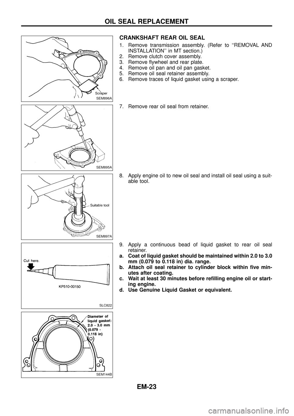
CRANKSHAFT REAR OIL SEAL
1. Remove transmission assembly. (Refer to ``REMOVAL AND
INSTALLATION'' in MT section.)
2. Remove clutch cover assembly.
3. Remove ¯ywheel and rear plate.
4. Remove oil pan and oil pan gasket.
5. Remove oil seal retainer assembly.
6. Remove traces of liquid gasket using a scraper.
7. Remove rear oil seal from retainer.
8. Apply engine oil to new oil seal and install oil seal using a suit-
able tool.
9. Apply a continuous bead of liquid gasket to rear oil seal
retainer.
a. Coat of liquid gasket should be maintained within 2.0 to 3.0
mm (0.079 to 0.118 in) dia. range.
b. Attach oil seal retainer to cylinder block within ®ve min-
utes after coating.
c. Wait at least 30 minutes before re®lling engine oil or start-
ing engine.
d. Use Genuine Liquid Gasket or equivalent.
SEM896A
SEM895A
SEM897A
SLC822
SEM144B
OIL SEAL REPLACEMENT
EM-23
Page 25 of 65
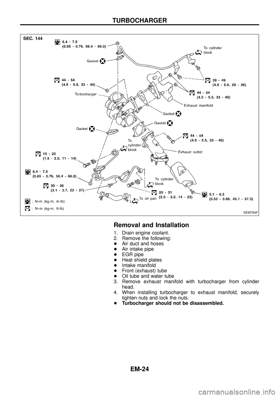
Removal and Installation
1. Drain engine coolant.
2. Remove the following:
+Air duct and hoses
+Air intake pipe
+EGR pipe
+Heat shield plates
+Intake manifold
+Front (exhaust) tube
+Oil tube and water tube
3. Remove exhaust manifold with turbocharger from cylinder
head.
4. When installing turbocharger to exhaust manifold, securely
tighten nuts and lock the nuts.
+Turbocharger should not be disassembled.
SEM784F
TURBOCHARGER
EM-24
Page 31 of 65
CAUTION:
+When installing sliding parts such as camshaft and oil
seal, be sure to apply new engine oil on their sliding sur-
faces.
+When tightening cylinder head bolts, apply new engine oil
to thread portions and seat surfaces of bolts.
Removal
1. Remove charge air cooler assembly.
2. Set No. 1 cylinder at BDC on its expansion stroke.
3. Drain engine coolant from drain plugs on cylinder block and
radiator.
4. Remove air cleaner and/or air duct.
5. Remove timing belt.
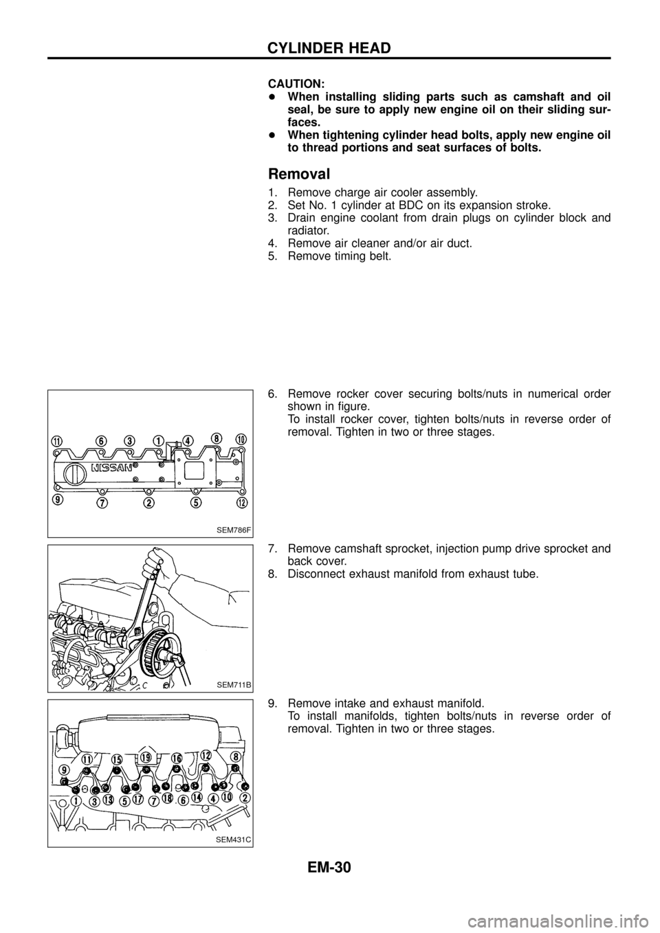
6. Remove rocker cover securing bolts/nuts in numerical order
shown in ®gure.
To install rocker cover, tighten bolts/nuts in reverse order of
removal. Tighten in two or three stages.
7. Remove camshaft sprocket, injection pump drive sprocket and
back cover.
8. Disconnect exhaust manifold from exhaust tube.
9. Remove intake and exhaust manifold.
To install manifolds, tighten bolts/nuts in reverse order of
removal. Tighten in two or three stages.
SEM786F
SEM711B
SEM431C
CYLINDER HEAD
EM-30
Page 33 of 65
Inspection
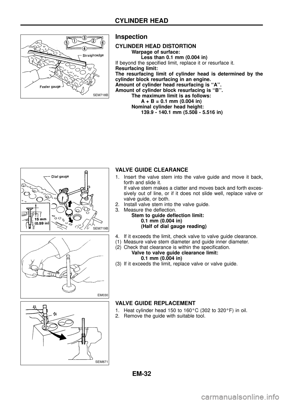
CYLINDER HEAD DISTORTION
Warpage of surface:
Less than 0.1 mm (0.004 in)
If beyond the speci®ed limit, replace it or resurface it.
Resurfacing limit:
The resurfacing limit of cylinder head is determined by the
cylinder block resurfacing in an engine.
Amount of cylinder head resurfacing is ``A''.
Amount of cylinder block resurfacing is ``B''.
The maximum limit is as follows:
A + B = 0.1 mm (0.004 in)
Nominal cylinder head height:
139.9 - 140.1 mm (5.508 - 5.516 in)
VALVE GUIDE CLEARANCE
1. Insert the valve stem into the valve guide and move it back,
forth and slide it.
If valve stem makes a clatter and moves back and forth exces-
sively out of line, or if it does not slide well, replace valve or
valve guide, or both.
2. Install valve stem into the valve guide.
3. Measure the de¯ection.
Stem to guide de¯ection limit:
0.1 mm (0.004 in)
(Half of dial gauge reading)
4. If it exceeds the limit, check valve to valve guide clearance.
(1) Measure valve stem diameter and guide inner diameter.
(2) Check that clearance is within the speci®cation.
Valve to valve guide clearance limit:
0.1 mm (0.004 in)
(3) If it exceeds the limit, replace valve or valve guide.
VALVE GUIDE REPLACEMENT
1. Heat cylinder head 150 to 160ÉC (302 to 320ÉF) in oil.
2. Remove the guide with suitable tool.
SEM718B
SEM719B
EM030
SEM871
CYLINDER HEAD
EM-32
Page 39 of 65
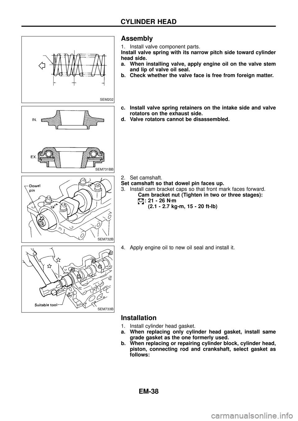
Assembly
1. Install valve component parts.
Install valve spring with its narrow pitch side toward cylinder
head side.
a. When installing valve, apply engine oil on the valve stem
and lip of valve oil seal.
b. Check whether the valve face is free from foreign matter.
c. Install valve spring retainers on the intake side and valve
rotators on the exhaust side.
d. Valve rotators cannot be disassembled.
2. Set camshaft.
Set camshaft so that dowel pin faces up.
3. Install cam bracket caps so that front mark faces forward.
Cam bracket nut (Tighten in two or three stages):
:21-26Nzm
(2.1 - 2.7 kg-m, 15 - 20 ft-lb)
4. Apply engine oil to new oil seal and install it.
Installation
1. Install cylinder head gasket.
a. When replacing only cylinder head gasket, install same
grade gasket as the one formerly used.
b. When replacing or repairing cylinder block, cylinder head,
piston, connecting rod and crankshaft, select gasket as
follows:
SEM202
SEM731BB
SEM732B
SEM733B
CYLINDER HEAD
EM-38
Page 40 of 65
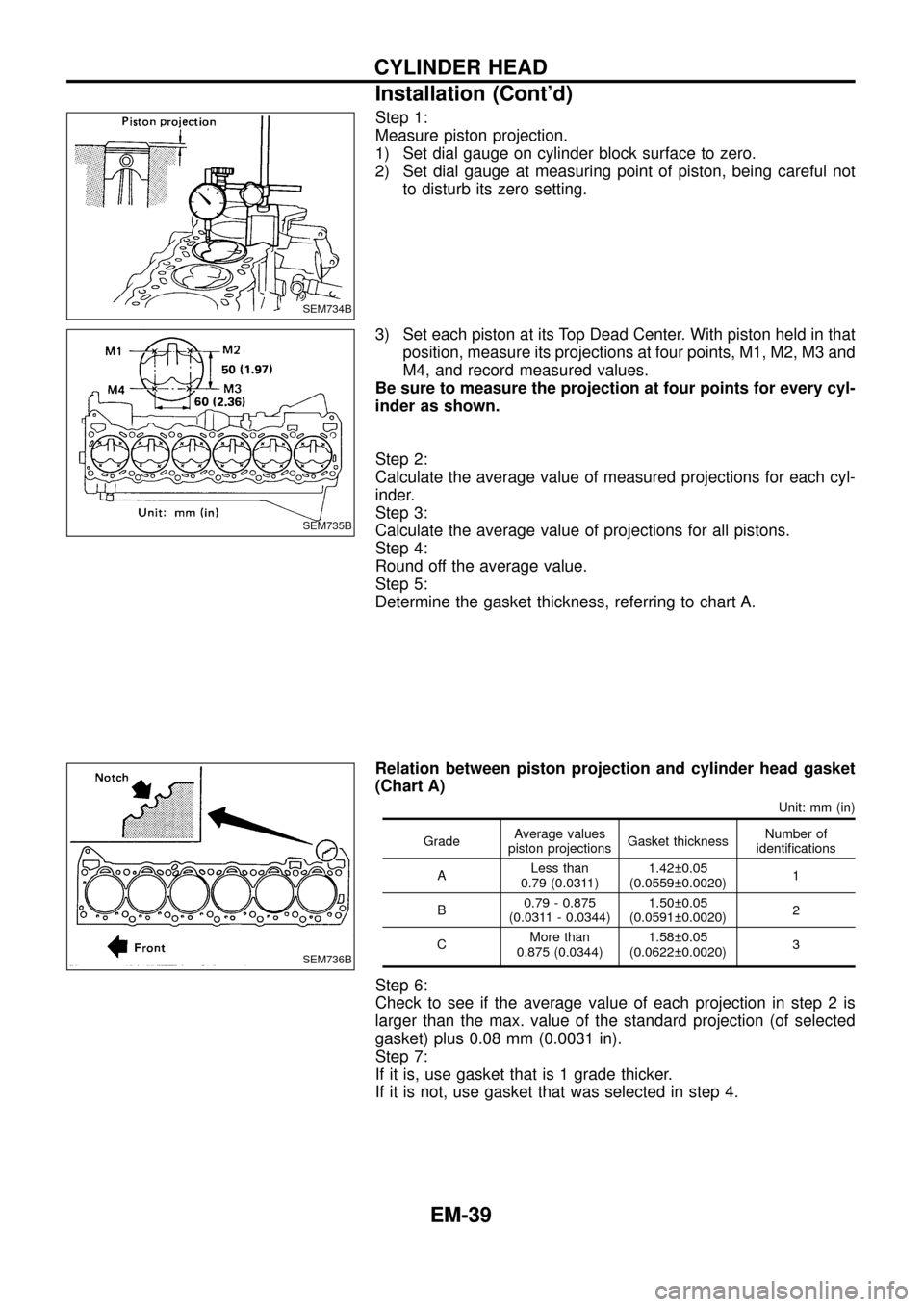
Step 1:
Measure piston projection.
1) Set dial gauge on cylinder block surface to zero.
2) Set dial gauge at measuring point of piston, being careful not
to disturb its zero setting.
3) Set each piston at its Top Dead Center. With piston held in that
position, measure its projections at four points, M1, M2, M3 and
M4, and record measured values.
Be sure to measure the projection at four points for every cyl-
inder as shown.
Step 2:
Calculate the average value of measured projections for each cyl-
inder.
Step 3:
Calculate the average value of projections for all pistons.
Step 4:
Round off the average value.
Step 5:
Determine the gasket thickness, referring to chart A.
Relation between piston projection and cylinder head gasket
(Chart A)
Unit: mm (in)
GradeAverage values
piston projectionsGasket thicknessNumber of
identi®cations
ALess than
0.79 (0.0311)1.42 0.05
(0.0559 0.0020)1
B0.79 - 0.875
(0.0311 - 0.0344)1.50 0.05
(0.0591 0.0020)2
CMore than
0.875 (0.0344)1.58 0.05
(0.0622 0.0020)3
Step 6:
Check to see if the average value of each projection in step 2 is
larger than the max. value of the standard projection (of selected
gasket) plus 0.08 mm (0.0031 in).
Step 7:
If it is, use gasket that is 1 grade thicker.
If it is not, use gasket that was selected in step 4.
SEM734B
SEM735B
SEM736B
CYLINDER HEAD
Installation (Cont'd)
EM-39