light RENAULT TWINGO 2009 2.G Panelwork Workshop Manual
[x] Cancel search | Manufacturer: RENAULT, Model Year: 2009, Model line: TWINGO, Model: RENAULT TWINGO 2009 2.GPages: 209
Page 4 of 209
Contents
Front wing upper mounting
support: Removal - Refi tting 42A-7
Front end panel: General
descr iption 42A-8
Front end panel: Removal -
Refitting 42A-9
Headlight carrier panel:
Removal - Refitting 42A-11
Front upper cross member:
General description 42A-12
Front upper cross member:
Removal - Refitting 42A-13
Scuttle side panel: General
descr iption 42A-14
Scuttle side panel:
Description 42A-16
Upper reinforcement of
scuttle side panel: General
descr iption 42A-18
Upper reinforcement of
scuttle side panel:
Description 42A-19
Front wheel arch: General
descr iption 42A-21
Front wheel arch: Description 42A-22
Front wheel arch, front
section: General description 42A-25
Dashboard cross member:
Removal - Refitting 42A-26
Windscreen aperture lower
cross member closure panel:
Description 42A-28
43A SIDE UPPER STRUCTURE
A-pillar : General description 43A-1
A-pillar : Description 43A-2
A-pillar reinforcement:
General description 43A-5 42A FRONT UPPER STRUCTUREA-pillar reinforcement:
Description 43A-6
Windscreen pillar lining:
General description 43A-8
B-pillar reinforcement:
General description 43A-9
B-pillar reinforcement:
Description 43A-10
Body side: General
descr iption 43A-12
Body side: Description 43A-13
Upper body: General
descr iption 43A-15
Upper body: Description 43A-17
44A REAR UPPER STRUCTURE
Rear wing panel: General
descr iption 44A-1
Rear wing panel: Description 44A-2
Rear lights mounting:
General description 44A-5
Rear lights mounting:
Description 44A-6
Outer rear wheel arch:
General description 44A-8
Outer rear wheel arch:
Description 44A-10
Inner rear wheel arch:
General description 44A-13
Inner rear wheel arch:
Description 44A-14
Quar ter panel lining: General
descr iption 44A-16
Quar ter panel lining:
Description 44A-17
Rear end panel assembly:
Description 44A-22 43A SIDE UPPER STRUCTURE
Page 10 of 209
40A-5
GENERAL INFORMATION
Vehicle on repair bench: Description
C44
40A
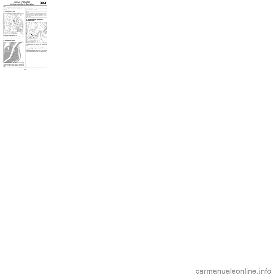
I - MAIN FRONT TRIM-SETTING REFERENCE
POINTS
1 - Front sub-frame in place
the jig covers the subframe bolt (A) .
Use this situation for a rear impact or a light frontal im-
pact without removing the mechanical components.
2 - Front sub-frame removed
The jig rests against the rear section of the side mem-
ber and is centred in the sub-frame rear mounting hole
(A) .Use this situation for a frontal impact with removal of
the mechanical components.
II - SECONDARY FRONT TRIM-SETTING
REFERENCE POINT
The jig covers the front subframe front mounting bolt
(C) .
Use this situation to confirm the trim-setting following a
rear impact, (e.g.: to replace a rear side member as-
sembly).
It is used to confirm the vehicle level in case of doubt
about the deformation of a main rear reference point.
120611
121747
Note:
If it is suspected that one of these points may be
deformed, use two additional points located in an
area not affected by the impact in order to confirm
trim-setting.
120610
Page 11 of 209
40A-6
GENERAL INFORMATION
Vehicle on repair bench: Description
C44
40A
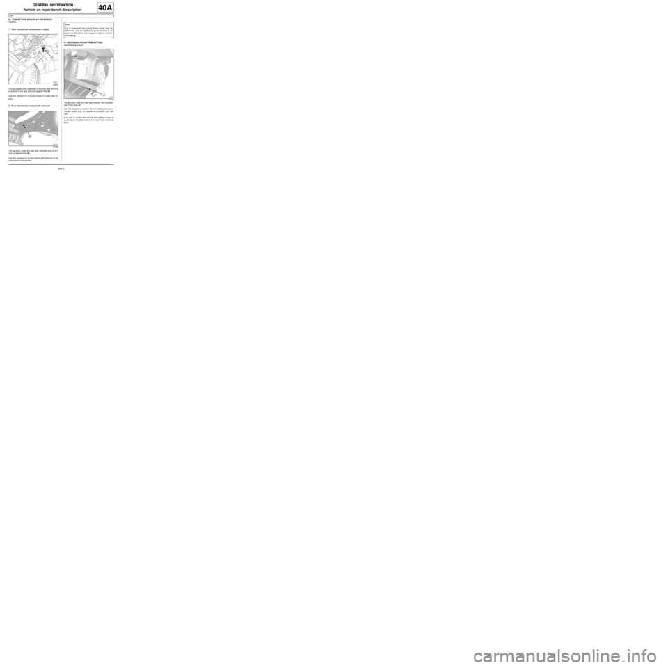
III - TRIM-SETTING MAIN REAR REFERENCE
POINTS
1 - Rear mechanical components in place
The jig supports the underside of the rear axle fork and
is centred in the rear axle bolt tapped hole (B) .
Use this situation for a frontal impact or a light rear im-
pact.
2 - Rear mechanical components removed
The jig rests under the rear side member and is cen-
tred on tapped hole (B) .
Use this situation for a rear impact with removal of the
mechanical components.IV - SECONDARY REAR TRIM-SETTING
REFERENCE POINT
The jig rests under the rear side member and is positio-
ned in the hole (J) .
Use this situation to confirm the trim-setting following a
frontal impact (e.g.: to replace a complete front half
unit).
It is used to confirm the vehicle trim setting in case of
doubt about the deformation of a main front reference
point.
120609
121746
Note:
If it is suspected that one of these points may be
deformed, use two additional points located in an
area not affected by the impact in order to confirm
trim-setting.
121748
Page 27 of 209
40A-22
GENERAL INFORMATION
Vehicle structure, rear section: Description
40A
(9) Rear light mounting (see 44A, Rear upper structure, Rear lights mounting:
Description, page 44A-6)
(10) Rear towing eye (see 41D, Rear lower structure, Rear towing eye: Des-
cription, page 41D-16)
(11) Quarter panel lining (see 44A, Rear upper structure, Quarter panel lining:
Description, page 44A-17)
(12) Rear end panel (see 44A, Rear upper structure, Rear end panel: Des-
cription, page 44A-25) No. Description Classification Type Thickness
(mm)
Page 28 of 209
40A-23
GENERAL INFORMATION
Vehicle structure, removable section: Description
40A
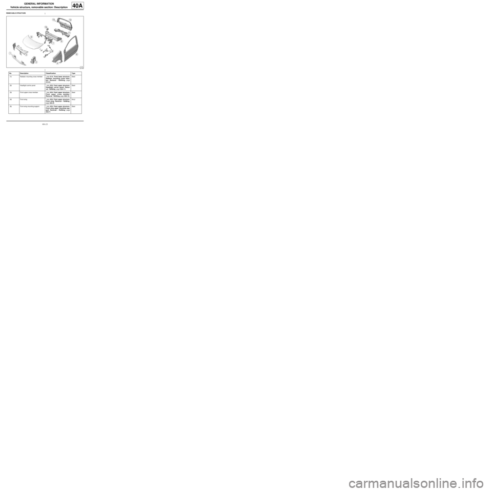
REMOVABLE STRUCTURE
121745
No. Description Classification Type
(1) Radiator mounting cross member (see 41A, Front lower structure,
Radiator mounting cross mem-
ber: Removal - Refitting, page
41A-5) Steel
(2) Headlight carrier panel (see 42A, Front upper structure,
Headlight carrier panel: Remo-
val - Refitting, page 42A-11) Steel
(3) Front upper cross member (see 42A, Front upper structure,
Front upper cross member:
Removal - Refitting, page 42A-13) Steel
(4) Front wing (see 42A, Front upper structure,
Front wing: Removal - Refitting,
page 42A-3) Noryl
(5) Front wing mounting support (see 42A, Front upper structure,
Front wing upper mounting sup-
port: Removal - Refitting, page
42A-7) Steel
Page 109 of 209
41D-18
REAR LOWER STRUCTURE
Rear impact lower cross member: Removal - Refitting41D
REMOVAL
I - REMOVAL PREPARATION OPERATION
aPosition the vehicle on a two-post lift (see Vehicle:
Towing and lifting) (MR 412, 02A, Lifting equip-
ment).
aRemove:
-the rear lights on the wing (see Rear wing light:
Removal - Refitting) (MR 411, 81A, Rear lighting),
-the rear bumper (see Rear bumper: Removal -
Refitting) (MR 412, 55A, Exterior protection).
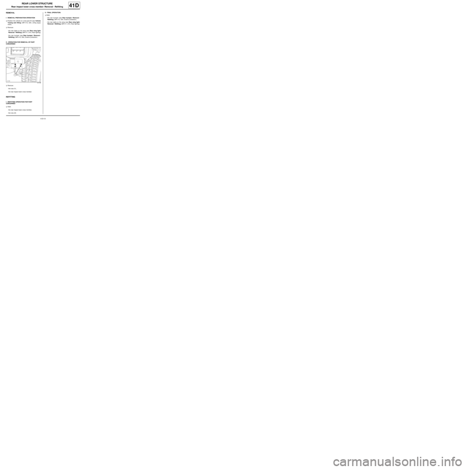
II - OPERATION FOR REMOVAL OF PART
CONCERNED
aRemove:
-the nuts (1) ,
-the rear impact lower cross member.
REFITTING
I - REFITTING OPERATION FOR PART
CONCERNED
aRefit:
-the rear impact lower cross member,
-the nuts (1) .II - FINAL OPERATION.
aRefit:
-the rear bumper (see Rear bumper: Removal -
Refitting) (MR 412, 55A, Exterior protection),
-the rear lights on the wing (see Rear wing light:
Removal - Refitting) (MR 411, 81A, Rear lighting).
121146
Page 110 of 209
42A-1
FRONT UPPER STRUCTURE
Front wing: General description
42A
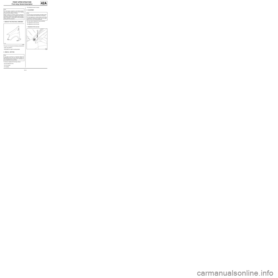
I - DESIGN OF THE STRUCTURAL COMPONENT
This type of front wing has the following characteristics:
-plastic wing (NORYL),
-wing bolted to its upper mounting bracket.
II - REMOVAL - REFITTING
To remove or replace the front wing, remove:
-the front wheel arch liner,
-the front bumper,
-the headlight,-the windscreen lower trim piece.
III - ADJUSTMENT
Two main areas of adjustment may be identified:
-the adjustment of the rear area,
-the adjustment of the front area
1 - Adjustment of the rear area: Note:
The information contained in the following descri-
bes the general repair procedure for all vehicles
having the same design for this part.
Before reading the following general information,
make sure that there are no special notes associa-
ted with the vehicle. These special notes are speci-
fied if necessary in other par ts of the sub-section
dealing with the component.
112606
Note:
In all cases of removal of a component without its
replacement with a new one, mark the position of
the mountings before removing the mountings to
avoid adjustments during refitting.
Note:
The front wing is the penultimate removable compo-
nent to be fitted to the vehicle body in the factory.
For final adjustment, correctly position all the other
components including the bumper and the headli-
ghts for them to be correctly positioned.
112042
Page 112 of 209
42A-3
FRONT UPPER STRUCTURE
Front wing: Removal - Refitting
42A
REMOVAL
I - REMOVAL PREPARATION OPERATION
aRemove:
-the front wheel arch liner (see Front wheel arch
liner: Removal - Refitting) (MR 412, 55A, Exterior
protection),
-the front bumper (see Front bumper: Removal -
Refitting) (MR 412, 55A, Exterior protection),
-the halogen headlight (see Halogen headlight:
Removal - Refitting) (MR 411, 80B, Headlights).
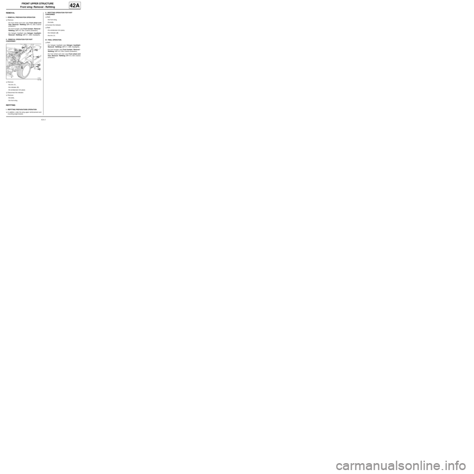
II - REMOVAL OPERATION FOR PART
CONCERNED
aRemove:
-the trim (1) ,
-the indicator (2) ,
-the windscreen trim piece.
aDisconnect the indicator.
aRemove:
-the bolts,
-the front wing.
REFITTING
I - REFITTING PREPARATIONS OPERATION
aIn addition, order the wing upper reinforcement and
mounting angle bracket.II - REFITTING OPERATION FOR PART
CONCERNED
aRefit:
-the front wing,
-the bolts.
aConnect the indicator.
aRefit:
-the windscreen trim piece,
-the indicator (2) ,
-the trim (1) .
III - FINAL OPERATION.
aRefit:
-the halogen headlight (see Halogen headlight:
Removal - Refitting) (MR 411, 80B, Headlights),
-the front bumper (see Front bumper: Removal -
Refitting) (MR 412, 55A, Exterior protection),
-the front wheel arch liner (see Front wheel arch
liner: Removal - Refitting) (MR 412, 55A, Exterior
protection).
121198
Page 114 of 209
42A-5
FRONT UPPER STRUCTURE
Front wing: Adjustment
42A
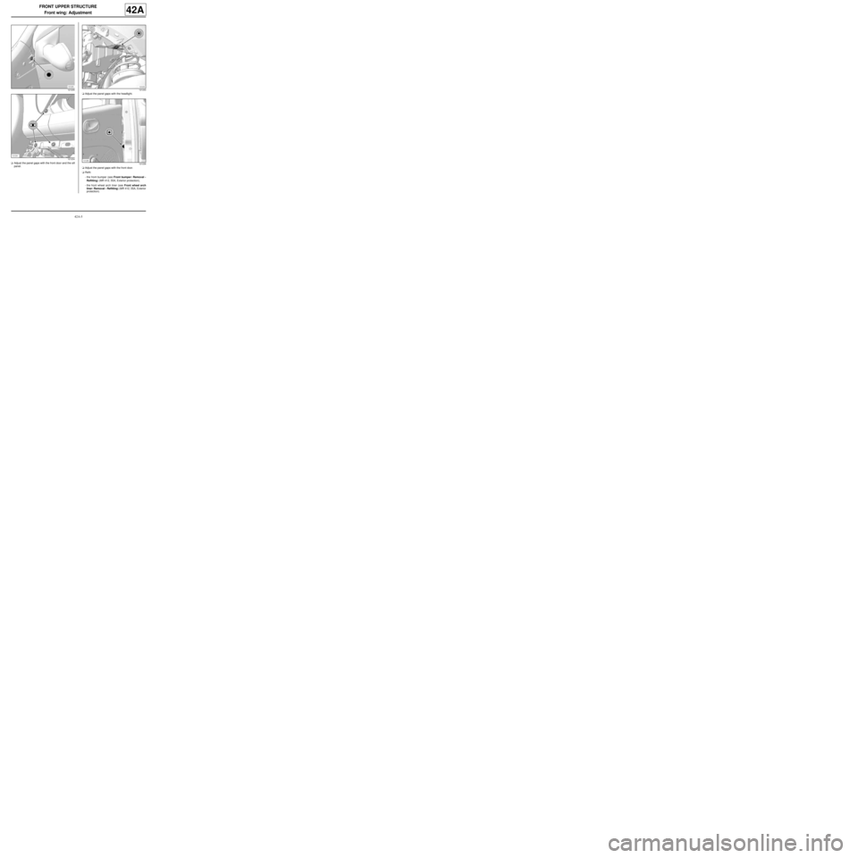
aAdjust the panel gaps with the front door and the sill
panel.aAdjust the panel gaps with the headlight.
aAdjust the panel gaps with the front door.
aRefit:
-the front bumper (see Front bumper: Removal -
Refitting) (MR 412, 55A, Exterior protection),
-the front wheel arch liner (see Front wheel arch
liner: Removal - Refitting) (MR 412, 55A, Exterior
protection).
121235
121234121233
121236
Page 116 of 209
42A-7
FRONT UPPER STRUCTURE
Front wing upper mounting support: Removal - Refitting42A
REMOVAL
I - REMOVAL PREPARATION OPERATION
aRemove:
-the front wheel arch liner (see Front wheel arch
liner: Removal - Refitting) (MR 412, 55A, Exterior
protection),
-the front bumper (see Front bumper: Removal -
Refitting) (MR 412, 55A, Exterior protection),
-the halogen headlight (see Halogen headlight:
Removal - Refitting) (MR 411, 80B, Headlights),
-the front wing (see 42A, Front upper structure,
Front wing: Removal - Refitting, page 42A-3) .
II - OPERATION FOR REMOVAL OF PART
CONCERNED
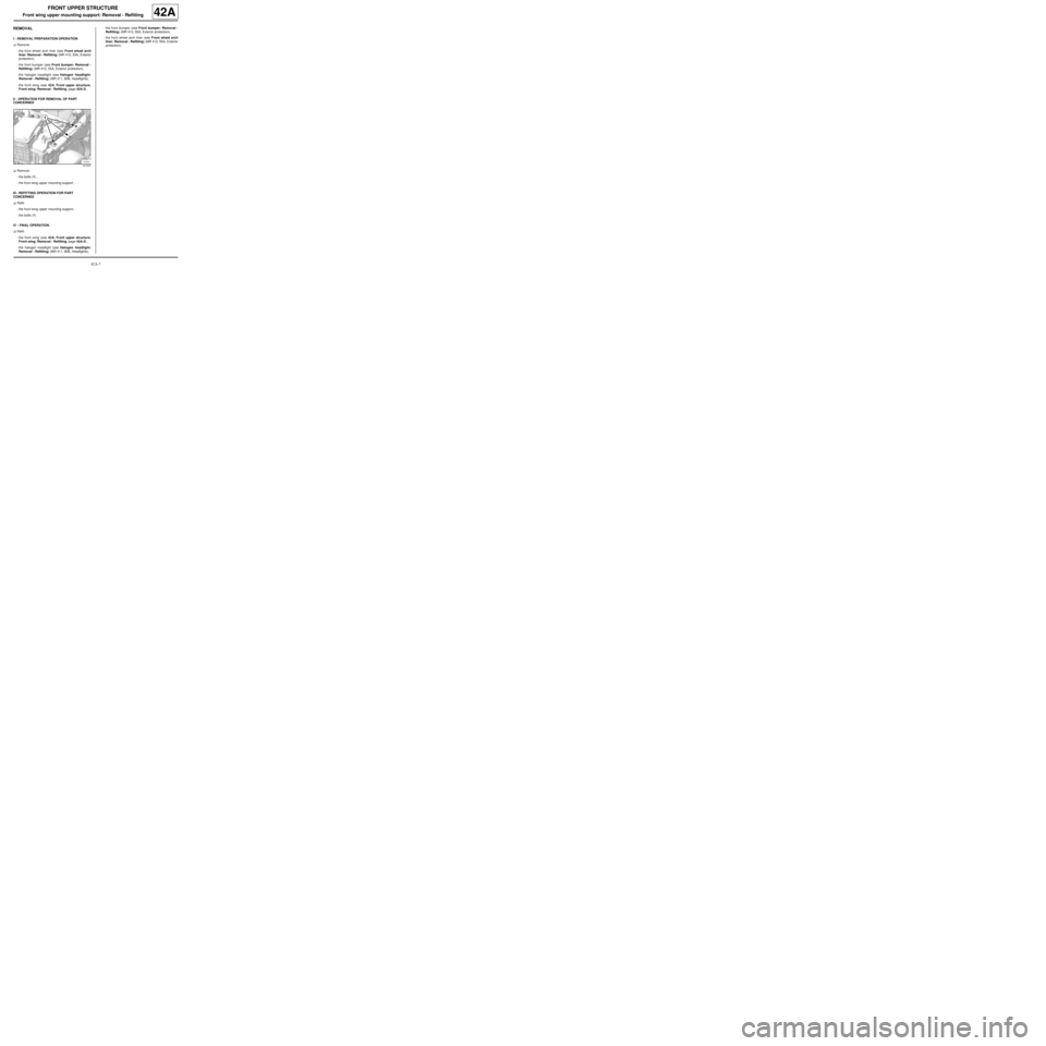
aRemove:
-the bolts (1) ,
-the front wing upper mounting support ,
III - REFITTING OPERATION FOR PART
CONCERNED
aRefit:
-the front wing upper mounting support,
-the bolts (1) .
IV - FINAL OPERATION.
aRefit:
-the front wing (see 42A, Front upper structure,
Front wing: Removal - Refitting, page 42A-3) ,
-the halogen headlight (see Halogen headlight:
Removal - Refitting) (MR 411, 80B, Headlights),-the front bumper (see Front bumper: Removal -
Refitting) (MR 412, 55A, Exterior protection),
-the front wheel arch liner (see Front wheel arch
liner: Removal - Refitting) (MR 412, 55A, Exterior
protection).
121237