wheel RENAULT TWINGO 2009 2.G Panelwork Workshop Manual
[x] Cancel search | Manufacturer: RENAULT, Model Year: 2009, Model line: TWINGO, Model: RENAULT TWINGO 2009 2.GPages: 209
Page 4 of 209
Contents
Front wing upper mounting
support: Removal - Refi tting 42A-7
Front end panel: General
descr iption 42A-8
Front end panel: Removal -
Refitting 42A-9
Headlight carrier panel:
Removal - Refitting 42A-11
Front upper cross member:
General description 42A-12
Front upper cross member:
Removal - Refitting 42A-13
Scuttle side panel: General
descr iption 42A-14
Scuttle side panel:
Description 42A-16
Upper reinforcement of
scuttle side panel: General
descr iption 42A-18
Upper reinforcement of
scuttle side panel:
Description 42A-19
Front wheel arch: General
descr iption 42A-21
Front wheel arch: Description 42A-22
Front wheel arch, front
section: General description 42A-25
Dashboard cross member:
Removal - Refitting 42A-26
Windscreen aperture lower
cross member closure panel:
Description 42A-28
43A SIDE UPPER STRUCTURE
A-pillar : General description 43A-1
A-pillar : Description 43A-2
A-pillar reinforcement:
General description 43A-5 42A FRONT UPPER STRUCTUREA-pillar reinforcement:
Description 43A-6
Windscreen pillar lining:
General description 43A-8
B-pillar reinforcement:
General description 43A-9
B-pillar reinforcement:
Description 43A-10
Body side: General
descr iption 43A-12
Body side: Description 43A-13
Upper body: General
descr iption 43A-15
Upper body: Description 43A-17
44A REAR UPPER STRUCTURE
Rear wing panel: General
descr iption 44A-1
Rear wing panel: Description 44A-2
Rear lights mounting:
General description 44A-5
Rear lights mounting:
Description 44A-6
Outer rear wheel arch:
General description 44A-8
Outer rear wheel arch:
Description 44A-10
Inner rear wheel arch:
General description 44A-13
Inner rear wheel arch:
Description 44A-14
Quar ter panel lining: General
descr iption 44A-16
Quar ter panel lining:
Description 44A-17
Rear end panel assembly:
Description 44A-22 43A SIDE UPPER STRUCTURE
Page 21 of 209

40A-16
GENERAL INFORMATION
Vehicle structure, front section: Description
40A
(9) Engine stand (see 41A, Front lower structure, Engine stand: Descrip-
tion, page 41A-21)
(10) Front left-hand wheel arch (see 42A, Front upper structure, Front wheel arch: Des-
cription, page 42A-22)
(11) Front half unit (see 41A, Front lower structure, Front half unit: Des-
cription, page 41A-24)
(12) Front right-hand wheel arch (see 42A, Front upper structure, Front wheel arch: Des-
cription, page 42A-22)
(13) Front wheel arch, front section (see 42A, Front upper structure, Front wheel arch: Des-
cription, page 42A-22) No. Description Classification Type Thickness
(mm)
Page 26 of 209

40A-21
GENERAL INFORMATION
Vehicle structure, rear section: Description
40A
REAR STRUCTURE
120917
No. Description Classification Type Thickness
(mm)
(1) Quarter panel rear upper stiffener (see MR 400)HLE1
(2) Rear end panel lining (see 44A, Rear upper structure,
Rear end panel assembly: Des-
cription, page 44A-22) Mild
steel0.95
(3) Rear wing panel (see 44A, Rear upper structure, Rear wing panel: Des-
cription, page 44A-2)
(4) Outer rear wheel arch (see 44A, Rear upper structure, Outer rear wheel arch:
Description, page 44A-10)
(5) Rear side member (see 41D, Rear lower structure, Rear side member:
Description, page 41D-8)
(6) Rear side member assembly (see 41D, Rear lower structure, Rear side member
assembly: Description, page 41D-5)
(7) Rear floor (see 41D, Rear lower structure, Rear floor: Description,
page 41D-1)
(8) Inner wheel arch (see 44A, Rear upper structure, Inner rear wheel arch:
Description, page 44A-14)
Page 30 of 209

40A-25
GENERAL INFORMATION
Structural components to be positioned on the repair bench: Description40A
I - PARTS REQUIRING THE USE OF A BODY JIG
BENCH
(1) Front wheel arch
(2) Front half-unit
(3) Engine mounting
(4) Subframe left-hand front mounting
(5) Front side member front section
(6) Rear side member rear section
(7) Rear side member
(8) Rear side member assembly
(9) Rear floor centre cross member
(10) Inner rear wheel archII - FRONT SUBFRAME REAR MOUNTING
121751
121747
Page 32 of 209
40A-27
GENERAL INFORMATION
Structural components to be positioned on the repair bench: Description40A
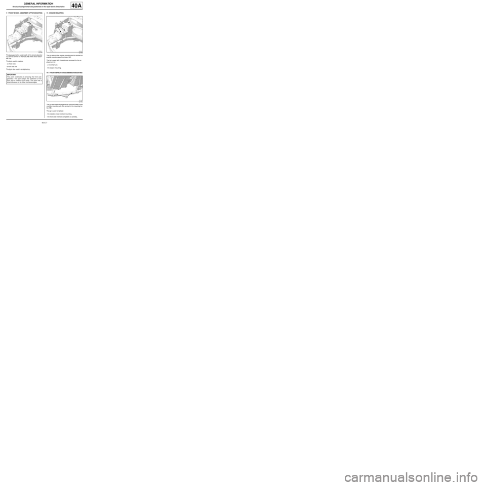
V - FRONT SHOCK ABSORBER UPPER MOUNTING
The jig supports the underneath of the shock absorber
cup and is centred on the hole (14) of the shock absor-
ber cup.
The jig is used to replace:
-a wheel arch,
-a front half unit.
The jig is also used in straightening.VI - ENGINE MOUNTING
The jig rests on the engine mounting and is centred on
engine mounting securing holes (15) .
The jig is used with the subframe removed for the re-
placement of:
-a front half unit.
-the engine mounting.
VII - FRONT IMPACT CROSS MEMBER MOUNTING
The jig rests vertically against the front end lower cross
member mounting unit, it is centred in the mounting ho-
les (16) .
The jig is used to replace:
-the radiator cross member mounting,
-the front side member completely or partially,.
121753
IMPORTANT
This point contributes to ensuring the front axle
geometry. This point aligns the subframe of the
front axle in relation to the body. This point has a
direct influence on all of the front axle angles.
121753
121754
Page 33 of 209
40A-28
GENERAL INFORMATION
Structural components to be positioned on the repair bench: Description40A
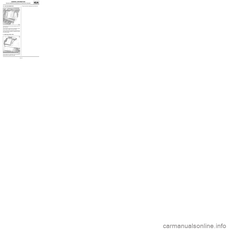
VIII - REAR SIDE MEMBER END
The jig rests under the rear side member and is cen-
tred in hole (17) .
The jig should be used with the mechanical compo-
nents in place to realign a rear side member.
The jig is used with the mechanical components remo-
ved, under the same conditions, to replace the comple-
te rear side member.
IX - INNER REAR WHEEL ARCH
The jig supports the underneath of the rear shock ab-
sorber cup and is centred on hole (18) .The jig is used when replacing the rear wheel arch.
121748
121749
Page 62 of 209

41A-23
FRONT LOWER STRUCTURE
Front half unit: General description
41A
DESIGN OF THE STRUCTURAL COMPONENT
The special feature of this type of part is that it combi-
nes the functions of front side member, front wheel
arch, centre floor front side cross member and front
end side cross member, and is made up of several pa-
nels of different types and thicknesses.IMPORTANT
Use a repair bench to ensure the positioning of the
points and the geometr y of the axle assemblies.
Note:
The information contained in the following descri-
bes the general repair procedure for all vehicles
having the same design for this part.
Before reading the following general information,
make sure that there are no special notes associa-
ted with the vehicle. These special notes are speci-
fied if necessary in other par ts of the sub-section
dealing with the component.
Note:
For a detailed description of a particular connec-
tion, see MR 400.
109546
Page 63 of 209

41A-24
FRONT LOWER STRUCTURE
Front half unit: Description
C44
41A
Right-hand side
There is only one way of replacing this part:
-complete replacement.
I - COMPOSITION OF THE SPARE PART
Left sideRight-hand side
125411
IMPORTANT
Use a repair bench to ensure the positioning of the
points and the geometr y of the axle assemblies.
120631
No. Description Type Thic-
kness
(mm)
(1) Front side mem-
ber closure panelHEL1.4
(2) S ide member,
front sectionHEL1.5
(3) Wheel arch Mild
steel1.2
(4) Cup height adjus-
terMild
steel1.3
120630
No. Description Type Thic-
kness
(mm)
(5) S ide member,
front sectionHEL/
Mild
steel1.5
(6) Front side mem-
ber closure panelHEL1.4
(7) Wheel arch Mild
steel1.2
Page 93 of 209
41D-2
REAR LOWER STRUCTURE
Rear floor: Description
41D
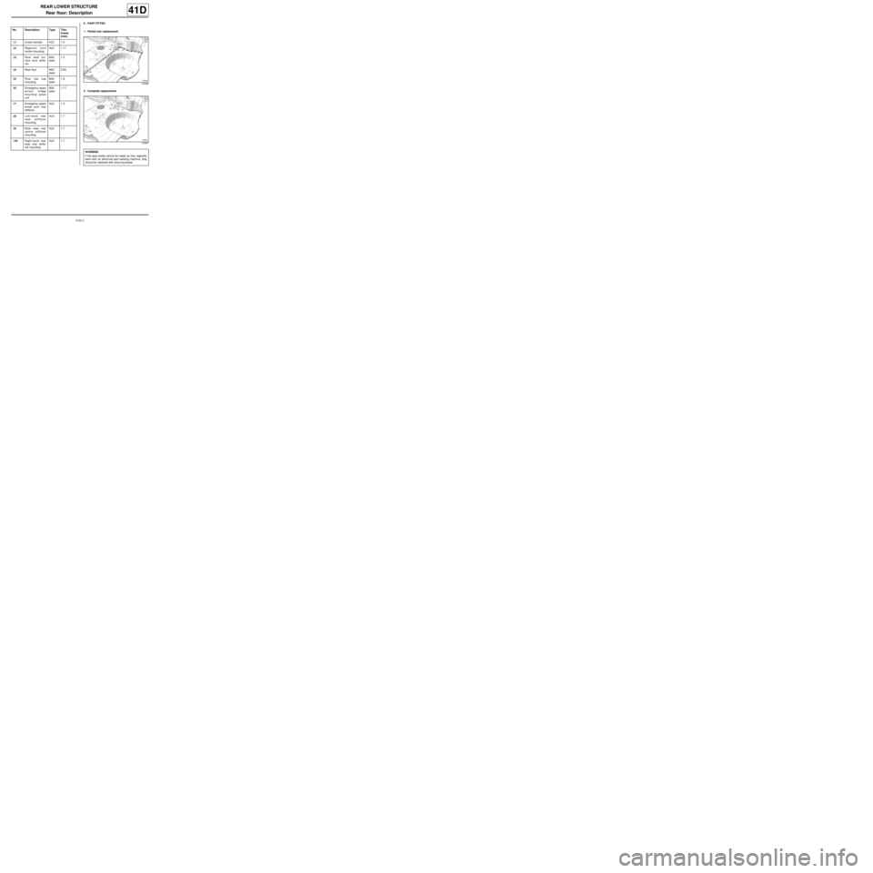
II - PART FITTED
1 - Partial rear replacement
2 - Complete replacement No. Description Type Thic-
kness
(mm)
(1) Cross member HLE 1.5
(2) Reservoir front
centre mountingHLE 1.17
(3) Rear seat run-
ners front stiffe-
nerMild
steel1.2
(4) Rear floor Mild
steel0.65
(5) Rear tow eye
mountingMild
steel1.8
(6) Emergency spare
wheel bridge
mounting piece
unitMild
steel1.17
(7) Emergency spare
wheel arch rear
stiffenerHLE 1.5
(8) Left-hand rear
seat stiffener
mountingHLE 1.7
(9) Rear seat rear
centre stiffener
mountingHLE 1.7
(10) Right-hand rear
seat rear stiffe-
ner mountingHLE 1.7
120988
120987
WARNING
If the spot welds cannot be made as they originally
were with an electrical spot welding machine, they
should be replaced with securing beads.
Page 110 of 209
42A-1
FRONT UPPER STRUCTURE
Front wing: General description
42A
I - DESIGN OF THE STRUCTURAL COMPONENT
This type of front wing has the following characteristics:
-plastic wing (NORYL),
-wing bolted to its upper mounting bracket.
II - REMOVAL - REFITTING
To remove or replace the front wing, remove:
-the front wheel arch liner,
-the front bumper,
-the headlight,-the windscreen lower trim piece.
III - ADJUSTMENT
Two main areas of adjustment may be identified:
-the adjustment of the rear area,
-the adjustment of the front area
1 - Adjustment of the rear area: Note:
The information contained in the following descri-
bes the general repair procedure for all vehicles
having the same design for this part.
Before reading the following general information,
make sure that there are no special notes associa-
ted with the vehicle. These special notes are speci-
fied if necessary in other par ts of the sub-section
dealing with the component.
112606
Note:
In all cases of removal of a component without its
replacement with a new one, mark the position of
the mountings before removing the mountings to
avoid adjustments during refitting.
Note:
The front wing is the penultimate removable compo-
nent to be fitted to the vehicle body in the factory.
For final adjustment, correctly position all the other
components including the bumper and the headli-
ghts for them to be correctly positioned.
112042