Acc TOYOTA PRIUS PRIME 2023 Owner's Manual
[x] Cancel search | Manufacturer: TOYOTA, Model Year: 2023, Model line: PRIUS PRIME, Model: TOYOTA PRIUS PRIME 2023Pages: 680, PDF Size: 14.97 MB
Page 55 of 680

551-2. Child safety
1
For safety and security
A child restraint system for a
small child or baby must itself be
properly restrained on the seat
with the lap portion of the
lap/shoulder belt.
■Installing child restraint
system using a seat belt
(child restraint lock func-
tion belt)
Install the child restraint system
in accordance to the operation
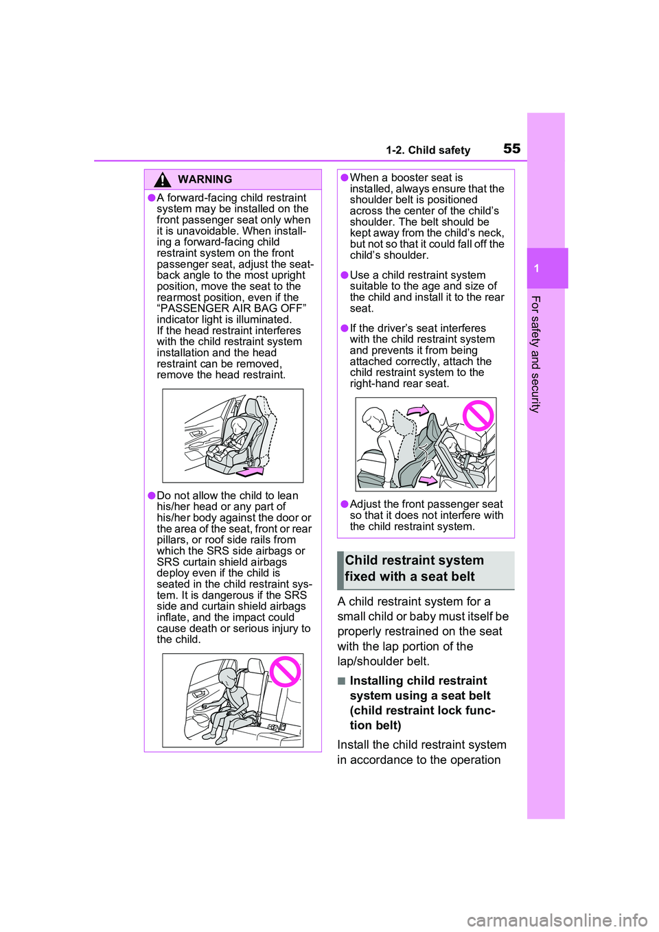
WARNING
●A forward-facing child restraint
system may be installed on the
front passenger seat only when
it is unavoidable. When install-
ing a forward-facing child
restraint system on the front
passenger seat, adjust the seat-
back angle to the most upright
position, move the seat to the
rearmost position, even if the
“PASSENGER AIR BAG OFF”
indicator light is illuminated.
If the head restraint interferes
with the child restraint system
installation and the head
restraint can be removed,
remove the head restraint.
●Do not allow the child to lean
his/her head or any part of
his/her body against the door or
the area of the seat, front or rear
pillars, or roof side rails from
which the SRS side airbags or
SRS curtain shield airbags
deploy even if the child is
seated in the child restraint sys-
tem. It is dangerous if the SRS
side and curtain shield airbags
inflate, and the impact could
cause death or serious injury to
the child.
●When a booster seat is
installed, always ensure that the
shoulder belt is positioned
across the center of the child’s
shoulder. The belt should be
kept away from the child’s neck,
but not so that it could fall off the
child’s shoulder.
●Use a child restraint system
suitable to the age and size of
the child and install it to the rear
seat.
●If the driver’s seat interferes
with the child restraint system
and prevents it from being
attached correctly, attach the
child restraint system to the
right-hand rear seat.
●Adjust the front passenger seat
so that it does not interfere with
the child restraint system.
Child restraint system
fixed with a seat belt
Page 58 of 680

581-2. Child safety
check that it cannot be extended.
7If the child restraint has a top
tether strap, follow the child
restraint manufacturer’s
operation manual regarding
the installation, using the top
tether strap to latch onto the
top tether strap anchor.
( P.62)
8 After installing the child
restraint system, rock it back
and forth to ensure that it is
installed securely. ( P.59)
■Booster seat
1 If installing the child restraint
system to the front passen-
ger seat is unavoidable, refer
to P.54for front passenger
seat adjustment.
2 High back type: If the head
restraint interferes with your
child restraint system, and
the head restraint can be removed, remove the head
restraint. (
P.212)
3 Place the child restraint sys-
tem on the seat facing the
front of the vehicle.
Booster type
High back type
4 Sit the child in the child
restraint system. Fit the seat
belt to the child restraint sys-
tem according to the manu-
facturer’s instructions and
insert the plate into the
Page 60 of 680

601-2. Child safety
■Child restraint LATCH
anchors
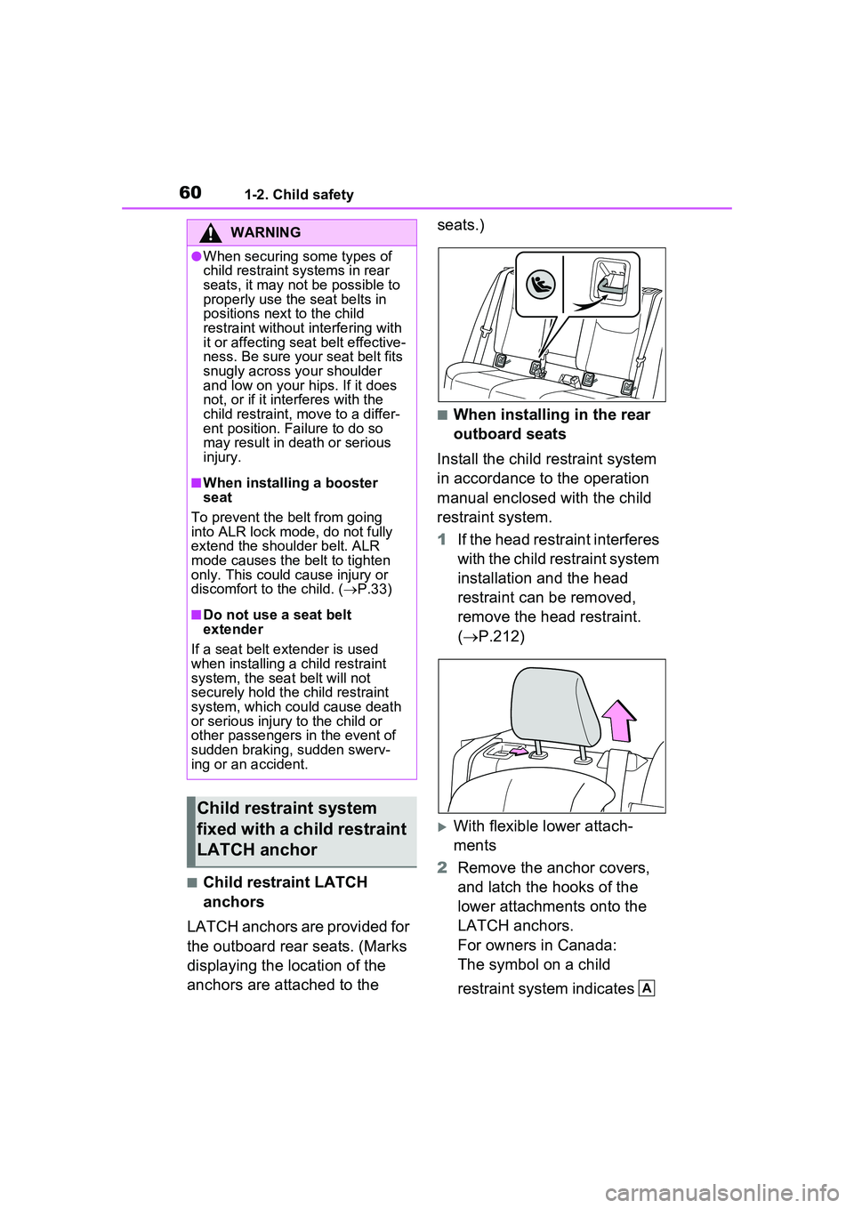
LATCH anchors are provided for
the outboard rear seats. (Marks
displaying the location of the
anchors are attached to the seats.)
■When installing in the rear
outboard seats
Install the child restraint system
in accordance to the operation
manual enclosed with the child
restraint system.
1 If the head restraint interferes
with the child restraint system
installation and the head
restraint can be removed,
remove the head restraint.
( P.212)
With flexible lower attach-
ments
2 Remove the anchor covers,
and latch the hooks of the
lower attachments onto the
LATCH anchors.
For owners in Canada:
The symbol on a child
restraint system indicates
WARNING
●When securing some types of
child restraint systems in rear
seats, it may not be possible to
properly use the seat belts in
positions next to the child
restraint without interfering with
it or affecting se at belt effective-
ness. Be sure your seat belt fits
snugly across your shoulder
and low on your hips. If it does
not, or if it interferes with the
child restraint, mo ve to a differ-
ent position. Failure to do so
may result in death or serious
injury.
■When installing a booster
seat
To prevent the belt from going
into ALR lock mode, do not fully
extend the shoulder belt. ALR
mode causes the belt to tighten
only. This could cause injury or
discomfort to the child. ( P.33)
■Do not use a seat belt
extender
If a seat belt extender is used
when installing a child restraint
system, the seat belt will not
securely hold th e child restraint
system, which could cause death
or serious injury to the child or
other passengers in the event of
sudden braking, sudden swerv-
ing or an accident.
Child restraint system
fixed with a child restraint
LATCH anchor
A
Page 63 of 680

631-2. Child safety
1
For safety and security
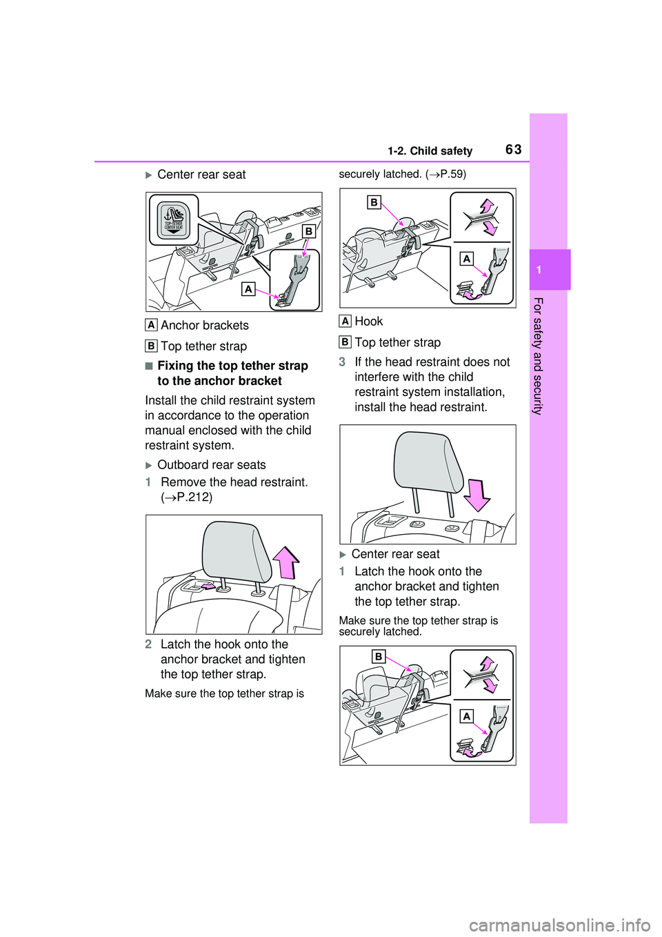
Center rear seatAnchor brackets
Top tether strap
■Fixing the top tether strap
to the anchor bracket
Install the child restraint system
in accordance to the operation
manual enclosed with the child
restraint system.
Outboard rear seats
1 Remove the head restraint.
( P.212)
2 Latch the hook onto the
anchor bracket and tighten
the top tether strap.
Make sure the top tether strap is securely latched. (
P.59)
Hook
Top tether strap
3 If the head restraint does not
interfere with the child
restraint system installation,
install the head restraint.
Center rear seat
1 Latch the hook onto the
anchor bracket and tighten
the top tether strap.
Make sure the top tether strap is
securely latched.
A
B
A
B
Page 67 of 680

671-3. Emergency assistance
1
For safety and security
The following indicator light pat-
terns indicate specific system
usage conditions:
Green indicator light on =
Active service
Green indicator light flashing
= Safety Connect call in pro-
cess
Red indicator light (except at
vehicle start-up) = System
malfunction (contact your
Toyota dealer)
No indicator light (off) =
Safety Connect service not
active
■Automatic Collision Notifi-
cation
In case of either airbag deploy-
ment or severe rear-end colli-
sion, the system is designed to
automatically call the response
center. The responding agent
receives the vehicle’s location
and attempts to speak with the
vehicle occupants to assess the
level of emergency. If the occu-
pants are unable to communi-
cate, the agent automatically
treats the call as an emergency,
contacts the nearest emer-
gency services provider to
describe the situation, and
requests that assistance be sent
to the location.
■Stolen Vehicle Location
If your vehicle is stolen, Safety
Connect can work with local
authorities to assist them in
locating and recovering the
vehicle. After filing a police
report, call the Customer Experi-
ence Center at 1-800-331-4331
in the United States, 1-877-855-
8377 in Puerto Rico or 1-888-
869-6828 in Canada, and follow
the prompts for Safety Connect
to initiate this service.
In addition to assisting law
enforcement with recovery of a
stolen vehicle, Safety-Connect-
equipped vehicle location data
may, under certain circum-
stances, be shared with third
parties to locate your vehicle.
Further information is available
at Toyota.com in the United
States, Toyotapr.com in Puerto
Rico and Toyota.ca in Canada.
■Emergency Assistance But-
ton (“SOS”)
In the event of an emergency on
the road, push the “SOS” button
to reach the Safety Connect
response center. The answering
agent will determine your vehi-
cle’s location, assess the emer-
gency, and dispatch the
necessary assistance required.
If you accidentally press the “SOS”
button, tell the response-center
agent that you are not experiencing
an emergency.
Safety Connect services
Page 70 of 680

701-4. Theft deterrent system
1-4.Theft deterrent system
The indicator light flashes after
the power switch has been
turned to off to indicate that the
system is operating.
The indicator light stops flashing
after the power switch has been
turned to ACC or ON to indicate
that the system has been can-
celed.
■System maintenance
The vehicle has a maintenance-free
type immobilizer system.
■Conditions that may cause the
system to malfunction
●If the grip portion of the key is in
contact with a metallic object
●If the key is in close proximity to or
touching a key to the security sys-
tem (key with a built-in transpon-
der chip) of another vehicle
Immobilizer system
The vehicle’s keys have
built-in transponder chips
that prevent the hybrid sys-
tem from starting if a key
has not been previously
registered in the vehicle’s
on-board computer.
Never leave the keys inside
the vehicle when you leave
the vehicle.
This system is designed to
help prevent vehicle theft but
does not guarantee absolute
security against all vehicle
thefts.
Operating the system
NOTICE
■To ensure the system oper-
ates correctly
Do not modify or remove the sys-
tem. If modified or removed, the
proper operation of the system
cannot be guaranteed.
Page 72 of 680

722-1. Plug-in hybrid system
2-1.Plug-in hybrid system
The illustration is an example for explanation and may differ from the actual
item.
Gasoline engine
Electric motor (traction motor)
Plug-in hybrid system features
The plug-in hybrid system is a system excellent in both eco-
nomical efficiency of electric vehicles and practicality of Plug-
in Hybrid Electric Vehicles
EV driving can be performed using electricity charged from an
external power source.
*
If the amount of electricity remaining in the hybrid battery (trac-
tion battery) becomes low, the ve hicle is automatically controlled
in such a way that it can be driven as a Plug-in Hybrid Electric
Vehicle through the joint use of the gasoline engine.
*: The EV driving range will vary in a ccordance with conditions such as
vehicle speed, the amount of charge remaining in the hybrid battery
(traction battery) and the usage of the air conditioning system. The gas-
oline engine may also be used simultaneously in accordance with driv-
ing conditions.
System components
A
B
Page 73 of 680

732-1. Plug-in hybrid system
2
Plug-in hybrid system
The plug-in hybrid system oper-
ates in the following modes.
The meter display can be used to
check which mode the plug-in
hybrid system is currently being
driven in. (P.150)
■EV mode
When a sufficient amount of
electricity is remaining after
charging
*1, EV driving is per-
formed using electricity stored in
the hybrid battery (traction bat-
tery).
*2
When in EV mode, the EV drive
mode indicator illuminates.
*1: The amount of remaining charge can be checked on the SOC
(State of Charge) gauge.
( P.155)
*2: Depending on the situation, EV
driving may be canceled and
both gasoline engine and electric
motor are used. ( P.79)
■AUTO EV/HV mode
Normally, the electricity stored
in the hybrid battery (traction
battery) is used for EV driving.
However, when more power is
required, such as for driving
uphill or accelerating suddenly,
the gasoline engine starts and
provides powerful acceleration
by strongly depressing the
accelerator pedal.
When the vehicle is in a condi-
tion where EV driving is possi-
ble, EV mode and AUTO EV/HV
mode can be switched by oper-
ating the switch. ( P.74)
When in AUTO EV/HV mode, the
AUTO EV/HV mode indicator illumi-
nates.
■HV mode
When in HV mode, the vehicle is
driven using both the gasoline
Plug-in hybrid system
operation mode
Page 77 of 680

772-1. Plug-in hybrid system
2
Plug-in hybrid system
using only the electric motor)* is
possible. However, depending
on the situation, EV driving may
be canceled and both gasoline
engine and electric motor are
used ( P.79). Also, if a little
electricity is remaining in the
hybrid battery (traction battery),
HV mode is automatically
selected. To drive in EV mode
long, observe the followings.
Avoid sudden acceleration
and sudden deceleration, and
be sure to drive smoothly. If
you repeatedly accelerate,
the hybrid battery (traction
battery) charge will deplete
quickly. Also, EV driving may
be canceled by rapid acceler-
ation or vehicle speed.
Restrain your speed as much
as possible. The distance that
can be driven in EV mode will
reduce considerably at high
speeds.
*: The EV driving range can be
checked using the meter.
( P.155)
■When in AUTO EV/HV mode
Only the electric motor is used
for EV driving
* during normal
driving, but when the accelera-
tor pedal is strongly depressed,
the gasoline engine starts.
( P.79)
Also, when the hybrid battery
(traction battery) level is low, the
mode switches to HV mode automatically the same as in EV
mode.
AUTO EV/HV mode is suitable
for driving conditions when more
power is required, such as for
driving uphill or accelerating
suddenly. However, because
the gasoline engine will start
more easily, it is recommended
to drive in EV mode usually.
*: The EV driving range can be
checked using the meter.
( P.155)
■When in HV mode
The vehicle can be used in the
same way as a standard Plug-in
Hybrid Electric Vehicle
In HV mode, controls are pri-
marily carried out as follows in
accordance with the driving con-
ditions.
The gasoline engine stops
*
when the vehicle is stopped.
During start off, the electric
motor (traction motor) drives
the vehicle.
During normal driving, the
gasoline engine and electric
motor (traction motor) are
controlled effectively, and the
vehicle is driven with optimum
fuel efficiency. Also, when
necessary, the electric motor
(traction motor) operates as
an electrical generator to
charge the hybrid battery
(traction battery).
Page 78 of 680

782-1. Plug-in hybrid system
When the accelerator pedal is
depressed heavily, drive force
from both the gasoline engine
and the electric motor (trac-
tion motor) is used to acceler-
ate.
*: When the hybrid battery (traction
battery) requires charging or the
engine is warming up, etc., the
gasoline engine will not automati-
cally stop. ( P.79)
■When braking (regenera-
tive braking)
The electric motor (traction
motor) charges the hybrid bat-
tery (traction battery).
The EV driving range can be
extended by actively using this
regenerative braking to store
electricity in the hybrid battery
(traction battery).
Moreover, as fuel consumption
is also reduced when in HV
mode, the regenerative braking
system can be used effectively.
■Regenerative braking
●In the following situations, kinetic
energy is converted to electric
energy and deceleration force can
be obtained in conjunction with
the recharging of the hybrid bat-
tery (traction battery).
• The accelerator pedal is released while driving with the shift position
in D or B.
• The brake pedal is depressed while driving with the shift position
in D or B.
●The Regeneration Boost oper-
ates when the shift position is
shifted to B. The regenerative
braking force can be changed when the Regeneration Boost is
operating. (
P.260)
■EV driving range
●The EV driving range is displayed
on the meter. ( P.155)
●The EV driving range changes in
accordance with the charge status
of the hybrid battery (traction bat-
tery), the speed of the vehicle, etc.
●Even if there is enough charge
remaining in the hybrid battery
(traction battery), EV driving may
be canceled and both gasoline
engine and electric motor are
used depending on the situation.
( P.79)
■EV indicator
The EV indicator comes on when
the vehicle is driven using only the
electric motor (traction motor) or the
gasoline engine is stopped.
The on/off operation of the EV indi-
cator can be changed. ( P.166)
■After EV mode has switched to
HV mode due to low hybrid bat-
tery (traction battery) charge
If the hybrid battery (traction battery)
is regenerated by driving continu-
ously down a long slope, the EV
driving range etc. will be displayed
on the meter an d EV mode will be
automatically switched to.
If EV mode is not switched to even
though EV driving range is being
displayed, EV mode can be
switched to by pressing the EV/HV
mode selection switch.