tailgate Abarth 500 2017 Owner handbook (in English)
[x] Cancel search | Manufacturer: ABARTH, Model Year: 2017, Model line: 500, Model: Abarth 500 2017Pages: 192, PDF Size: 6.46 MB
Page 13 of 192
THE KEYS
1)
1)
MECHANICAL KEY
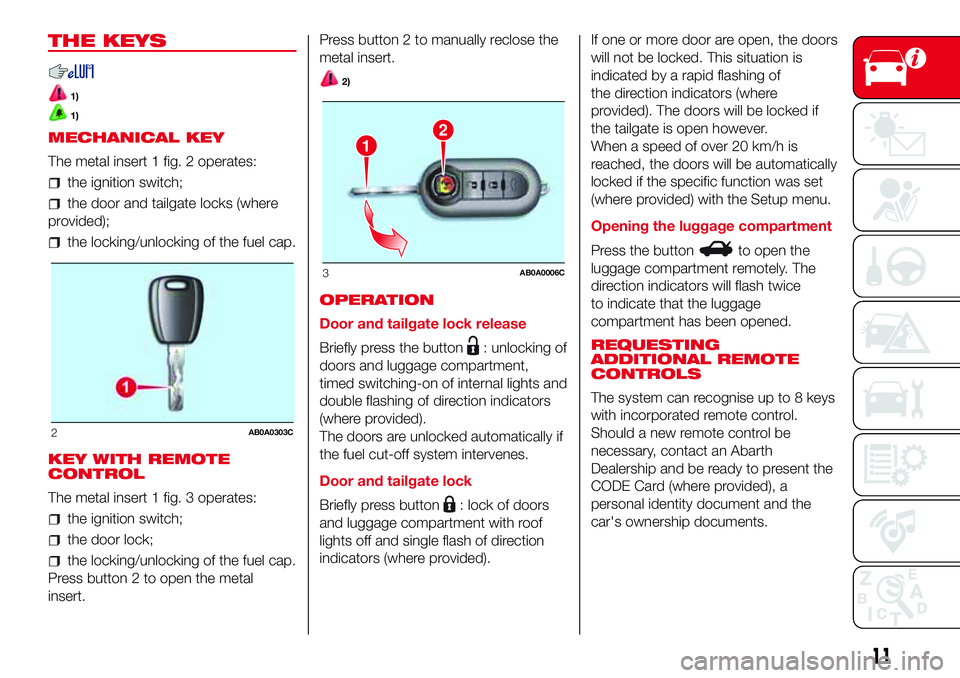
The metal insert 1 fig. 2 operates:
the ignition switch;
the door and tailgate locks (where
provided);
the locking/unlocking of the fuel cap.
KEY WITH REMOTE
CONTROL
The metal insert 1 fig. 3 operates:
the ignition switch;
the door lock;
the locking/unlocking of the fuel cap.
Press button 2 to open the metal
insert.Press button 2 to manually reclose the
metal insert.
2)
OPERATION
Door and tailgate lock release
Briefly press the button
: unlocking of
doors and luggage compartment,
timed switching-on of internal lights and
double flashing of direction indicators
(where provided).
The doors are unlocked automatically if
the fuel cut-off system intervenes.
Door and tailgate lock
Briefly press button
: lock of doors
and luggage compartment with roof
lights off and single flash of direction
indicators (where provided).If one or more door are open, the doors
will not be locked. This situation is
indicated by a rapid flashing of
the direction indicators (where
provided). The doors will be locked if
the tailgate is open however.
When a speed of over 20 km/h is
reached, the doors will be automatically
locked if the specific function was set
(where provided) with the Setup menu.
Opening the luggage compartment
Press the button
to open the
luggage compartment remotely. The
direction indicators will flash twice
to indicate that the luggage
compartment has been opened.
REQUESTING
ADDITIONAL REMOTE
CONTROLS
The system can recognise up to 8 keys
with incorporated remote control.
Should a new remote control be
necessary, contact an Abarth
Dealership and be ready to present the
CODE Card (where provided), a
personal identity document and the
car's ownership documents.
2AB0A0303C
12
3AB0A0006C
11
Page 16 of 192
DOORS
7)
1)
DOOR CENTRAL
LOCKING/UNLOCKING
Door unlocking from the outside
Press the
button on the key or turn
the metal insert (located inside the key)
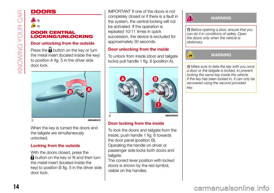
to position A fig. 5 in the driver side
door lock.
When the key is turned the doors and
the tailgate are simultaneously
unlocked.
Locking from the outside
With the doors closed, press the
button on the key or fit and then turn
the metal insert (located inside the
key) to position B fig. 5 in the driver side
door lock.IMPORTANT If one of the doors is not
completely closed or if there is a fault in
the system, the central locking will not
be activated. If the operation is
repeated 10/11 times in quick
succession, the device is excluded for
approximately 30 seconds.
Door unlocking from the inside
To unlock from inside (door and tailgate
locks) pull handle 1 fig. 6 (position A).
Door locking from the inside
To lock the doors and tailgate from the
inside, push handle 1 fig. 6 towards
the door panel (position B).
Operating the handle on driver or
passenger side locks both doors and
tailgate.
The correct lever position with locked
doors is shown by the red symbol,
visible on the handles.
WARNING
7)Before opening a door, ensure that you
can do it in conditions of safety. Open
the doors only when the vehicle is
stationary.
WARNING
1)Make sure to take the key with you once
a door or the tailgate is locked, to prevent
locking the same key inside the vehicle.
If the key has been locked in, it can only be
recovered using the second provided
key.
BA
5AB0A0041C
AB
1
6AB0A0304C
14
KNOWING YOUR CAR
Page 20 of 192
10)Once you have released the
adjustment lever, always check that the
seat is locked on the guides by trying
to move it back and forth. If the seat is not
locked into place, it may unexpectedly
slide and cause the driver to lose control of
the car.
11)Make sure the backrests are properly
secured at both sides to prevent them from
moving forward, in the event of sharp
braking, with possible impact with of the
passengers.
WARNING
2)The fabric upholstery of the seats has
been designed to withstand long-term
wear deriving from normal use of the car.
Some precautions are however required.
Avoid prolonged and/or excessive rubbing
against clothing accessories such as
metal buckles and Velcro strips which, by
applying a high pressure on the fabric in
a small area, could cause it to break,
thereby damaging the upholstery.
3)Before tilting the backrest, remove any
objects on the seat cushion.
HEAD RESTRAINTS
REAR
(where provided)
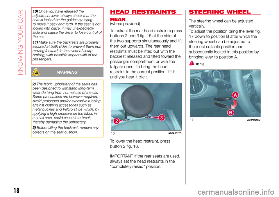
To extract the rear head restraints press
buttons 2 and 3 fig. 16 at the side of
the two supports simultaneously and lift
them out upwards. The rear head
restraints must be lifted out with the
backrest released and tilted toward the
passenger compartment or with the
tailgate open. To bring the head
restraint to the correct position, lift it
until you hear it click.
To lower the head restraint, press
button 2 fig. 16.
IMPORTANT If the rear seats are used,
always set the head restraints in the
"completely raised" position.
STEERING WHEEL
The steering wheel can be adjusted
vertically.
To adjust the position bring the lever fig.
17 down to position B after which the
steering wheel can be adjusted to
the most suitable position and
subsequently locked in this position by
bringing lever to position A.
12) 13)
16AB0A0017C
17AB0A0018C
18
KNOWING YOUR CAR
Page 34 of 192
If requested by the user, the heated
rear window is only turned on if the
soft top is fully closed. If the soft top is
closed incorrectly, the heated rear
window does not operate and
the relevant warning light does not
come on.
Do not remove ice from the soft top
with a sharp item.
To prevent damage, do not use
scrapers or sprays to remove ice from
the heated rear window.
Do not put objects on the soft top:
they could fall if the it is operated,
causing damage and injury.
It is advisable to cover the soft top
with a protective sheet if the car is
left parked in the open for a long time.
Do not keep the soft top folded for a
long time: this could cause folds and
creases in the fabric.
Before moving the soft top, check
that there is enough room to carry
out the operation and that there are no
hindrances or people close to the
moving parts of the soft top.
The cooled air flow into the
passenger compartment may decrease
if the automatic climate control system
is on and the top is not completely
closed.
With the soft top open and the car
travelling, the voice recognition system
may not recognise voice commands
because of the background noise: with
the soft top closed and at a high speed,
the voice function for number dialling
may not be recognised.
EMERGENCY OPERATION
If the switches fail, the soft top can be
moved manually proceeding as
described below:
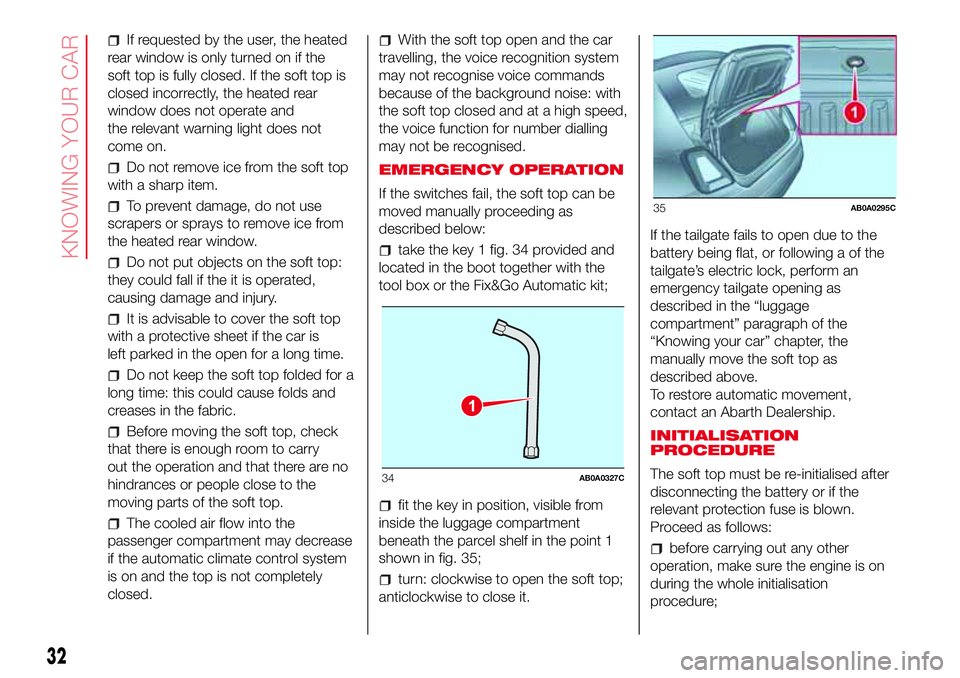
take the key 1 fig. 34 provided and
located in the boot together with the
tool box or the Fix&Go Automatic kit;
fit the key in position, visible from
inside the luggage compartment
beneath the parcel shelf in the point 1
shown in fig. 35;
turn: clockwise to open the soft top;
anticlockwise to close it.If the tailgate fails to open due to the
battery being flat, or following a of the
tailgate’s electric lock, perform an
emergency tailgate opening as
described in the “luggage
compartment” paragraph of the
“Knowing your car” chapter, the
manually move the soft top as
described above.
To restore automatic movement,
contact an Abarth Dealership.
INITIALISATION
PROCEDURE
The soft top must be re-initialised after
disconnecting the battery or if the
relevant protection fuse is blown.
Proceed as follows:
before carrying out any other
operation, make sure the engine is on
during the whole initialisation
procedure;
1
34AB0A0327C
35AB0A0295C
32
KNOWING YOUR CAR
Page 38 of 192
LUGGAGE
COMPARTMENT
30) 31)
OPENING THE TAILGATE
WITH THE REMOTE
CONTROL
Press button
on the key with the
remote control.
The direction indicators will blink twice
when the tailgate is opened.
On some versions, opening the tailgate
will switch the luggage compartment
light on: the light will switch off
automatically when the tailgate is
closed.
12)
32)
ELECTRIC HANDLE
(SOFT TOUCH)
The tailgate (if unlocked) can be opened
from the outside by using the electric
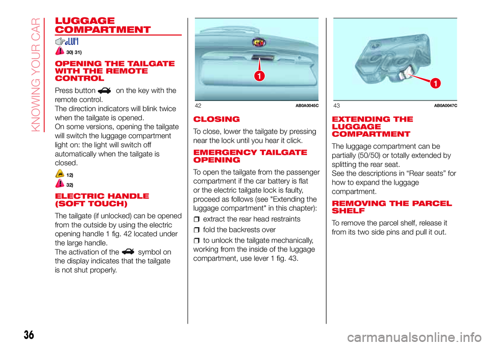
opening handle 1 fig. 42 located under
the large handle.
The activation of the
symbol on
the display indicates that the tailgate
is not shut properly.CLOSING
To close, lower the tailgate by pressing
near the lock until you hear it click.
EMERGENCY TAILGATE
OPENING
To open the tailgate from the passenger
compartment if the car battery is flat
or the electric tailgate lock is faulty,
proceed as follows (see "Extending the
luggage compartment" in this chapter):
extract the rear head restraints
fold the backrests over
to unlock the tailgate mechanically,
working from the inside of the luggage
compartment, use lever 1 fig. 43.EXTENDING THE
LUGGAGE
COMPARTMENT
The luggage compartment can be
partially (50/50) or totally extended by
splitting the rear seat.
See the descriptions in “Rear seats” for
how to expand the luggage
compartment.
REMOVING THE PARCEL
SHELF
To remove the parcel shelf, release it
from its two side pins and pull it out.
1
42AB0A0045C
1
43AB0A0047C
36
KNOWING YOUR CAR
Page 39 of 192
WARNING
30)Never exceed the maximum allowed
load in the luggage compartment, see
chapter “Technical specifications”. Also
make sure that the objects you place in the
luggage compartment have been properly
secured, to avoid them from being thrown
forward consequent to sudden braking
and injuring your passengers.
31)If you are travelling in areas with few
filling stations and you want to transport
fuel in a spare tank, comply with the law by
using only an approved, suitably secured
tank. In the event of a collision the fire
risk is increased all the same.
32)Do not drive with the tailgate open as
exhaust fumes may enter the vehicle.
WARNING
12)Be careful not to hit objects on the
storage shelf when you open the tailgate.
37
Page 53 of 192

INSTRUMENT PANEL WARNING SYMBOLS
Symbol What it means
DOORS/BONNET/LUGGAGE COMPARTMENT OPEN
The symbols on the display switches on, together with a dedicated message, on some versions, when one
or more doors, the tailgate or the bonnet (where provided) are not properly closed. An acoustic signal is
also emitted with the doors open and the car in motion.
LOW BATTERY CHARGE
If the warning light or the symbol on the display (together with a dedicated message on the display on
some versions) remains on, contact an Abarth Dealership immediately.
INSUFFICIENT ENGINE OIL PRESSURE/ENGINE OIL DETERIORATED
When the key is turned to MAR the icon appears (where present), but should disappear as soon as the
engine is started.
NOTE Where present, the warning light may be amber
Low engine oil pressure
The symbol appears continuously together with the message on the display (where present) when the
system detects that the engine oil pressure is insufficient.
36)
51
Page 99 of 192
turn the bulb holder anticlockwise,
extract the press-fitted bulb and
replace it;
refit the bulb holder in the lens, then
position the light, ensuring that the
fastening clip clicks into place.
DIPPED HEADLIGHTS
To replace the bulb, proceed as follows:
turn the protection cap 2 fig. 82
anticlockwise and remove it;
disconnect the connector 1 fig. 86
and release the bulb holder;
extract the bulb and replace it;
refit the bulb in its seat and
reconnect the connector;
refit the protection cap in its housing
and turn clockwise.
121)
MAIN BEAM HEADLIGHTS
To replace the bulb, proceed as
follows:
remove the protective rubber cap
mentioned above;
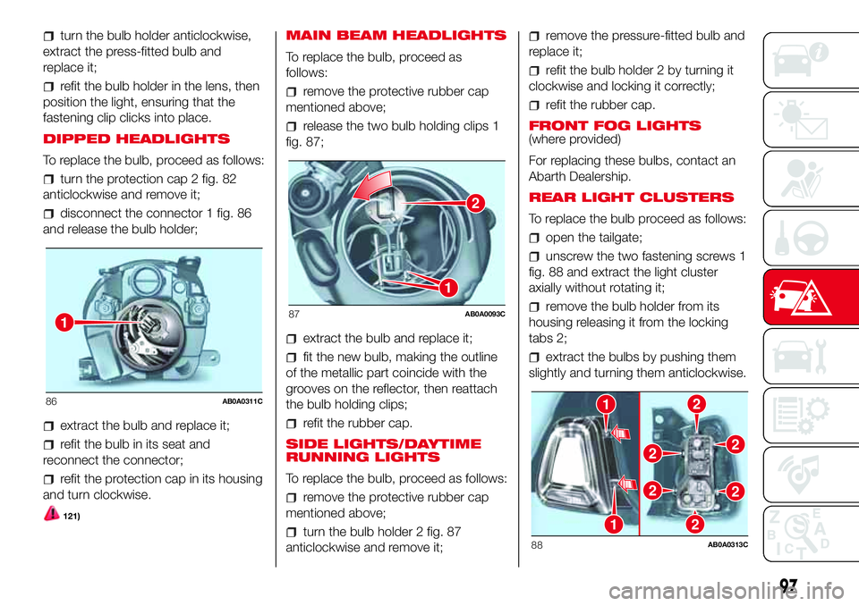
release the two bulb holding clips 1
fig. 87;
extract the bulb and replace it;
fit the new bulb, making the outline
of the metallic part coincide with the
grooves on the reflector, then reattach
the bulb holding clips;
refit the rubber cap.
SIDE LIGHTS/DAYTIME
RUNNING LIGHTS
To replace the bulb, proceed as follows:
remove the protective rubber cap
mentioned above;
turn the bulb holder 2 fig. 87
anticlockwise and remove it;
remove the pressure-fitted bulb and
replace it;
refit the bulb holder 2 by turning it
clockwise and locking it correctly;
refit the rubber cap.
FRONT FOG LIGHTS
(where provided)
For replacing these bulbs, contact an
Abarth Dealership.
REAR LIGHT CLUSTERS
To replace the bulb proceed as follows:
open the tailgate;
unscrew the two fastening screws 1
fig. 88 and extract the light cluster
axially without rotating it;
remove the bulb holder from its
housing releasing it from the locking
tabs 2;
extract the bulbs by pushing them
slightly and turning them anticlockwise.
1
86AB0A0311C
2
1
87AB0A0093C
21
1
22
22
2
88AB0A0313C
97
Page 125 of 192

BATTERY
The car is fitted with a low-maintenance
battery: no electrolyte top-ups with
distilled water are needed in standard
conditions of use.
INSPECTING THE
CHARGE AND THE
ELECTROLYTE LEVEL
The operations must be carried out as
described in this Owner Handbook only
by specialised personnel. Any top-up
operations must be carried out by
skilled personnel and by an Abarth
Dealership.
REPLACING THE
BATTERY
142) 143) 144) 145)
34)
5)If required, replace the battery with a
genuine spare part with the same
specifications.
If a battery with different specifications
is fitted, the service intervals given in
the "Scheduled Servicing Plan" will no
longer be valid.
Follow the battery manufacturer's
instructions for maintenance.USEFUL ADVICE FOR
EXTENDING THE LIFE OF
YOUR BATTERY
To avoid draining your battery and
make it last longer, observe the
following instructions:
when you park the car, ensure that
the doors, tailgate and bonnet are
closed properly, to prevent any lights
from remaining on inside the
passenger's compartment;
switch off all roof lights inside the
car: the car is however equipped with a
system which switches all internal
lights off automatically;
do not keep accessories (e.g.
Uconnect™, hazard warning lights,
etc.) switched on for a long time when
the engine is not running;
before performing any operation on
the electrical system, disconnect the
negative battery pole;
completely tighten the battery
terminals.
IMPORTANT If the charge level remains
under 50% for a long time, the battery
is damaged by sulphation, reducing
its capacity and efficiency at start-up.The battery will also be more at risk of
freezing (this can happen as early as
-10°C). Refer to the paragraph "Car
inactivity" in "Starting and driving" if the
car is left parked for a long time.
If after buying the car, you want to
install electrical accessories that require
permanent electrical supply (alarm,
etc.) or accessories that in any case
burden the electrical supply, contact an
Abarth Dealership whose qualified
personnel, in addition to suggesting the
most suitable devices available in
Lineaccessori Abarth, will evaluate the
overall electric consumption, checking
whether the car’s electrical system is
capable of withstanding the load
required, or whether it should
be integrated with a more powerful
battery.
Since some of these devices continue
to consume electricity even when
the engine is off, they gradually run
down the battery.
WARNING
142)Battery fluid is poisonous and
corrosive. Avoid contact with skin and
eyes. Keep naked flames and sources of
sparks away from the battery: risk of
explosion and fire.
123
Page 135 of 192

IDENTIFICATION
DATA
The following identification codes are
printed and shown on the plates:
VIN plate.
Chassis marking.
Bodywork paint identification plate.
Engine marking.
VEHICLE IDENTIFICATION
NUMBER (VIN) PLATE
The data plate is located on the left side
of the rear part of the luggage
compartment floor and it bears the
following identification data fig. 115:
AName of Manufacturer
BType-approval number.
CVehicle type identification code.
DChassis serial number.
EMaximum authorised weight of fully
laden vehicle.
FMaximum authorised weight of fully
laden vehicle plus trailer.
GMaximum permitted weight on first
axle (front).
HMaximum permitted weight on
second axle (rear).
IEngine type.
LBodywork version code.
MSpare part number.
CHASSIS MARKING
The plate is located on the right side of
the luggage compartment floor and it
bears the following data fig. 116:
vehicle type;
chassis serial number.BODYWORK PAINT
IDENTIFICATION PLATE
The plate is applied on the external
tailgate post (left side) and it bears the
following data fig. 117:
APaint manufacturer.
BColour name.
CColour code.
DRespray and touch up code.
ENGINE MARKING
It is stamped on the cylinder block and
includes the type and the engine serial
number.
115AB0A0346C
116AB0A0345C
117AB0A0344C
133