ACURA NSX 1997 Service Repair Manual
Manufacturer: ACURA, Model Year: 1997, Model line: NSX, Model: ACURA NSX 1997Pages: 1503, PDF Size: 57.08 MB
Page 471 of 1503
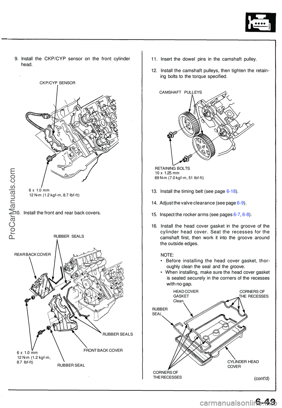
9. Instal l th e CKP/CY P senso r o n th e fron t cylinde r
head .
CKP/CY P SENSO R
6 x 1. 0 m m12 N- m (1. 2 kgf-m , 8. 7 Ibf-ft )
10. Instal l th e fron t an d rea r bac k covers .
RUBBE R SEAL S
REA R BAC K COVE R
6 x 1. 0 m m12 N- m (1. 2 kgf-m ,
8. 7 Ibf-ft ) RUBBE
R SEAL S
FRON T BAC K COVE R
RUBBE R SEA L
11. Inser t th e dowe l pin s i n th e camshaf t pulley .
12 . Instal l th e camshaf t pulleys , the n tighte n th e retain -
in g bolt s t o th e torqu e specified .
CAMSHAF T PULLEY S
RETAININ G BOLT S
10 x 1.25 mm69 N- m (7. 0 kgf-m , 5 1 Ibf-ft )
13. Instal l th e timin g bel t (se e pag e 6-18 ).
14 . Adjus t th e valv e clearanc e (se e pag e 6-9 ).
15 . Inspec t th e rocke r arm s (se e page s 6-7 , 6-8 ).
16 . Instal l th e hea d cove r gaske t i n th e groov e o f th e
cylinde r hea d cover . Sea t th e recesse s fo r th e
camshaf t first , the n wor k i t int o th e groov e aroun d
th e outsid e edges .
NOTE:
• Befor e installin g th e hea d cove r gasket , thor -
oughl y clea n th e sea l an d th e groove .
• Whe n installing , mak e sur e th e hea d cove r gaske t
i s seate d securel y i n th e corner s o f th e recesse s
with n o gap .
HEA D COVE RGASKE TClean.
RUBBE RSEAL
CORNER S O F
TH E RECESSE S
CYLINDER HEA DCOVE R
CORNER S O F
TH E RECESSE S
(cont'd)
ProCarManuals.com
Page 472 of 1503
Camshafts
Installation (cont'd)
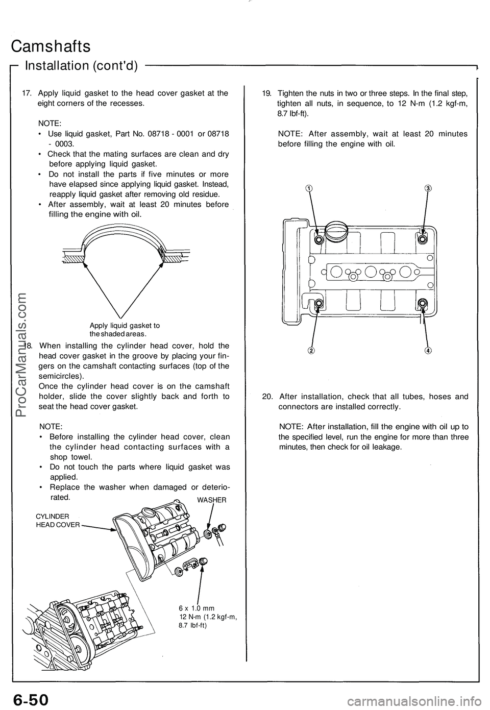
17. Apply liquid gasket to the head cover gasket at the
eight corners of the recesses.
NOTE:
• Use liquid gasket, Part No. 08718 - 0001 or 08718
- 0003.
• Check that the mating surfaces are clean and dry
before applying liquid gasket.
• Do not install the parts if five minutes or more
have elapsed since applying liquid gasket. Instead,
reapply liquid gasket after removing old residue.
• After assembly, wait at least 20 minutes before
filling the engine with oil.
Apply liquid gasket to
the shaded areas.
18. When installing the cylinder head cover, hold the
head cover gasket in the groove by placing your fin-
gers on the camshaft contacting surfaces (top of the
semicircles).
Once the cylinder head cover is on the camshaft
holder, slide the cover slightly back and forth to
seat the head cover gasket.
NOTE:
• Before installing the cylinder head cover, clean
the cylinder head contacting surfaces with a
shop towel.
• Do not touch the parts where liquid gasket was
applied.
• Replace the washer when damaged or deterio-
rated.
CYLINDER
HEAD COVER
WASHER
6 x 1.0 mm
12 N-m (1.2 kgf-m,
8.7 Ibf-ft)
19. Tighten the nuts in two or three steps. In the final step,
tighten all nuts, in sequence, to 12 N-m (1.2 kgf-m,
8.7 Ibf-ft).
NOTE: After assembly, wait at least 20 minutes
before filling the engine with oil.
20. After installation, check that all tubes, hoses and
connectors are installed correctly.
NOTE: After installation, fill the engine with oil up to
the specified level, run the engine for more than three
minutes, then check for oil leakage.ProCarManuals.com
Page 473 of 1503
7-6
7-1 8
7-1 8
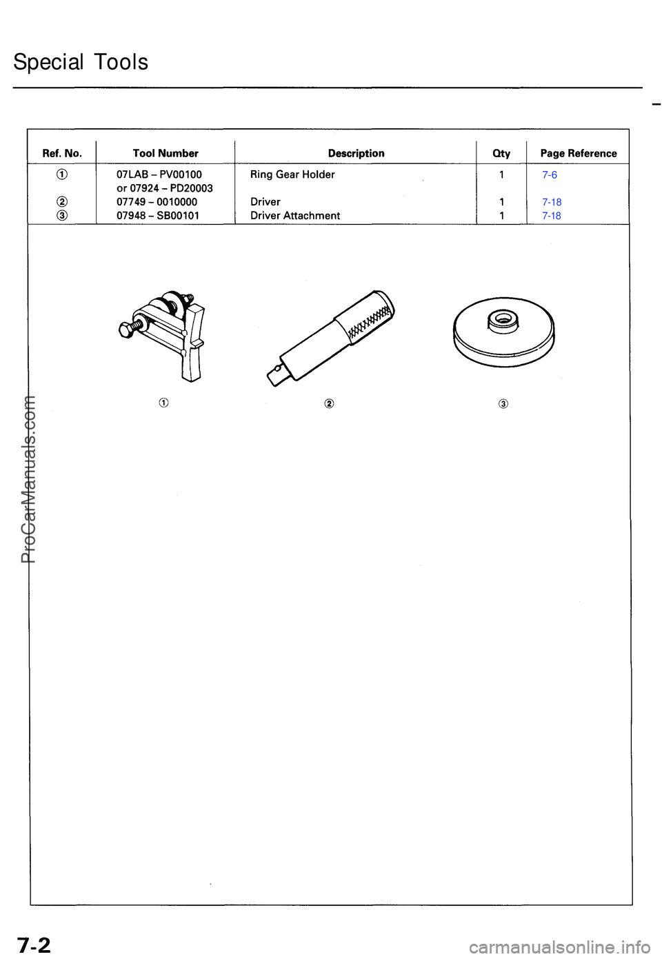
Specia l Tool s
ProCarManuals.com
Page 474 of 1503
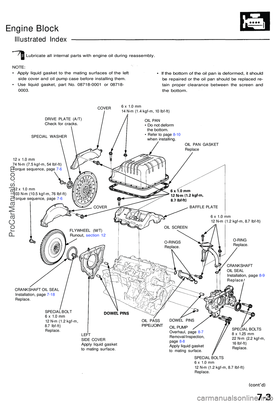
Engine Bloc k
Illustrate d Inde x
Lubricat e al l interna l part s wit h engin e oi l durin g reassembly .
NOTE:
• Appl y liqui d gaske t t o th e matin g surface s o f th e lef t
side cove r an d oi l pum p cas e befor e installin g them .
• Us e liqui d gasket , par t No . 0871 8-000 1 o r 0871 8-
0003 .
• I f th e botto m of th e oi l pa n is deformed , i t shoul d
be repaire d o r th e oi l pa n shoul d b e replace d re -
tain prope r clearanc e betwee n th e scree n an d
the bottom .
COVER
DRIV E PLAT E (A/T )
Check fo r cracks .
SPECIA L WASHER
12 x 1. 0 m m74 N- m (7. 5 kgf-m , 5 4 Ibf-ft )
Torqu e sequence , pag e 7- 6
12 x 1. 0 m m103 N- m (10. 5 kgf-m , 7 6 Ibf-ft )
Torqu e sequence , pag e 7- 6
6 x 1. 0 m m14 N- m (1. 4 kgf-m , 1 0 Ibf-ft )
OIL PA N• D o no t defor mthe bottom .• Refe r t o pag e 8-1 0whe n installing .
OIL PA N GASKE T
Replac e
6 x 1. 0 m m12 N- m (1. 2 kgf-m , 8. 7 Ibf-ft )
O-RIN G
Replace .
CRANKSHAF T
OI L SEA L
Installation , pag e 8- 9Replace .
CRANKSHAF T OI L SEA L
Installation , pag e 7-1 8Replace .
SPECIAL BOL T6 x 1. 0 m m12 N- m (1. 2 kgf-m ,8.7 Ibf-ft )Replace .
OIL PAS SPIPE/JOIN T
LEFTSIDE COVE RApply liqui d gaske tto matin g surface .
DOWEL PIN S
OIL PUM POverhaul , pag e 8- 7
Removal/Inspection ,
pag e 8- 8
Appl y liqui d gaske tto matin g surface . SPECIA
L BOLT S
8 x 1.2 5 mm22 N- m (2. 2 kgf-m ,
1 6 Ibf-ft )
Replace .
SPECIAL BOLT S6 x 1. 0 m m12 N- m (1. 2 kgf-m , 8. 7 Ibf-ft )Replace .
FLYWHEE L (M/T )Runout , sectio n 1 2
COVE R
OIL SCREE N
O-RING S
Replace .BAFFL
E PLAT E
ProCarManuals.com
Page 475 of 1503
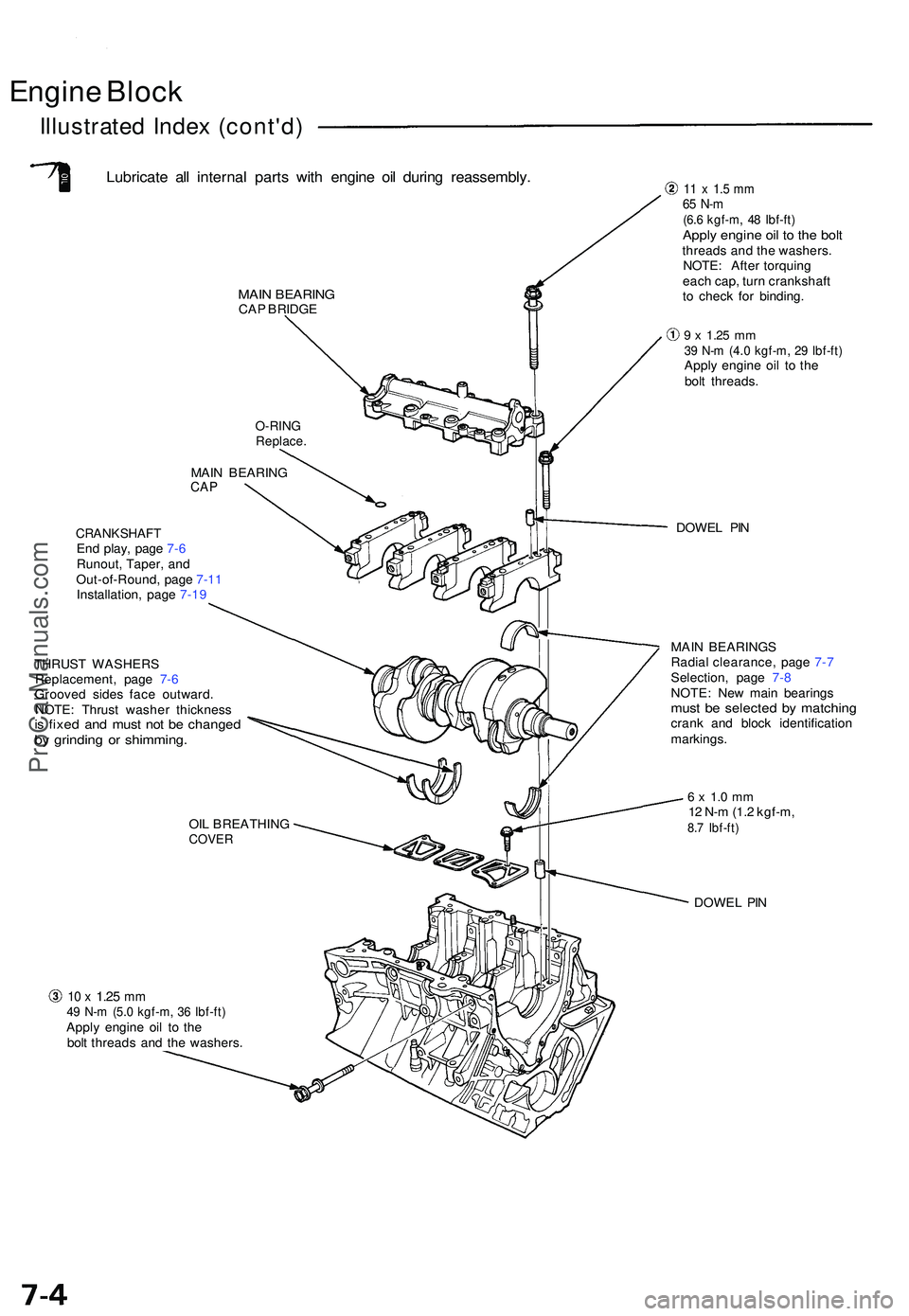
Engine Bloc k
Illustrate d Inde x (cont'd )
Lubricate al l interna l part s wit h engin e oi l durin g reassembly .
MAIN BEARIN GCAP BRIDG E
MAI N BEARIN G
CAP
CRANKSHAF TEnd play , pag e 7- 6
Runout , Taper , an d
Out-of-Round , pag e 7-1 1
Installation , pag e 7-1 9
THRUS T WASHER S
Replacement , pag e 7- 6
Groove d side s fac e outward .
NOTE : Thrus t washe r thicknes s
is fixe d an d mus t no t b e change dby grindin g o r shimming .
10 x 1.2 5 mm49 N- m (5. 0 kgf-m , 3 6 Ibf-ft )Apply engin e oi l t o th e
bol t thread s an d th e washers .
11 x 1. 5 m m65 N- m(6.6 kgf-m , 4 8 Ibf-ft )Apply engin e oi l t o th e bol tthread s an d th e washers .
NOTE : Afte r torquin g
eac h cap , tur n crankshaf t
t o chec k fo r binding .
9 x 1.2 5 mm39 N- m (4. 0 kgf-m , 2 9 Ibf-ft )Apply engin e oi l t o th e
bol t threads .
DOWE L PI N
MAI N BEARING S
Radia l clearance , pag e 7- 7
Selection , pag e 7- 8
NOTE : Ne w mai n bearing s
must b e selecte d b y matchin gcrank an d bloc k identificatio n
markings .
6 x 1. 0 m m12 N- m (1. 2 kgf-m ,8.7 Ibf-ft )
DOWE L PI N
OI
L BREATHIN G
COVER
O-RIN GReplace .
ProCarManuals.com
Page 476 of 1503
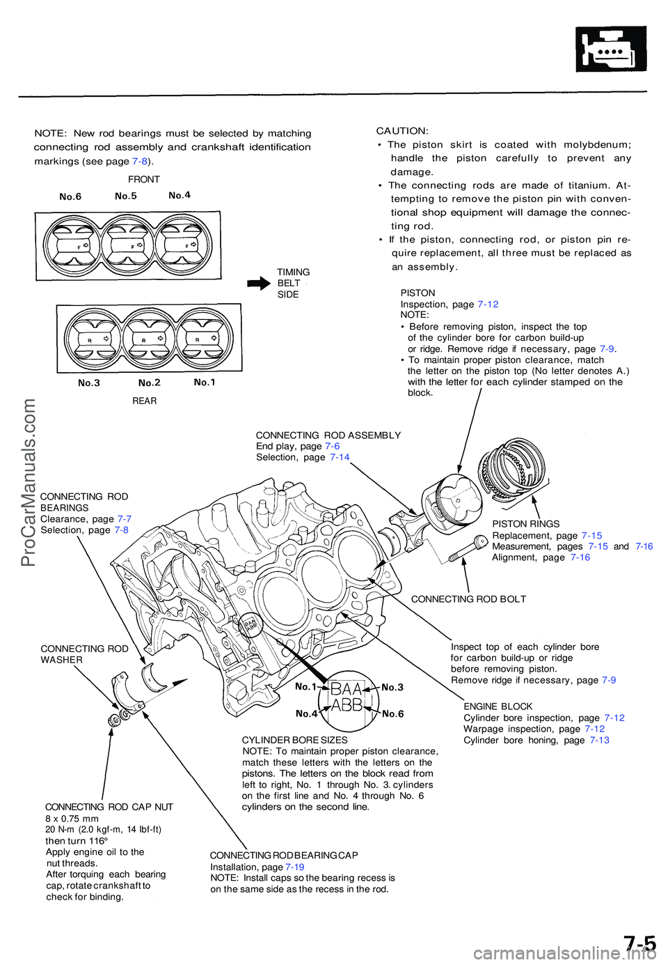
NOTE: Ne w ro d bearing s mus t b e selecte d b y matchin g
connectin g ro d assembl y an d crankshaf t identificatio n
markings (se e pag e 7-8 ).
TIMIN GBELTSIDE
CAUTION :
• Th e pisto n skir t i s coate d wit h molybdenum ;
handle th e pisto n carefull y t o preven t an y
damage .
• Th e connectin g rod s ar e mad e o f titanium . At -
temptin g t o remov e th e pisto n pi n wit h conven -
tional sho p equipmen t wil l damag e th e connec -
ting rod .
• I f th e piston , connectin g rod , o r pisto n pi n re -
quir e replacement , al l thre e mus t b e replace d a s
an assembly .
PISTONInspection , pag e 7-1 2NOTE :• Befor e removin g piston , inspec t th e to p
o f th e cylinde r bor e fo r carbo n build-u p
o r ridge . Remov e ridg e i f necessary , pag e 7-9 .
• T o maintai n prope r pisto n clearance , matc h
th e lette r o n th e pisto n to p (N o lette r denote s A. )
with th e lette r fo r eac h cylinde r stampe d o n th eblock .
CONNECTIN G RO D ASSEMBL Y
End play , pag e 7- 6Selection , pag e 7-1 4
CONNECTIN G RO D
BEARING SClearance , pag e 7- 7
Selection , pag e 7- 8 PISTO
N RING S
Replacement , pag e 7-1 5
Measurement , page s 7-1 5 an d 7-1 6
Alignment , pag e 7-1 6
CONNECTIN G RO D
WASHE R
CONNECTIN G RO D CA P NU T8 x 0.7 5 m m20 N- m (2. 0 kgf-m , 1 4 Ibf-ft )then tur n 116 °Appl y engin e oi l t o th e
nu t threads .
Afte r torquin g eac h bearin g
cap , rotat e crankshaf t t o
chec k fo r binding . CYLINDE
R BOR E SIZE S
NOTE : T o maintai n prope r pisto n clearance ,
matc h thes e letter s wit h th e letter s o n th e
pistons . Th e letter s o n th e bloc k rea d fro mleft t o right , No . 1 throug h No . 3 . cylinder s
o n th e firs t lin e an d No . 4 throug h No . 6
cylinder s o n th e secon d line .
CONNECTIN G RO D BEARIN G CA P
Installation , pag e 7-1 9
NOTE : Instal l cap s s o th e bearin g reces s is
o n th e sam e sid e a s th e reces s in th e rod . Inspec
t to p o f eac h cylinde r bor e
fo r carbo n build-u p o r ridg e
befor e removin g piston .
Remov e ridg e if necessary , pag e 7- 9
ENGIN E BLOC KCylinde r bor e inspection , pag e 7-12
Warpag e inspection , pag e 7-12
Cylinde r bor e honing , pag e 7-13
CONNECTIN
G RO D BOL T
FRON
T
REAR
ProCarManuals.com
Page 477 of 1503
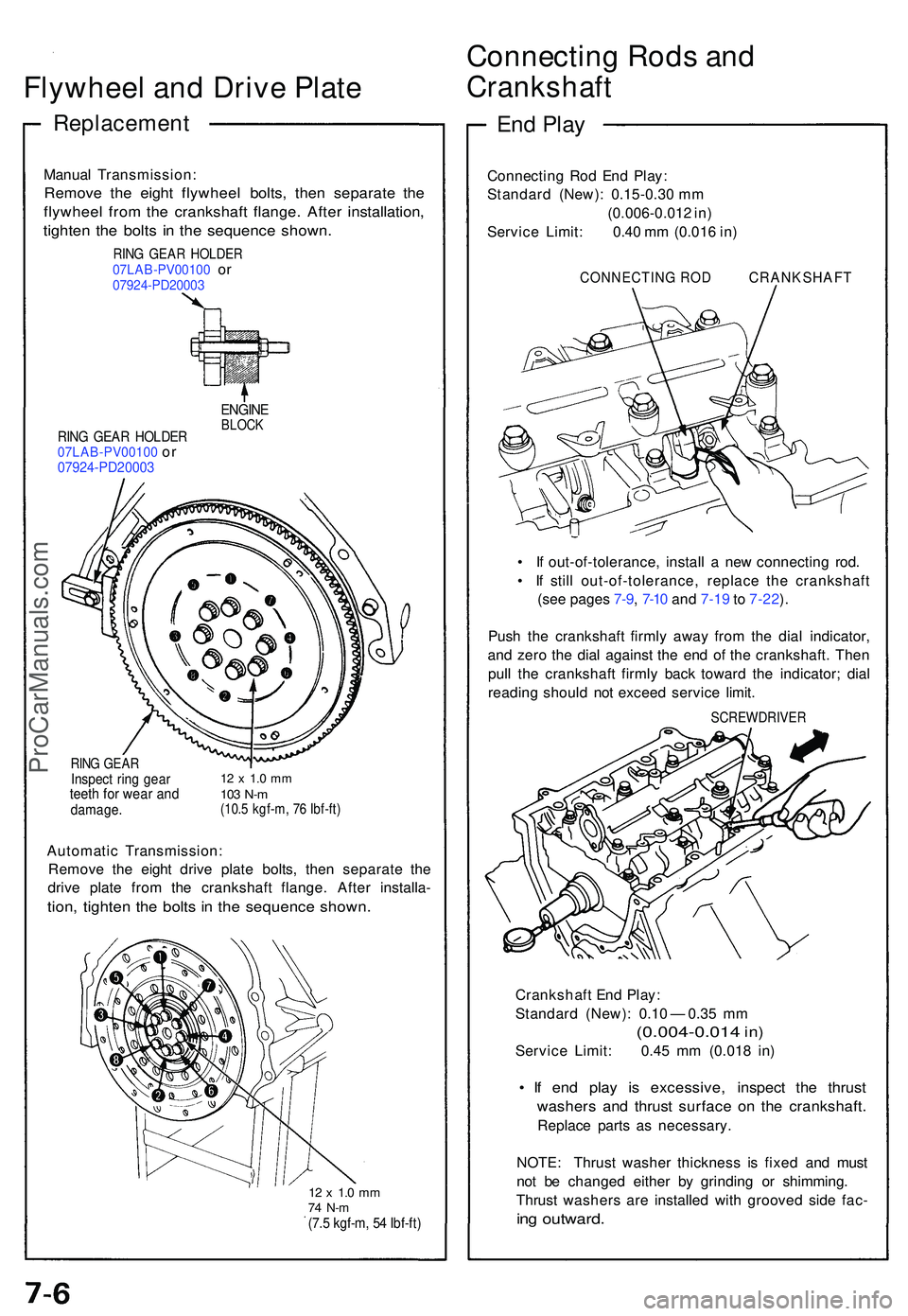
Flywheel an d Driv e Plat e
Replacemen t
Connecting Rod s an d
Crankshaf t
Manual Transmission :
Remove th e eigh t flywhee l bolts , the n separat e th e
flywhee l fro m th e crankshaf t flange . Afte r installation ,
tighten th e bolt s i n th e sequenc e shown .
RING GEA R HOLDE R07LAB-PV0010 0 or07924-PD2000 3
RING GEA R HOLDE R07LAB-PV00100 or07924-PD2000 3
ENGINEBLOCK
RING GEA RInspec t rin g gea rteeth fo r wea r an ddamage .
12 x 1. 0 m m103 N- m(10. 5 kgf-m , 7 6 Ibf-ft )
Automati c Transmission :
Remov e th e eigh t driv e plat e bolts , the n separat e th e
driv e plat e fro m th e crankshaf t flange . Afte r installa -
tion, tighte n th e bolt s i n th e sequenc e shown .
12 x 1. 0 m m74 N- m(7.5 kgf-m , 5 4 Ibf-ft )
End Pla y
Connectin g Ro d En d Play :
Standard (New): 0.15-0.30 mm
(0.006-0.01 2 in )
Servic e Limit : 0.40 m m (0.01 6 in )
CONNECTIN G RO D CRANKSHAF T
• I f out-of-tolerance , instal l a ne w connectin g rod .
• I f stil l out-of-tolerance , replac e th e crankshaf t
(se e page s 7-9 , 7-1 0 an d 7-1 9 to 7-22 ).
Pus h th e crankshaf t firml y awa y fro m th e dia l indicator ,
an d zer o th e dia l agains t th e en d o f th e crankshaft . The n
pul l th e crankshaf t firml y bac k towar d th e indicator ; dia l
readin g shoul d no t excee d servic e limit .
SCREWDRIVE R
Crankshaft En d Play :
Standar d (New) : 0.1 0 — 0.3 5 m m
(0.004-0.01 4 in)
Servic e Limit : 0.4 5 m m (0.01 8 in )
• I f en d pla y i s excessive , inspec t th e thrus t
washer s an d thrus t surfac e o n th e crankshaft .
Replace part s a s necessary .
NOTE : Thrus t washe r thicknes s i s fixe d an d mus t
no t b e change d eithe r b y grindin g o r shimming .
Thrus t washer s ar e installe d wit h groove d sid e fac -
ing outward .
ProCarManuals.com
Page 478 of 1503
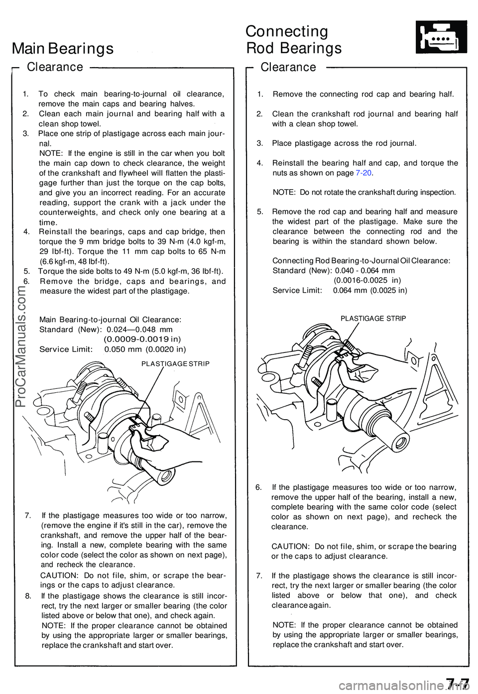
Main Bearing s
Clearanc e
1. T o chec k mai n bearing-to-journa l oi l clearance ,
remov e th e mai n cap s an d bearin g halves .
2 . Clea n eac h mai n journa l an d bearin g hal f wit h a
clea n sho p towel .
3 . Plac e on e stri p o f plastigag e acros s eac h mai n jour -
nal.
NOTE : I f th e engin e i s stil l i n th e ca r whe n yo u bol t
th e mai n ca p dow n t o chec k clearance , th e weigh t
o f th e crankshaf t an d flywhee l wil l flatte n th e plasti -
gag e furthe r tha n jus t th e torqu e o n th e ca p bolts ,
an d giv e yo u a n incorrec t reading . Fo r a n accurat e
reading , suppor t th e cran k wit h a jac k unde r th e
counterweights , an d chec k onl y on e bearin g a t a
time .
4. Reinstal l th e bearings , cap s an d ca p bridge , the n
torqu e th e 9 m m bridg e bolt s t o 3 9 N- m (4. 0 kgf-m ,
2 9 Ibf-ft) . Torqu e th e 1 1 m m ca p bolt s t o 6 5 N- m
(6. 6 kgf-m , 4 8 Ibf-ft) .
5 . Torqu e th e sid e bolt s t o 4 9 N- m (5. 0 kgf-m , 3 6 Ibf-ft) .
6 . Remov e th e bridge , cap s an d bearings , an d
measur e th e wides t par t o f th e plastigage .
Mai n Bearing-to-journa l Oi l Clearance :
Standar d (New) : 0.024—0.04 8 m m
(0.0009-0.0019 in)
Servic e Limit : 0.05 0 m m (0.002 0 in )
PLASTIGAG E STRI P
7. I f th e plastigag e measure s to o wid e o r to o narrow ,
(remov e th e engin e if it' s stil l i n th e car) , remov e th e
crankshaft , an d remov e th e uppe r hal f o f th e bear -
ing . Instal l a new , complet e bearin g wit h th e sam e
colo r cod e (selec t th e colo r a s show n o n nex t page) ,
and rechec k th e clearance .
CAUTION: D o no t file , shim , o r scrap e the bear -
ing s o r th e cap s t o adjus t clearance .
8 . I f th e plastigag e show s th e clearanc e i s stil l incor -
rect , tr y th e nex t large r o r smalle r bearin g (th e colo r
liste d abov e o r belo w tha t one) , an d chec k again .
NOTE : I f th e prope r clearanc e canno t b e obtaine d
b y usin g th e appropriat e large r o r smalle r bearings ,
replac e th e crankshaf t an d star t over .
Connectin g
Rod Bearing s
Clearanc e
1. Remov e th e connectin g ro d ca p an d bearin g half .
2 . Clea n th e crankshaf t ro d journa l an d bearin g hal f
wit h a clea n sho p towel .
3 . Plac e plastigag e acros s th e ro d journal .
4 . Reinstal l th e bearin g hal f an d cap , an d torqu e th e
nut s a s show n o n pag e 7-20 .
NOTE : D o no t rotat e th e crankshaf t durin g inspection .
5 . Remov e th e ro d ca p an d bearin g hal f an d measur e
th e wides t par t o f th e plastigage . Mak e sur e th e
clearanc e betwee n th e connectin g ro d an d th e
bearin g i s withi n th e standar d show n below .
Connectin g Ro d Bearing-to-Journa l Oi l Clearance :
Standar d (New) : 0.04 0 - 0.06 4 m m
(0.0016-0.002 5 in )
Servic e Limit : 0.06 4 m m (0.002 5 in )
PLASTIGAG E STRI P
6. I f th e plastigag e measure s to o wid e o r to o narrow ,
remov e th e uppe r hal f o f th e bearing , instal l a new ,
complet e bearin g wit h th e sam e colo r cod e (selec t
colo r a s show n o n nex t page) , an d rechec k th e
clearance .
CAUTION : D o no t file , shim , o r scrap e th e bearin g
o r th e cap s t o adjus t clearance .
7 . I f th e plastigag e show s th e clearanc e i s stil l incor -
rect , tr y th e nex t large r o r smalle r bearin g (th e colo r
liste d abov e o r belo w tha t one) , an d chec k
clearanc e again .
NOTE : I f th e prope r clearanc e canno t b e obtaine d
b y usin g th e appropriat e large r o r smalle r bearings ,
replac e th e crankshaf t an d star t over .
ProCarManuals.com
Page 479 of 1503
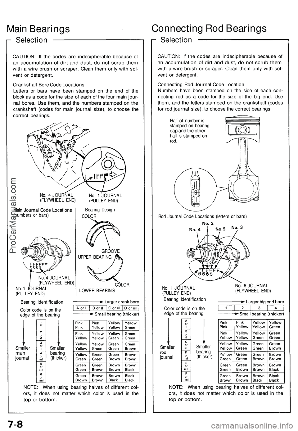
Main Bearing s
Selection
CAUTION : I f th e code s ar e indecipherabl e becaus e o f
an accumulatio n o f dir t an d dust , d o no t scru b the m
with a wir e brus h o r scraper . Clea n the m onl y wit h sol -
ven t o r detergent .
Crankshaf t Bor e Cod e Location s
Letter s o r bar s hav e bee n stampe d o n th e en d o f th e
bloc k a s a cod e fo r th e siz e o f eac h o f th e fou r mai n jour -
nal bores . Us e them , an d th e number s stampe d o n th e
crankshaf t (code s fo r mai n journa l size) , t o choos e th e
correc t bearings .
No. 4 JOURNA L(FLYWHEE L END )
Main Journa l Cod e Location s(numbers o r bars )
No. 4 JOURNA L(FLYWHEE L END )
No. 1 JOURNA L(PULLEY END )
No. 1 JOURNA L(PULLEY END )
Bearin g Desig n
COLOR
GROOV E
UPPER BEARIN G
COLOR
LOWE R BEARIN G
Bearing Identificatio n
Color cod e i s o n th e
edg e o f th e bearin g
Smallermainjourna l
Smalle rbearing(thicker )
NOTE: Whe n usin g bearin g halve s o f differen t col -
ors , i t doe s no t matte r whic h colo r i s use d i n th e
top o r bottom .
Connectin g Ro d Bearing s
Selection
CAUTION : I f th e code s ar e indecipherabl e becaus e o f
an accumulatio n o f dir t an d dust , d o no t scru b the m
with a wir e brus h o r scraper . Clea n the m onl y wit h sol -
ven t o r detergent .
Connectin g Ro d Journa l Cod e Locatio n
Number s hav e bee n stampe d o n th e sid e o f eac h con -
nectin g ro d a s a cod e fo r th e siz e o f th e bi g end . Us e
them , an d th e letter s stampe d o n th e crankshaf t (code s
for ro d journa l size) , t o choos e th e correc t bearings .
Half o f numbe r i sstampe d o n bearin gcap an d th e othe rhalf i s stampe d o nrod .
Rod Journa l Cod e Location s (letter s o r bars )
No. 1 JOURNA L(PULLEY END )
Bearin g Identificatio n
Color cod e i s o n th eedg e o f th e bearin g
No. 6 JOURNA L(FLYWHEE L END )
Smalle rrodjourna l
Smalle rbearing(thicker )
NOTE: Whe n usin g bearin g halve s o f differen t col -
ors, i t doe s no t matte r whic h colo r i s use d i n th e
top o r bottom .
ProCarManuals.com
Page 480 of 1503
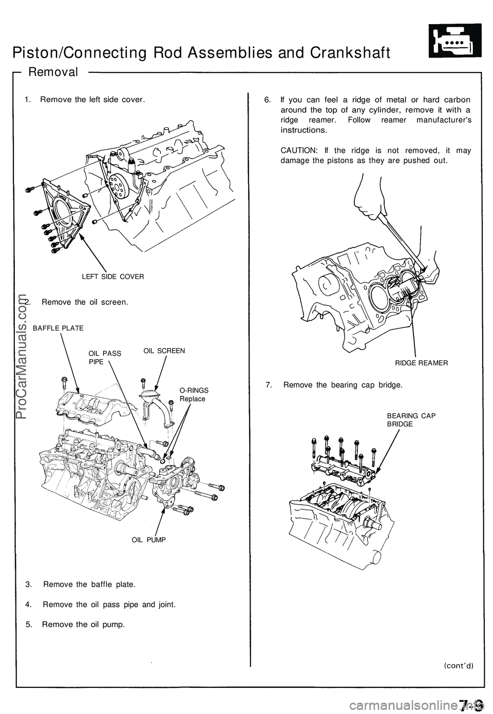
Piston/Connecting Ro d Assemblie s an d Crankshaf t
Removal
1. Remov e th e lef t sid e cover .
LEFT SID E COVE R
2. Remov e th e oi l screen .
BAFFLE PLAT E
OIL SCREE N
O-RING S
Replace
OIL PUM P
3. Remov e th e baffl e plate .
4 . Remov e th e oi l pas s pip e an d joint .
5. Remov e th e oi l pump .
6. I f yo u ca n fee l a ridg e o f meta l o r har d carbo n
around th e to p of an y cylinder , remov e i t wit h a
ridg e reamer . Follo w reame r manufacturer' s
instructions.
CAUTION: I f th e ridg e i s no t removed , i t ma y
damag e th e piston s a s the y ar e pushe d out .
RIDG E REAME R
7. Remov e th e bearin g ca p bridge .
BEARIN G CA PBRIDG E
OIL PAS SPIPE
ProCarManuals.com