ACURA RL KA9 1996 Service Repair Manual
Manufacturer: ACURA, Model Year: 1996, Model line: RL KA9, Model: ACURA RL KA9 1996Pages: 1954, PDF Size: 61.44 MB
Page 261 of 1954
Navigation Syste m
Sympto m Troubleshootin g (cont'd )
DVD scree n erro r message s
Diagnostic Test : Ca r Statu s
NOTE :
• Chec k th e Navigatio n Syste m Owner' s Manua l fo r a
lis t o f commo n DV D scree n erro r message s an d th e
probabl e cause .
• G o int o th e Diagnosti c mod e an d us e th e "Ca r
Status " diagnosti c (se e pag e 23-45 ) t o chec k th e sta -
tus o f th e DV D lid.
1. Chec k th e DVD-RO M readin g surfac e fo r scratches .
Are there scratches?
YES—Replac e th e DVD-RO M (se e pag e 23-52 ).
NO—I f
the proble m occur s occasionally whe n the
syste m is cold , thi s i s normal . I f th e proble m occur s
frequentl y whe n driving , replac e th e navigatio n uni t
(se e pag e 23-53 ).
Navigatio n canno t contro l A/ C
Diagnosti c Test : Navigatio n Syste m Lin k
NOTE :
• Alway s chec k th e connector s fo r poo r connection s o r
loos e terminals .
• Befor e troubleshooting , ge t th e navigatio n syste m
anti-thef t codes .
• Afte r troubleshooting , ente r th e navigatio n syste m
anti-thef t codes .
1. G o int o th e Diagnosti c Mod e an d perfor m th e "Nav i
System Link " chec k (se e pag e 23-40 ).
Is "Air-con " icon red?
YES—D o th e climat e contro l syste m
troubleshooting .
NO—Chec k fo r a n ope n o r shor t t o groun d betwee n
displa y uni t connecto r A (5P ) terminal s No . 2 , No . 3 ,
No . 4 an d climat e contro l uni t (12P ) connecto r termi -
nal s No . 12 , No . 15 , No . 4 . I f OK , chec k th e climat e
contro l syste m fo r norma l operation . I f th e climat e
contro l syste m work s properly , substitut e a known -
goo d displa y uni t an d recheck .
23-36
ProCarManuals.com
Page 262 of 1954
Display day/nigh t mod e doe s no t wor k
Diagnosti c Test : Ca r Statu s
NOTE :
• Alway s chec k th e connector s fo r poo r connection s o r
loos e terminals .
• Befor e troubleshooting , ge t th e navigatio n syste m
anti-thef t codes .
• Afte r troubleshooting , ente r th e navigatio n syste m
anti-thef t codes .
1 . Chang e th e day/nigh t mod e t o "AUTO " unde r Set-up ,
an d recheck .
Doe s the display change to day and night modes?
YES—Th e syste m is O K a t thi s time .
NO—G o to ste p 2 .
2 . G o int o th e Diagnosti c Mod e an d us e diagnosti c th e
"Ca r Status " fo r a n IL L signa l (se e pag e 23-45 ) t o
check .
Is the "ILL" signal OK?
YES—Th e syste m is OK .
NO—Chec k th e IL L + circui t betwee n th e navigatio n
uni t an d tailligh t relay .
System lock s u p constantl y
Diagnostic Test : Uni t Chec k
1. Star t th e engin e an d tur n th e ignitio n switc h OFF ,
the n tur n th e ignitio n switc h O N (II) .
Doe s the system reboot?
YES—Th e syste m is O K a t thi s time .
NO—Chec k th e DV D fo r scratche s o r damag e an d th e
navigatio n uni t fo r wate r damage . I f OK , perfor m al l
o f th e "Uni t check " check s unde r Syste m Diagnosi s
Test (se e pag e 23-43 ).
ProCarManuals.com
Page 263 of 1954
Navigation Syste m
Sympto m Troubleshootin g (cont'd )
Vehicle ico n spin s whe n parke d
Diagnosti c Test : Ya w Rat e
NOTE : Perfor m thi s diagnosti c whe n th e vehicl e i s cold .
1 . G o int o th e Diagnosti c Mod e an d us e th e "Ya w Rate "
diagnosti c (se e pag e 23-47 ).
Are the values correct?
YES—Th e syste m is OK .
NO—Replac e th e navigatio n uni t
(se e pag e 23-53 ).
Navigatio n drive s b y itsel f whe n parke d
Diagnosti c Test : Functiona l Setu p
NOTE :
• Alway s chec k th e connector s fo r poo r connection s o r
loos e terminals .
• Befor e troubleshooting , ge t th e navigatio n syste m
anti-thef t codes .
• Afte r troubleshooting , re-ente r th e anti-thef t code ,
an d re-initializ e th e navigatio n system .
1 . Star t th e engine .
2 . Fro m th e mai n menu , selec t places , the n selec t
an y destination , an d begi n th e trip .
3 . Wit h th e vehicl e parked , watc h th e vehicl e ico n o n
th e display .
Doe s the vehicle position icon move by itself?
YES—G o to ste p 4 .
NO—Th e syste m is O K a t thi s time .
4 . G o int o th e Diagnosti c mode , selec t "Functiona l
Setup" , the n selec t "Demonstration" .
Is "Demonstration Mode" set to "Yes"?
YES—Se t th e Demonstratio n mod e t o "NO" .
NO—Replac e th e navigatio n uni t
(see pag e 23-54 ).
23-3 8ProCarManuals.com
Page 264 of 1954
+
BODY
Navigatio n Stay s o n wit h ignitio n switc h of f
NOTE :
• Alway s chec k th e connector s fo r poo r connection s o r
loos e terminals .
• Befor e troubleshooting , ge t th e navigatio n syste m
anti-thef t codes .
• Afte r troubleshooting , re-ente r th e anti-thef t code ,
an d re-initializ e th e navigatio n system .
1. Wit h th e ke y ou t o f ignition .
Does the navigation screen stay on?
YES—G o to ste p 2 .
NO—Th e syste m is O K a t thi s time .
2 . Th e ca r ma y hav e bee n use d a s a demonstratio n
vehicl e a t a n even t lik e a n aut o show . I n thes e events ,
powe r i s ofte n jumpere d t o th e navigatio n syste m s o
tha t th e ignitio n ke y i s no t neede d i n th e vehicle . A t
th e en d o f th e show , th e jumpe r wir e ma y no t hav e
bee n removed . Chec k th e navigatio n uni t "C " con -
necto r (8P ) fo r a "non-factory " jumpe r wir e in serie s
wit h th e factor y cable .
Is there jumper wire?
YES—Remov e th e jumpe r wire , an d re-test .
NO—G o t o ste p 3 . 3
. Th e displa y o r audi o uni t ma y hav e bee n jumpere d
behin d th e das h t o allo w th e navigatio n syste m to
ru n withou t th e ignitio n key .
Doe s the radio function with the ignition switch off?
YES—G o to ste p 4 .
NO—G o t o ste p 5 .
4 . Remov e th e displa y uni t an d chec k t o se e if th e audi o
uni t connector s hav e a non-factor y jumpe r wir e i n
serie s wit h th e factor y connector .
Is there a jumper wire?
YES—Remov e th e jumpe r wire , an d re-test .
NO—G o to ste p 5 .
5. Chec k th e interio r light s wit h th e ignitio n switc h off .
Can you turn on the interior lights with the ignition
switch off?
YES—Troubleshoo t the AC C circuit .
NO—Replac e th e navigatio n uni t
(se e pag e 23-53 ).
23-3 9
ProCarManuals.com
Page 265 of 1954
Navigation Syste m
System Diagnosi s Mod e
Start-u p procedur e an d Diagnosi s Men u
There ar e tw o way s t o ente r th e diagnosti c mode :
1 . Connec t th e SC S connecto r (se e ste p 2 o n pag e
23-52 ) t o th e navigatio n servic e connecto r focate d
i n th e trunk . Tur n th e ignitio n switc h t o th e O N (II )
position . Th e displa y wil l g o directl y t o th e diagnosti c
men u scree n show n below .
Note : whe n finishe d troubleshooting , mak e sur e t o
remov e th e SC S connector !
2 . Tur n th e ignitio n switc h t o th e O N (II ) position .
Us e th e navigatio n displa y har d button s a s describe d
below :
A . I f th e batter y ha s no t bee n disconnected , the n
pres s an d hol d th e 3 button s (Menu , Map/Guide ,
an d Cancel) , an d kee p the m presse d fo r
approximatel y 5 seconds . Th e displa y scree n wil l
g o directl y t o th e "Selec t Diagnosi s Items " men u
show n below .
B . I f th e batter y wa s disconnecte d an d reconnecte d
prio r t o thi s test , hol d dow n th e Men u an d Zoo m
Ou t button s a t th e "Code " o r "GP S Acquire "
screen . Th e displa y wil l g o t o th e "Nav i Syste m
Link " screen . Pus h th e joystic k t o g o to th e
"Functiona l Setu p menu, " the n touc h th e Retur n
icon t o ge t t o th e "Selec t Diagnosi s Items " menu .
Note : Thi s onl y allow s acces s t o th e diagnosti c
screens . Al l othe r navigatio n function s ar e
disabled .
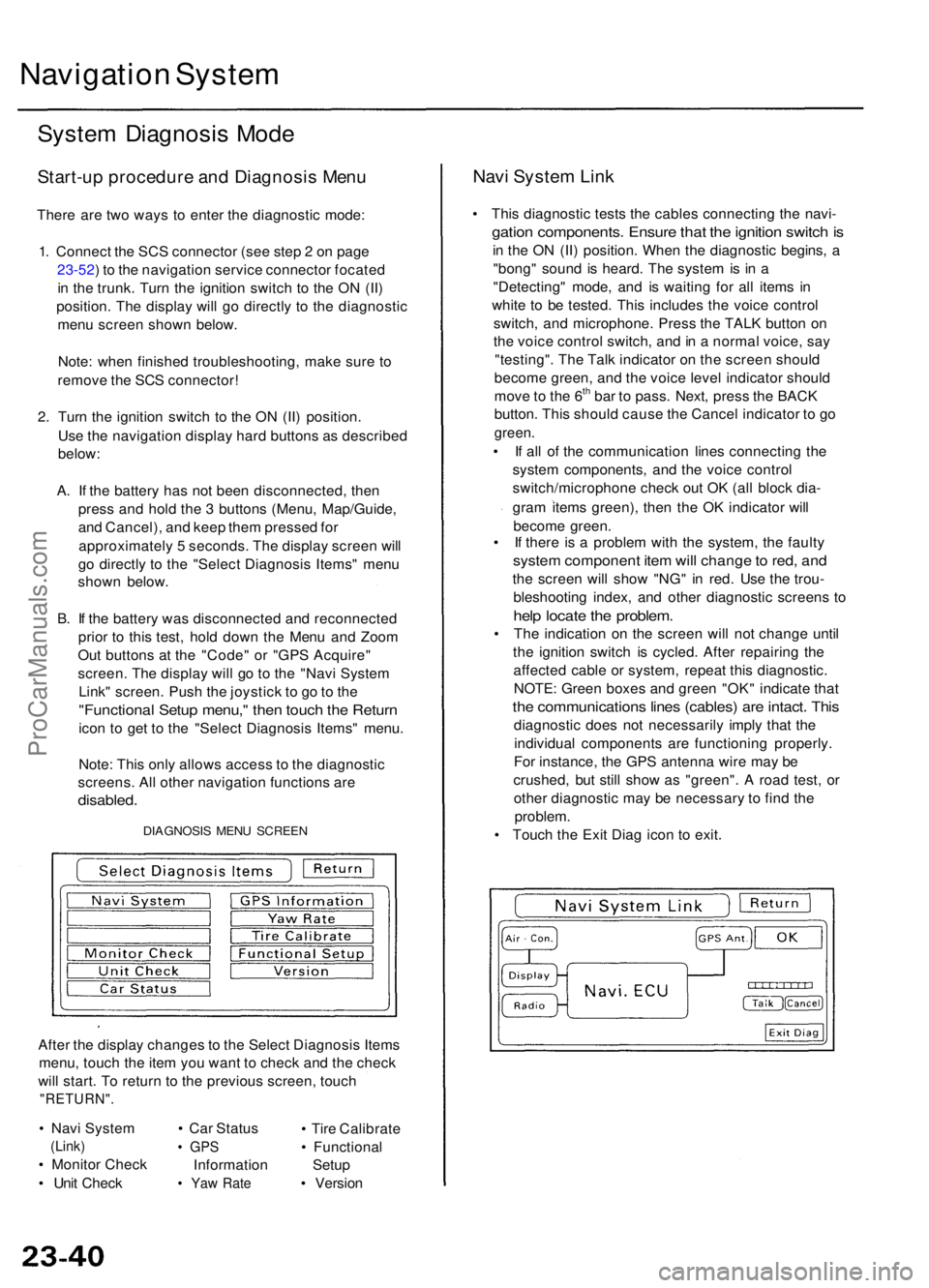
DIAGNOSI S MEN U SCREE N
After th e displa y change s t o th e Selec t Diagnosi s Item s
menu , touc h th e ite m yo u wan t t o chec k an d th e chec k
wil l start . T o retur n t o th e previou s screen , touc h
"RETURN" .
• Nav i Syste m
(Link)
• Monito r Chec k
• Uni t Chec k •
Ca r Statu s
• GP S
Informatio n
• Ya w Rat e
• Tir e Calibrat e
• Functiona l
Setu p
• Versio n
Navi Syste m Lin k
• Thi s diagnosti c test s th e cable s connectin g th e navi -
gation components . Ensur e tha t th e ignitio n switc h is
in th e O N (II ) position . Whe n th e diagnosti c begins , a
"bong " soun d i s heard . Th e syste m is i n a
"Detecting " mode , an d i s waitin g fo r al l item s i n
whit e t o b e tested . Thi s include s th e voic e contro l
switch , an d microphone . Pres s th e TAL K butto n o n
th e voic e contro l switch , an d in a norma l voice , sa y
"testing" . Th e Tal k indicato r o n th e scree n shoul d
becom e green , an d th e voic e leve l indicato r shoul d
mov e to th e 6
th ba r t o pass . Next , pres s th e BAC K
button . Thi s shoul d caus e th e Cance l indicato r t o g o
green .
• I f al l o f th e communicatio n line s connectin g th e
syste m components , an d th e voic e contro l
switch/microphon e chec k ou t O K (al l bloc k dia -
gra m item s green) , the n th e O K indicato r wil l
becom e green .
• I f ther e i s a proble m wit h th e system , th e fault y
system componen t ite m wil l chang e to red , an d
the scree n wil l sho w "NG " i n red . Us e th e trou -
bleshootin g index , an d othe r diagnosti c screen s t o
hel p locat e th e problem .
• Th e indicatio n o n th e scree n wil l no t chang e unti l
th e ignitio n switc h i s cycled . Afte r repairin g th e
affecte d cabl e o r system , repea t thi s diagnostic .
NOTE : Green boxes an d gree n "OK " indicat e tha t
the communication s line s (cables ) ar e intact . Thi s
diagnosti c doe s no t necessaril y impl y tha t th e
individua l component s ar e functionin g properly .
Fo r instance , th e GP S antenn a wir e ma y b e
crushed , bu t stil l sho w a s "green" . A roa d test , o r
othe r diagnosti c ma y b e necessar y t o fin d th e
problem.
• Touc h th e Exi t Dia g ico n t o exit .
ProCarManuals.com
Page 266 of 1954
Monitor Chec k
Overvie w o f displa y uni t
• Th e displa y uni t communicate s wit h th e navigatio n
uni t ove r it s ow n GA-Ne t bus . Informatio n i s sen t t o
th e navigatio n uni t wheneve r th e use r activate s th e
touc h screen , o r har d buttons . Informatio n sen t b y
th e navigatio n uni t t o th e displa y uni t include s com -
mand s t o contro l th e LC D bac k light .
• Th e navigatio n uni t als o send s navigatio n informa -
tion to th e scree n usin g th e Red , Green , Blue , an d
Composit e Vide o signals .
• Th e displa y uni t i s protecte d b y th e securit y syste m
b y daisy-chainin g th e securit y signa l throug h it , an d
the n passin g th e signa l t o th e audi o unit .
• Th e illuminatio n inpu t fro m th e gaug e brightnes s
contro l provide s bac k lightin g fo r th e har d button s
surroundin g th e screen .
• Th e displa y uni t als o communicate s wit h th e climat e
contro l modul e to se t th e A/ C mode , an d fa n speed .
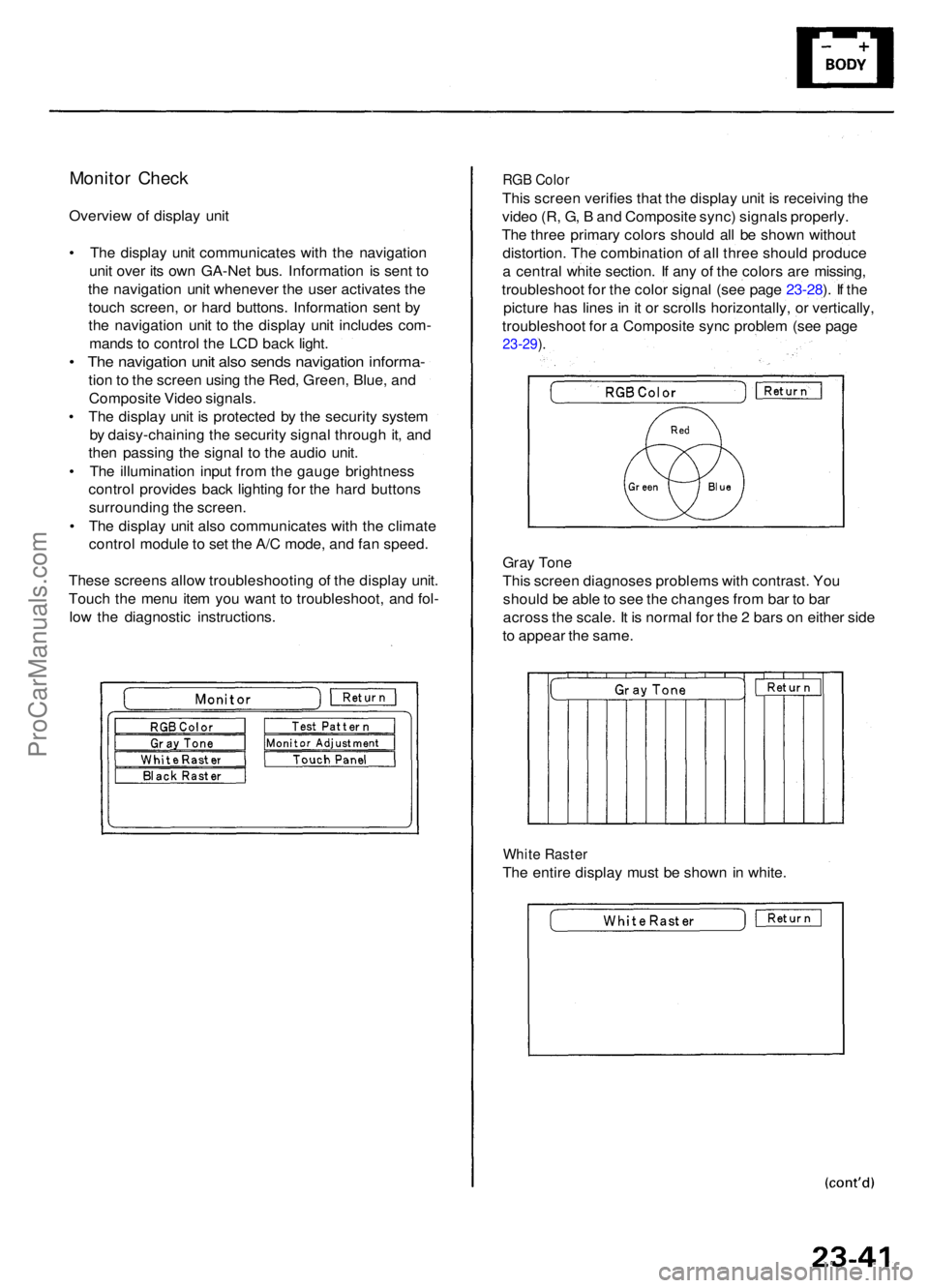
Thes e screen s allo w troubleshootin g o f th e displa y unit .
Touc h th e men u ite m yo u wan t t o troubleshoot , an d fol -
low the diagnosti c instructions .
RGB Colo r
This scree n verifie s tha t th e displa y uni t i s receivin g th e
vide o (R , G , B an d Composit e sync ) signal s properly .
Th e thre e primar y color s shoul d al l b e show n withou t
distortion . Th e combinatio n o f al l thre e shoul d produc e
a centra l whit e section . I f an y o f th e color s ar e missing ,
troubleshoo t fo r th e colo r signa l (se e pag e 23-28 ). I f th e
pictur e ha s line s i n it o r scroll s horizontally , o r vertically ,
troubleshoo t fo r a Composit e syn c proble m (se e pag e
23-29 ).
Gra y Ton e
Thi s scree n diagnose s problem s wit h contrast . Yo u
shoul d b e abl e to se e th e change s fro m ba r t o ba r
acros s th e scale . I t i s norma l fo r th e 2 bar s o n eithe r sid e
t o appea r th e same .
White Raste r
The entir e displa y mus t b e show n i n white .
ProCarManuals.com
Page 267 of 1954

Navigation System
System Diagnosis Mode (cont'd)
Black Raster
The entire display must be shown in black.
Test Pattern
The chart below; shows the colors being used for the
map and menu screens. This is for factory use only. To
check the color signal use the "RGB Color" diagnostic
found under the Monitor Check menu item.
Monitor Adjustment
This allows the navigation display to be centered. Use
the joystick to move the picture up/down or left/right. It
is unlikely that you will ever need to adjust the monitor
position. The "Default" button will reset the display
position to factory specifications.
Touch Panel
The panel touch sensing system consists of 9 horizontal
and 20 vertical infrared beams. Touching the screen
blocks both a horizontal and a vertical beam. Every pos-
sible touch position is shown on this diagnostic screen.
Touching one of these areas should cause its color to
reverse, and sound a "beep". If any areas of the screen
either don't respond, or respond at some other location
when touched, then replace the display unit. The
"Display" diagnostic listed in Unit Check provides an
additional method to determine if one of the infrared
sources or detectors is bad.
NOTE: Direct sunlight can affect this test by falsely trig-
gering the infrared detectors, so perform this diagnostic
inside or in a shaded area.ProCarManuals.com
Page 268 of 1954
Unit Check
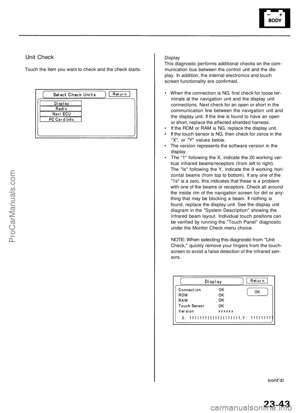
Touch the item you want to check and the check starts.
Display
This diagnostic performs additional checks on the com-
munication bus between the control unit and the dis-
play. In addition, the internal electronics and touch
screen functionality are confirmed.
• When the connection is NG, first check for loose ter-
minals at the navigation unit and the display unit
connections. Next check for an open or short in the
communication line between the navigation unit and
the display unit. If the line is found to have an open
or short, replace the affected shielded harness.
• If the ROM or RAM is NG, replace the display unit.
• If the touch sensor is NG, then check for zeros in the
"X", or "Y" values below.
• The version represents the software version in the
display.
• The "1" following the X, indicate the 20 working ver-
tical infrared beams/receptors (from left to right).
The "Is" following the Y, indicate the 9 working hori-
zontal beams (from top to bottom). If any one of the
"1s" is a zero, this indicates that these is a problem
with one of the beams or receptors. Check all around
the inside rim of the navigation screen for dirt or any-
thing that may be blocking a beam. If nothing is
found, replace the display unit. See the display unit
diagram in the "System Description" showing the
infrared beam layout. Individual touch positions can
be verified by running the "Touch Panel" diagnostic
under the Monitor Check menu choice.
NOTE: When selecting this diagnostic from "Unit
Check," quickly remove your fingers from the touch-
screen to avoid a false detection of the infrared sen-
sors.ProCarManuals.com
Page 269 of 1954
Navigation Syste m
System Diagnosi s Mod e (cont'd )
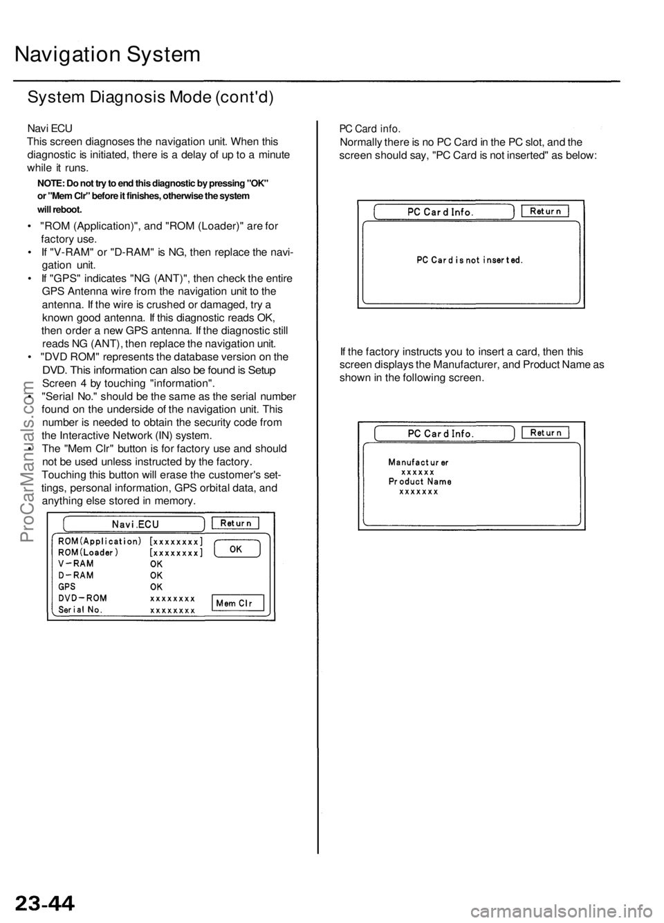
Navi EC U
Thi s scree n diagnose s th e navigatio n unit . Whe n thi s
diagnosti c i s initiated , ther e is a dela y o f u p to a minut e
whil e it runs .
• "RO M (Application)" , an d "RO M (Loader) " ar e fo r
factor y use .
• I f "V-RAM " o r "D-RAM " i s NG , the n replac e th e navi -
gatio n unit .
• I f "GPS " indicate s "N G (ANT)" , the n chec k th e entir e
GP S Antenn a wir e fro m th e navigatio n uni t t o th e
antenna . I f th e wir e is crushe d o r damaged , tr y a
know n goo d antenna . I f thi s diagnosti c read s OK ,
the n orde r a ne w GP S antenna . I f th e diagnosti c stil l
read s N G (ANT) , the n replac e th e navigatio n unit .
• "DV D ROM " represent s th e databas e versio n o n th e
DVD . Thi s informatio n ca n als o b e foun d is Setu p
Scree n 4 by touchin g "information" .
• "Seria l No. " shoul d b e th e sam e a s th e seria l numbe r
foun d o n th e undersid e o f th e navigatio n unit . Thi s
numbe r i s neede d t o obtai n th e securit y cod e fro m
th e Interactiv e Networ k (IN ) system .
• Th e "Me m Clr " butto n is fo r factor y us e an d shoul d
no t b e use d unles s instructe d b y th e factory .
Touchin g thi s butto n wil l eras e th e customer' s set -
tings , persona l information , GP S orbita l data , an d
anythin g els e store d in memory .
PC Car d info .
Normall y ther e is n o P C Car d in th e P C slot , an d th e
scree n shoul d say , "P C Car d is no t inserted " a s below :
I f th e factor y instruct s yo u t o inser t a card , the n thi s
scree n display s th e Manufacturer , an d Produc t Nam e a s
show n in th e followin g screen .
NOTE: Do not try to end this diagnostic by pressing "OK"
or "Mem Clr" before it finishes, otherwise the system
will reboot.
ProCarManuals.com
Page 270 of 1954
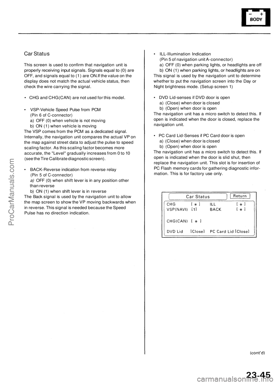
Car Status
This screen is used to confirm that navigation unit is
properly receiving input signals. Signals equal to (0) are
OFF, and signals equal to (1) are ON.If the value on the
display does not match the actual vehicle status, then
check the wire carrying the signal.
• CHG and CHG(CAN) are not used for this model.
• VSP-Vehicle Speed Pulse from PCM
(Pin 6 of C-connector)
a) OFF (0) when vehicle is not moving
b) ON (1) when vehicle is moving
The VSP comes from the PCM as a dedicated signal.
Internally, the navigation unit compares the actual VP on
the map against street data to adjust the pulse to speed
scaling factor. As this scaling factor becomes more
accurate, the "Level" gradually increases from 0 to 10
(see the Tire Calibrate diagnostic screen).
• BACK-Reverse indication from reverse relay
(Pin 5 of C-connector)
a) OFF (0) when shift lever is in any position other
than reverse
b) ON (1) when shift lever is in reverse
The Back signal is used by the navigation unit to allow
the map screen to show the VP moving backwards when
in reverse. This signal is needed because the Speed
Pulse has no direction indication.
• ILL-lllumination Indication
(Pin 5 of navigation unit A-connector)
a) OFF (0) when parking lights, or headlights are off
b) ON (1) when parking lights, or headlights are on
This signal is used by the navigation unit to determine
whether to put the navigation screen into the Day or
Night brightness mode. (Setup screen 1)
• DVD Lid-senses if DVD door is open
a) (Close) when door is closed
b) (Open) when door is open
The navigation unit has a micro switch to detect this. If
open is indicated when the door is closed, replace the
navigation unit.
• PC Card Lid-Senses if PC Card door is open
a) (Close) when door is closed
b) (Open) when door is open
The navigation unit has a micro switch to detect this. If
open is indicated when the door is slid shut, then
replace the navigation unit. This slot is for insertion of
PC Flash memory cards for gathering diagnostic infor-
mation. This is for factory use only.ProCarManuals.com