ACURA RL KA9 1996 Service Repair Manual
Manufacturer: ACURA, Model Year: 1996, Model line: RL KA9, Model: ACURA RL KA9 1996Pages: 1954, PDF Size: 61.44 MB
Page 771 of 1954
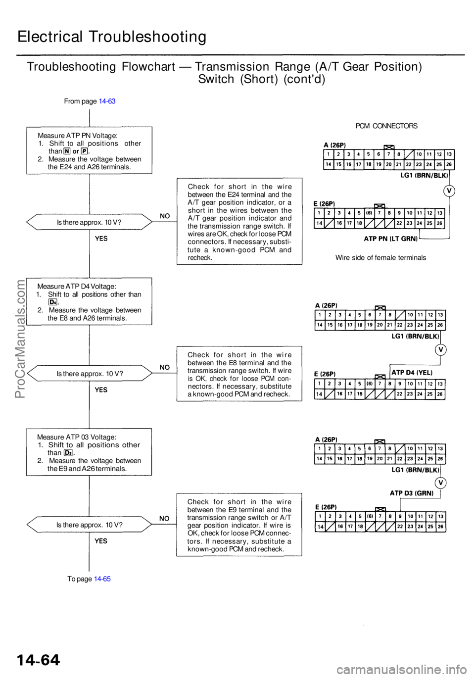
Electrical Troubleshootin g
Troubleshooting Flowchar t — Transmissio n Rang e (A/ T Gea r Position )
Switc h (Short ) (cont'd )
From pag e 14-6 3
I s ther e approx . 1 0 V ?
Measur e AT P D 4 Voltage :1. Shif t t o al l position s othe r tha n
2 . Measur e th e voltag e betwee n
th e E 8 an d A2 6 terminals .
I s ther e approx . 1 0 V ?
Measur e AT P 0 3 Voltage :
1. Shif t t o al l position s othe rthan
2 . Measur e th e voltag e betwee n
the E 9 an d A2 6 terminals .
Is ther e approx . 1 0 V ?
T o pag e 14-6 5 Chec
k fo r shor t i n th e wir e
betwee n th e E2 4 termina l an d th e
A/ T gea r positio n indicator , o r a
shor t i n th e wire s betwee n th e
A/ T gea r positio n indicato r an d
th e transmissio n rang e switch . I f
wire s ar e OK , chec k fo r loos e PC M
connectors . I f necessary , substi -
tut e a known-goo d PC M an d
recheck .
Check fo r shor t i n th e wir e
betwee n th e E 8 termina l an d th e
transmissio n rang e switch . I f wir e
is OK , chec k fo r loos e PC M con -nectors . I f necessary , substitut e
a known-goo d PC M an d recheck .
Chec k fo r shor t i n th e wir e
betwee n th e E 9 termina l an d th e
transmissio n rang e switc h o r A/ T
gea r positio n indicator . I f wir e i s
OK , chec k fo r loos e PC M connec -
tors . I f necessary , substitut e a
known-goo d PC M an d recheck . PC
M CONNECTOR S
Wir e sid e o f femal e terminal s
Measur
e AT P P N Voltage :
1 . Shif t t o al l position s othe r
than
2 . Measur e th e voltag e betwee n
th e E2 4 an d A2 6 terminals .
ProCarManuals.com
Page 772 of 1954
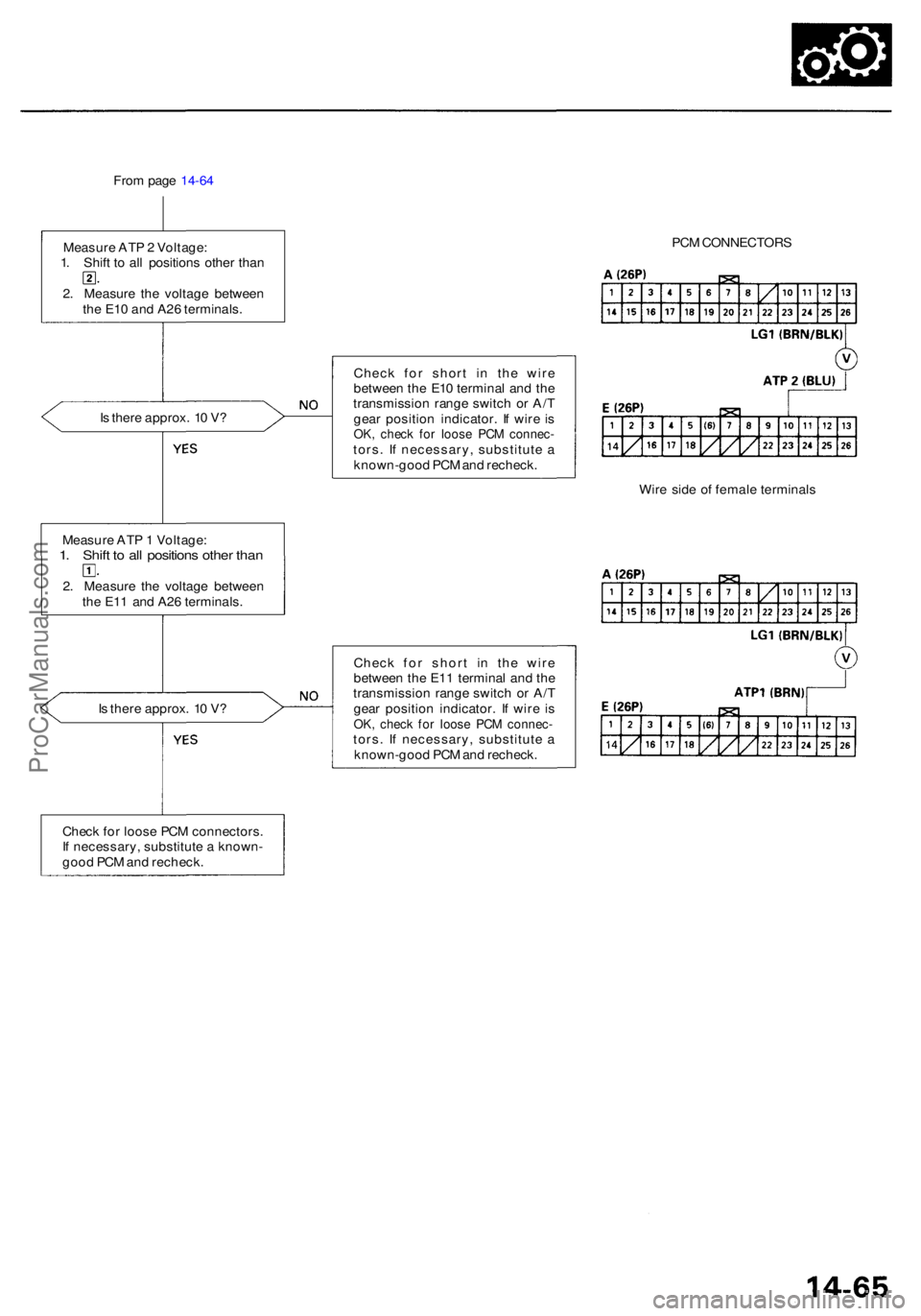
From pag e 14-6 4
I s ther e approx . 1 0 V ? Chec
k fo r shor t i n th e wir e
betwee n th e E1 0 termina l an d th e
transmissio n rang e switc h o r A/ T
gea r positio n indicator . I f wir e i s
OK , chec k fo r loos e PC M connec -tors. I f necessary , substitut e a
known-goo d PC M an d recheck .
Measur e AT P 1 Voltage :
1. Shif t t o al l position s othe r tha n
2. Measur e th e voltag e betwee n
th e E1 1 an d A2 6 terminals .
I s ther e approx . 1 0 V ? Chec
k fo r shor t i n th e wir e
betwee n th e E1 1 termina l an d th e
transmissio n rang e switc h o r A/ T
gea r positio n indicator . I f wir e i s
OK , chec k fo r loos e PC M connec -tors. I f necessary , substitut e a
known-goo d PC M an d recheck .
Chec k fo r loos e PC M connectors .
I f necessary , substitut e a known -
goo d PC M an d recheck . PC
M CONNECTOR S
Wir e sid e o f femal e terminal s
Measur
e AT P 2 Voltage :
1. Shif t t o al l position s othe r tha n
2 . Measur e th e voltag e betwee n
th e E1 0 an d A2 6 terminals .
ProCarManuals.com
Page 773 of 1954
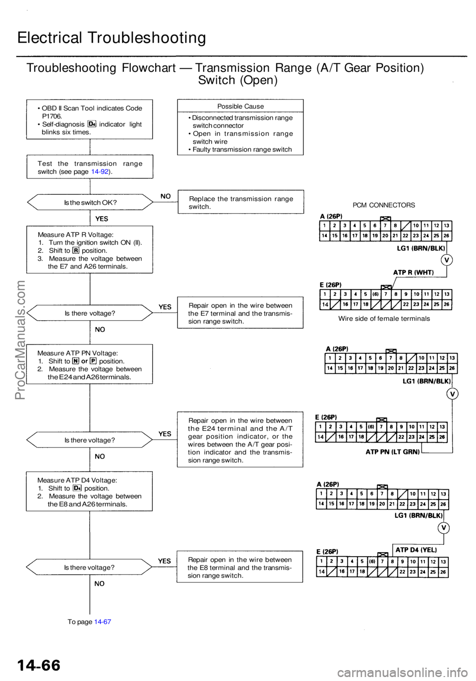
Electrical Troubleshootin g
Troubleshooting Flowchar t — Transmissio n Rang e (A/ T Gea r Position )
Switch (Open )
• OB D II Sca n Too l indicate s Cod eP1706 .• Self-diagnosi s indicato r ligh t
blink s si x times .
Tes t th e transmissio n rang e
switc h (se e pag e 14-92 ).
Is th e switc h OK ?
Measur e AT P R Voltage :
1 . Tur n th e ignitio n switc h O N (II) .
2. Shif t t o position .
3 . Measur e th e voltag e betwee n
th e E 7 an d A2 6 terminals .
I s ther e voltage ?
Measur e AT P P N Voltage :
1. Shif t t o position .
2 . Measur e th e voltag e betwee n
the E2 4 an d A2 6 terminals .
Is ther e voltage ?
Measur e AT P D 4 Voltage :
1. Shif t t o position .
2 . Measur e th e voltag e betwee n
the E 8 an d A2 6 terminals .
Is ther e voltage ?
T o pag e 14-6 7
Possibl e Caus e
• Disconnecte d transmissio n rang e
switc h connecto r
• Ope n i n transmissio n rang e
switc h wir e
• Fault y transmissio n rang e switc h
Replac e th e transmissio n rang e
switch .
Repai r ope n in th e wir e betwee n
th e E 7 termina l an d th e transmis -
sio n rang e switch .
Repai r ope n in th e wir e betwee n
the E2 4 termina l an d th e A/ Tgea r positio n indicator , o r th e
wire s betwee n th e A/ T gea r posi -
tio n indicato r an d th e transmis -
sio n rang e switch .
Repai r ope n in th e wir e betwee n
th e E 8 termina l an d th e transmis -
sio n rang e switch .
PCM CONNECTOR S
Wire sid e o f femal e terminal s
ProCarManuals.com
Page 774 of 1954
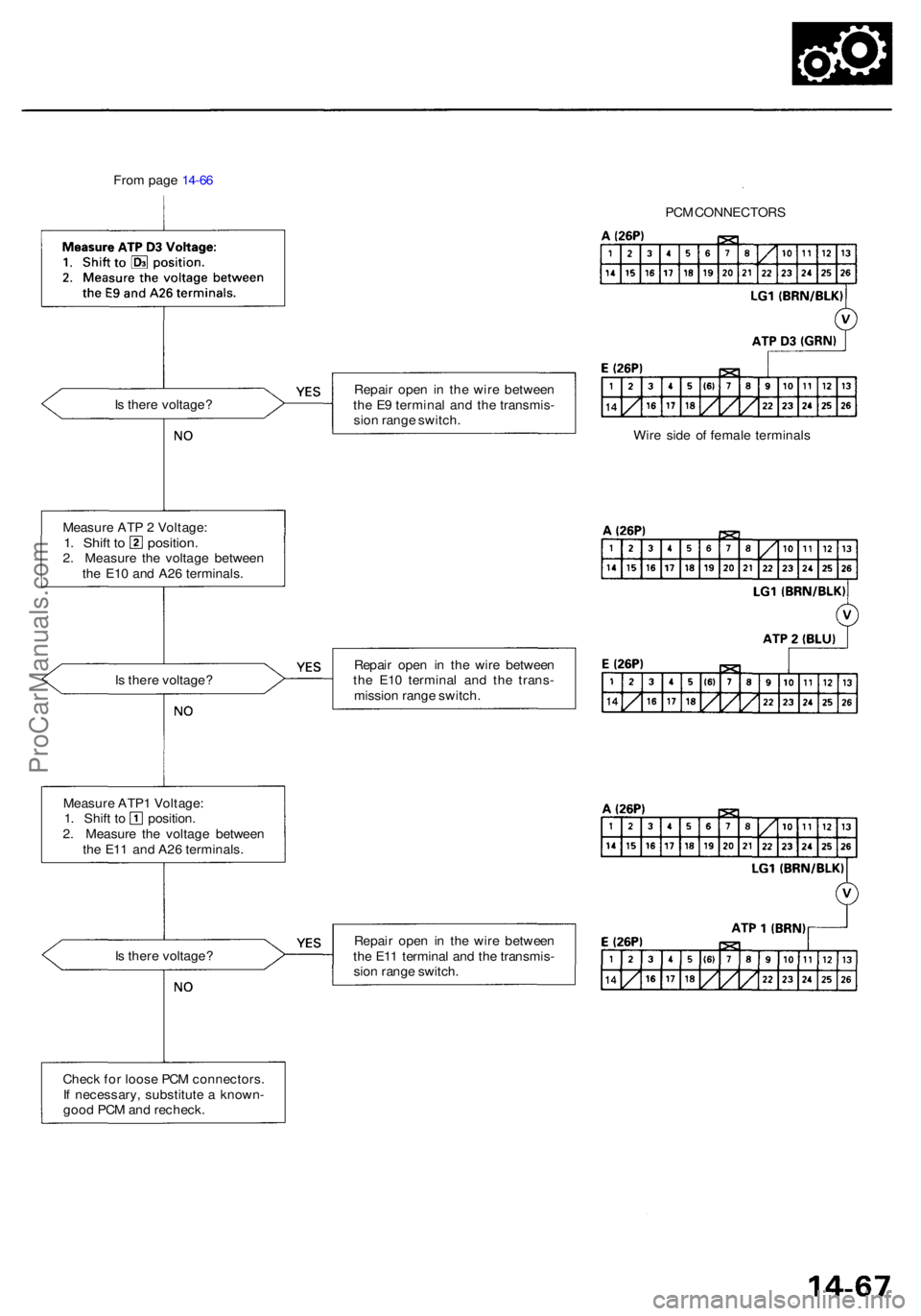
From pag e 14-6 6
I s ther e voltage ? Repai
r ope n i n th e wir e betwee n
th e E 9 termina l an d th e transmis -
sio n rang e switch .
I s ther e voltage ? Repai
r ope n i n th e wir e betwee n
th e E1 0 termina l an d th e trans -
missio n rang e switch .
I s ther e voltage ? Repai
r ope n i n th e wir e betwee n
th e E1 1 termina l an d th e transmis -
sio n rang e switch .
Chec k fo r loos e PC M connectors .
I f necessary , substitut e a known -
goo d PC M an d recheck . PC
M CONNECTOR S
Wir e sid e o f femal e terminal s
Measur e AT P 2 Voltage :
1. Shif t t o position .2. Measur e th e voltag e betwee n
th e E1 0 an d A2 6 terminals .
Measur e ATP 1 Voltage :
1. Shif t t o position .
2 . Measur e th e voltag e betwee n
th e E1 1 an d A2 6 terminals .
ProCarManuals.com
Page 775 of 1954
Electrical Troubleshootin g
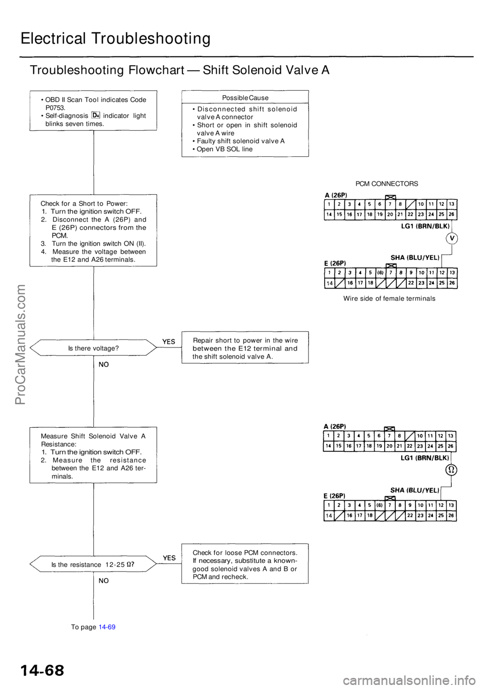
Troubleshooting Flowchar t — Shif t Solenoi d Valv e A
• OB D II Sca n Too l indicate s Cod eP0753 .• Self-diagnosi s indicato r ligh t
blink s seve n times .
Chec k fo r a Shor t t o Power :
1. Tur n th e ignitio n switc h OFF .2. Disconnec t th e A (26P ) an dE (26P ) connector s fro m th ePCM .3. Tur n th e ignitio n switc h O N (II) .
4 . Measur e th e voltag e betwee n
th e E1 2 an d A2 6 terminals .
I s ther e voltage ?
Measur e Shif t Solenoi d Valv e A
Resistance :1. Tur n th e ignitio n switc h OFF .2. Measur e th e resistanc e
betwee n th e E1 2 an d A2 6 ter -
minals .
Is th e resistanc e 12-2 5
T o pag e 14-6 9 Possibl
e Caus e
• Disconnecte d shif t solenoi d
valv e A connecto r
• Shor t o r ope n i n shif t solenoi d
valv e A wir e
• Fault y shif t solenoi d valv e A
• Ope n V B SO L lin e
Repai r shor t t o powe r i n th e wir e
betwee n th e E1 2 termina l an dthe shif t solenoi d valv e A .
Chec k fo r loos e PC M connectors .
If necessary , substitut e a known -good solenoi d valve s A an d B or
PC M an d recheck . PC
M CONNECTOR S
Wir e sid e o f femal e terminal s
ProCarManuals.com
Page 776 of 1954
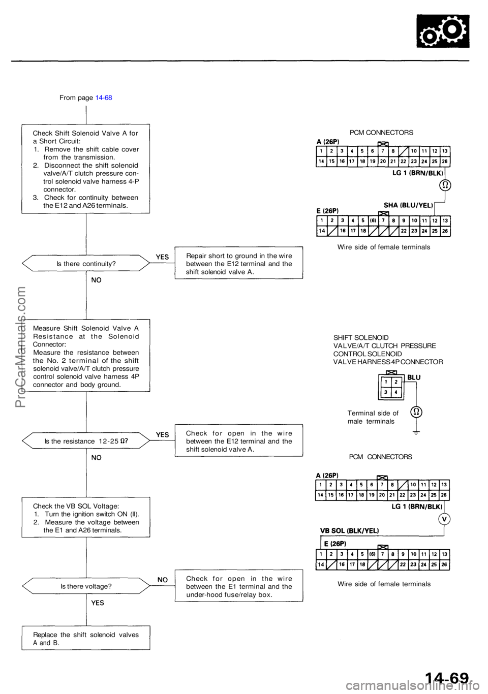
From pag e 14-6 8
Chec k Shif t Solenoi d Valv e A fo r
a Shor t Circuit :
1 . Remov e th e shif t cabl e cove r
fro m th e transmission .
2. Disconnec t th e shif t solenoi dvalve/A/ T clutc h pressur e con -
tro l solenoi d valv e harnes s 4- P
connector .
3. Chec k fo r continuit y betwee nthe E1 2 an d A2 6 terminals .
Is ther e continuity ?
Measur e Shif t Solenoi d Valv e A
Resistanc e a t th e Solenoi d
Connector :
Measur e th e resistanc e betwee n
the No . 2 termina l o f th e shif tsolenoi d valve/A/ T clutc h pressur e
contro l solenoi d valv e harnes s 4 P
connecto r an d bod y ground .
Is th e resistanc e 12-2 5
Chec k th e V B SO L Voltage :
1 . Tur n th e ignitio n switc h O N (II) .
2 . Measur e th e voltag e betwee n
th e E 1 an d A2 6 terminals .
I s ther e voltage ? Repai
r shor t t o groun d in th e wir e
betwee n th e E1 2 termina l an d th e
shif t solenoi d valv e A .
Chec k fo r ope n i n th e wir e
betwee n th e E1 2 termina l an d th e
shif t solenoi d valv e A .
Chec k fo r ope n i n th e wir e
betwee n th e E 1 termina l an d th e
under-hoo d fuse/rela y box . PC
M CONNECTOR S
Wir e sid e o f femal e terminal s
SHIF T SOLENOI D
VALVE/A/ T CLUTC H PRESSUR E
CONTRO L SOLENOI D
VALV E HARNES S 4P CONNECTO R
Termina l sid e o f
mal e terminal s
PC M CONNECTOR S
Wir e sid e o f femal e terminal s
Replac e th e shif t solenoi d valve s
A an d B .
ProCarManuals.com
Page 777 of 1954
Electrical Troubleshootin g
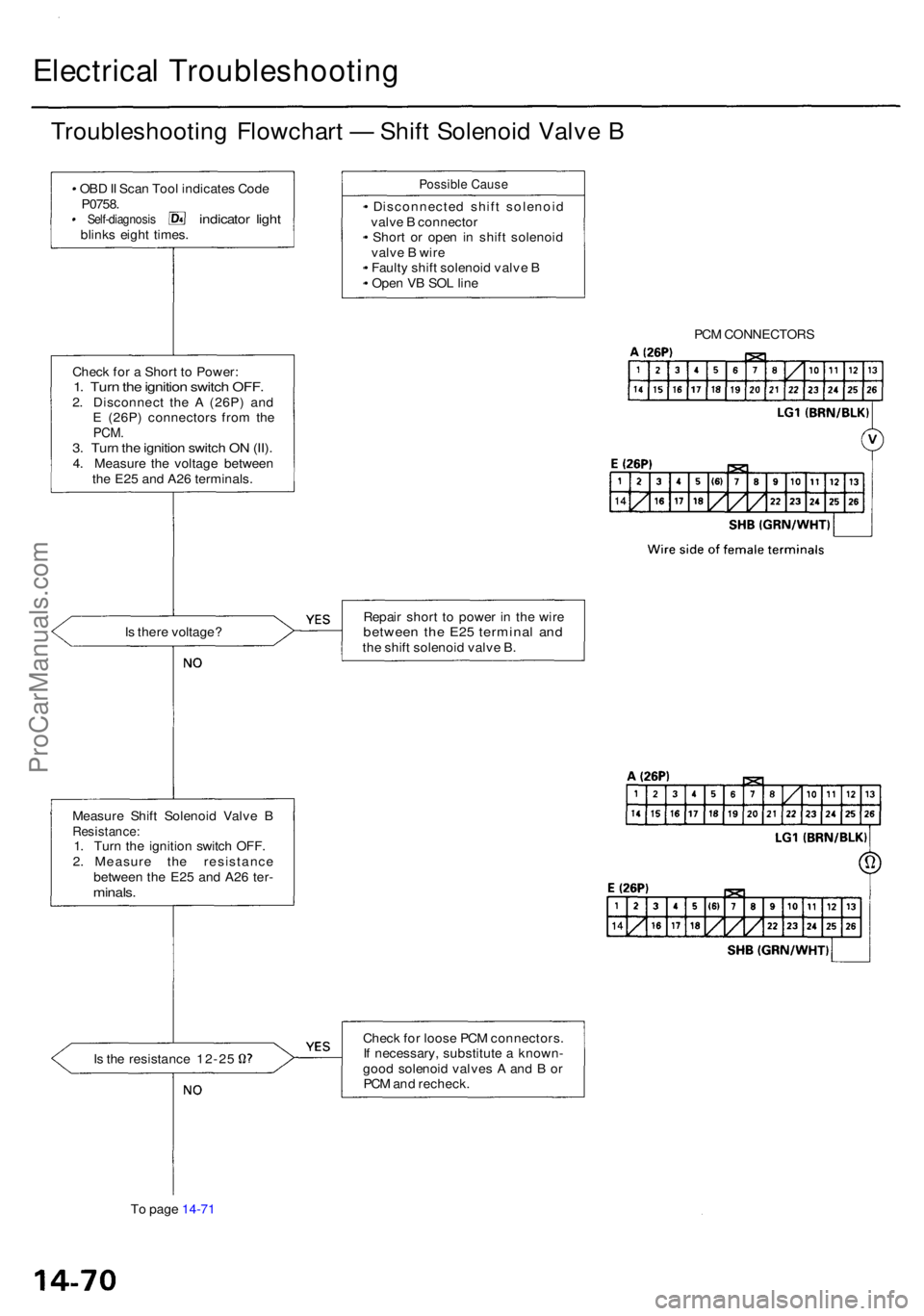
Troubleshooting Flowchar t — Shif t Solenoi d Valv e B
• OB D II Sca n Too l indicate s Cod e
P0758 .
• Self-diagnosi s indicator ligh tblink s eigh t times .
Possibl e Caus e
• Disconnecte d shif t solenoi d
valv e B connecto r
• Shor t o r ope n i n shif t solenoi d
valv e B wir e
• Fault y shif t solenoi d valv e B
• Ope n V B SO L lin e
Chec k fo r a Shor t t o Power :
1. Tur n th e ignitio n switc h OFF .2. Disconnec t th e A (26P ) an d
E (26P ) connector s fro m th e
PCM .3. Tur n th e ignitio n switc h O N (II) .4. Measur e th e voltag e betwee n
th e E2 5 an d A2 6 terminals .
I s ther e voltage ? Repai
r shor t t o powe r i n th e wir e
betwee n th e E2 5 termina l an dthe shif t solenoi d valv e B .
Measur e Shif t Solenoi d Valv e B
Resistance :1. Tur n th e ignitio n switc h OFF .
2 . Measur e th e resistanc e
betwee n th e E2 5 an d A2 6 ter -
minals .
Is th e resistanc e 12-2 5 Chec
k fo r loos e PC M connectors .
I f necessary , substitut e a known -
goo d solenoi d valve s A an d B or
PC M an d recheck .
T o pag e 14-7 1 PC
M CONNECTOR S
ProCarManuals.com
Page 778 of 1954
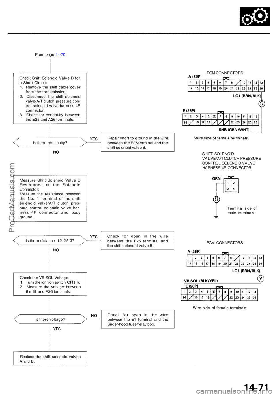
From pag e 14-7 0
Chec k Shif t Solenoi d Valv e B fo r
a Shor t Circuit :
1 . Remov e th e shif t cabl e cove r
fro m th e transmission .
2 . Disconnec t th e shif t solenoi d
valve/A/ T clutc h pressur e con -
tro l solenoi d valv e harnes s 4 P
connector .
3 . Chec k fo r continuit y betwee n
th e E2 5 an d A2 6 terminals .
I s ther e continuity ?
Measur e Shif t Solenoi d Valv e B
Resistanc e a t th e Solenoi d
Connector :
Measur e th e resistanc e betwee n
th e No . 1 termina l o f th e shif t
solenoi d valve/A/ T clutc h pres -
sur e contro l solenoi d valv e har -
nes s 4 P connecto r an d bod y
ground .
Is th e resistanc e 12-2 5
Replac e th e shif t solenoi d valve s
A an d B .
Repai r shor t t o groun d in th e wir ebetwee n th e E2 5 termina l an d th eshif t solenoi d valv e B .
Chec k fo r ope n i n th e wir e
betwee n th e E2 5 termina l an d
th e shif t solenoi d valv e B .
Chec k fo r ope n i n th e wir e
betwee n th e E 1 termina l an d th e
under-hoo d fuse/rela y box . PC
M CONNECTOR S
SHIF T SOLENOI D
VALVE/A/ T CLUTC H PRESSUR E
CONTRO L SOLENOI D VALV E
HARNES S 4 P CONNECTO R
Termina l sid e o f
mal e terminal s
PC M CONNECTOR S
Wir e sid e o f femal e terminal s
Chec
k th e V B SO L Voltage :
1. Tur n th e ignitio n switc h O N (II) .2. Measur e th e voltag e betwee n
th e E l an d A2 6 terminals .
I s ther e voltage ?
ProCarManuals.com
Page 779 of 1954
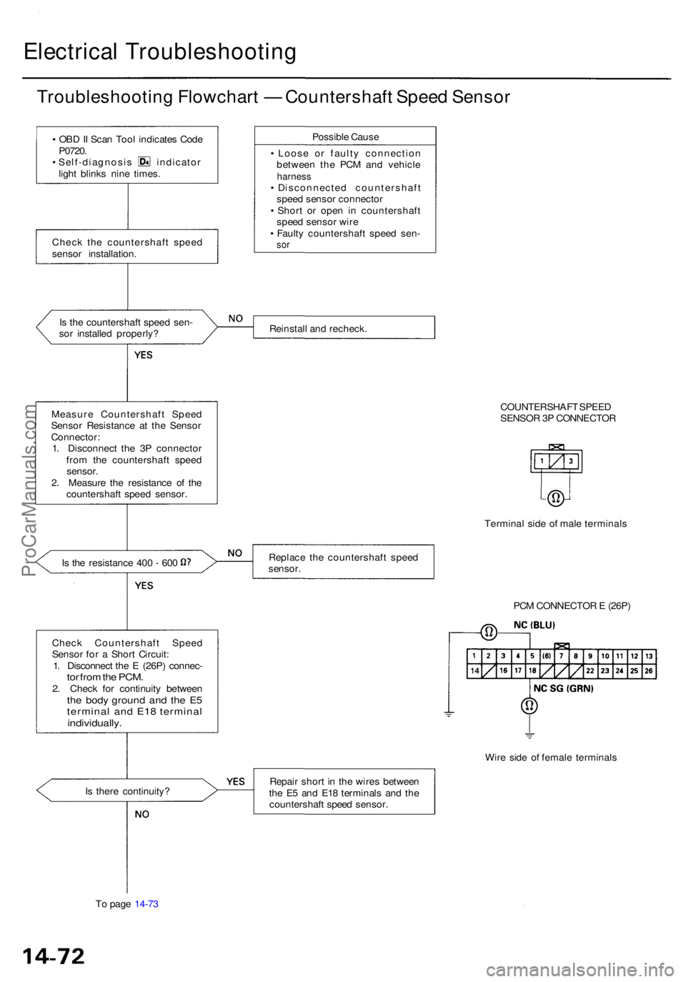
Electrical Troubleshootin g
Troubleshooting Flowchar t — Countershaf t Spee d Senso r
• OB D II Sca n Too l indicate s Cod e
P0720 .
• Self-diagnosi s indicato r
ligh t blink s nin e times .
Chec k th e countershaf t spee d
senso r installation .
I s th e countershaf t spee d sen -
so r installe d properly ?
Measur e Countershaf t Spee d
Senso r Resistanc e a t th e Senso r
Connector :
1 . Disconnec t th e 3 P connecto r
fro m th e countershaf t spee d
sensor .
2 . Measur e th e resistanc e o f th e
countershaf t spee d sensor .
Is th e resistanc e 40 0 - 60 0
Chec k Countershaf t Spee d
Senso r fo r a Shor t Circuit :
1 . Disconnec t th e E (26P ) connec -
tor fro m th e PCM .2. Chec k fo r continuit y betwee nthe bod y groun d an d th e E 5
termina l an d E1 8 termina l
individually .
Possible Caus e
• Loos e o r fault y connectio n
betwee n th e PC M an d vehicl e
harness• Disconnecte d countershaf t
spee d senso r connecto r
• Shor t o r ope n i n countershaf t
spee d senso r wir e
• Fault y countershaf t spee d sen -
sor
Reinstal l an d recheck .
COUNTERSHAFT SPEE D
SENSO R 3 P CONNECTO R
Termina l sid e o f mal e terminal s
Replac e th e countershaf t spee d
sensor .
Wire sid e o f femal e terminal s
I s ther e continuity ? Repai
r shor t i n th e wire s betwee n
th e E 5 an d E1 8 terminal s an d th e
countershaf t spee d sensor .
T o pag e 14-7 3 PC
M CONNECTO R E (26P )
ProCarManuals.com
Page 780 of 1954
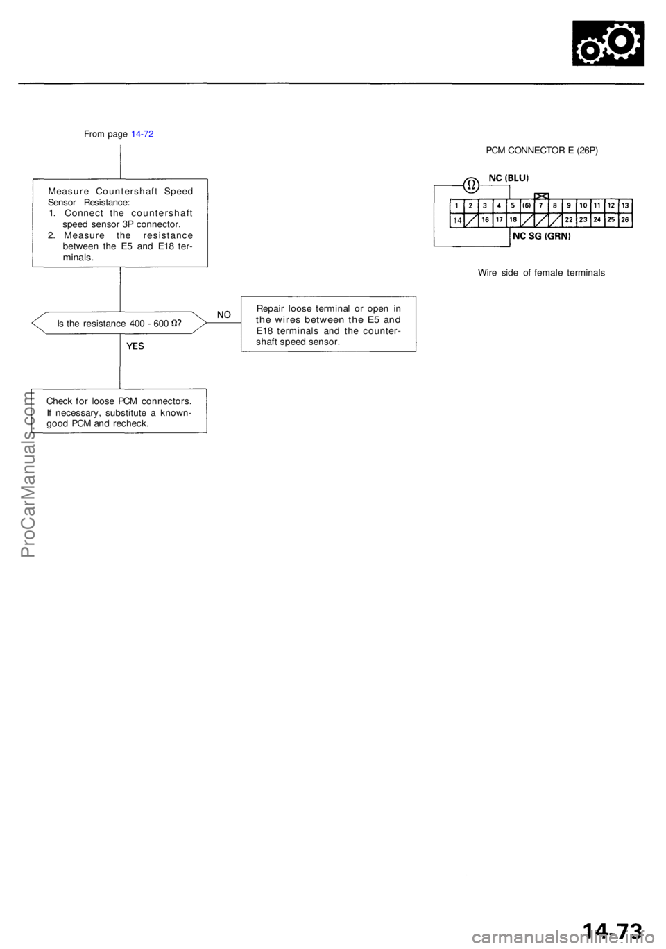
From pag e 14-7 2
PCM CONNECTO R E (26P )
Measur e Countershaf t Spee d
Senso r Resistance :
1 . Connec t th e countershaf t
spee d senso r 3 P connector .
2 . Measur e th e resistanc e
betwee n th e E 5 an d E1 8 ter -
minals .
Wire sid e o f femal e terminal s
Is th e resistanc e 40 0 - 60 0 Repai
r loos e termina l o r ope n i nth e wire s betwee n th e E 5 an dE18 terminal s an d th e counter -
shaf t spee d sensor .
Chec k fo r loos e PC M connectors .
I f necessary , substitut e a known -
goo d PC M an d recheck .
ProCarManuals.com