ACURA TL 1995 Service Repair Manual
Manufacturer: ACURA, Model Year: 1995, Model line: TL, Model: ACURA TL 1995Pages: 1771, PDF Size: 62.49 MB
Page 1761 of 1771
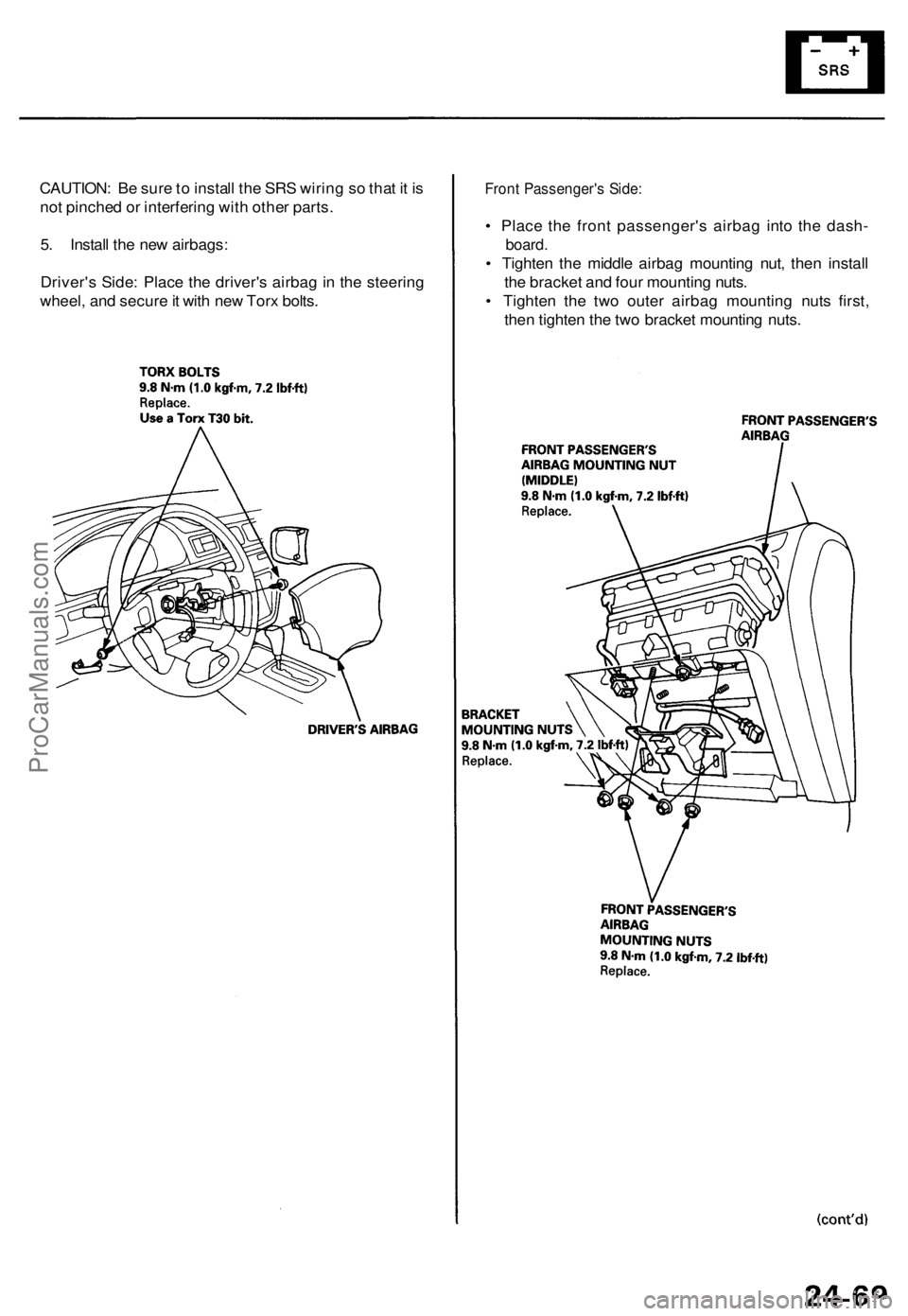
CAUTION: B e sur e to instal l th e SR S wirin g s o tha t i t i s
no t pinche d o r interferin g wit h othe r parts .
5 . Instal l th e ne w airbags :
Driver' s Side : Plac e th e driver' s airba g in th e steerin g
wheel , an d secur e it wit h ne w Tor x bolts .Front Passenger' s Side :
• Plac e th e fron t passenger' s airba g int o th e dash -
board.
• Tighte n th e middl e airba g mountin g nut , the n instal l
th e bracke t an d fou r mountin g nuts .
• Tighte n th e tw o oute r airba g mountin g nut s first ,
the n tighte n th e tw o bracke t mountin g nuts .
ProCarManuals.com
Page 1762 of 1771
Airbag
Replacemen t (cont'd )
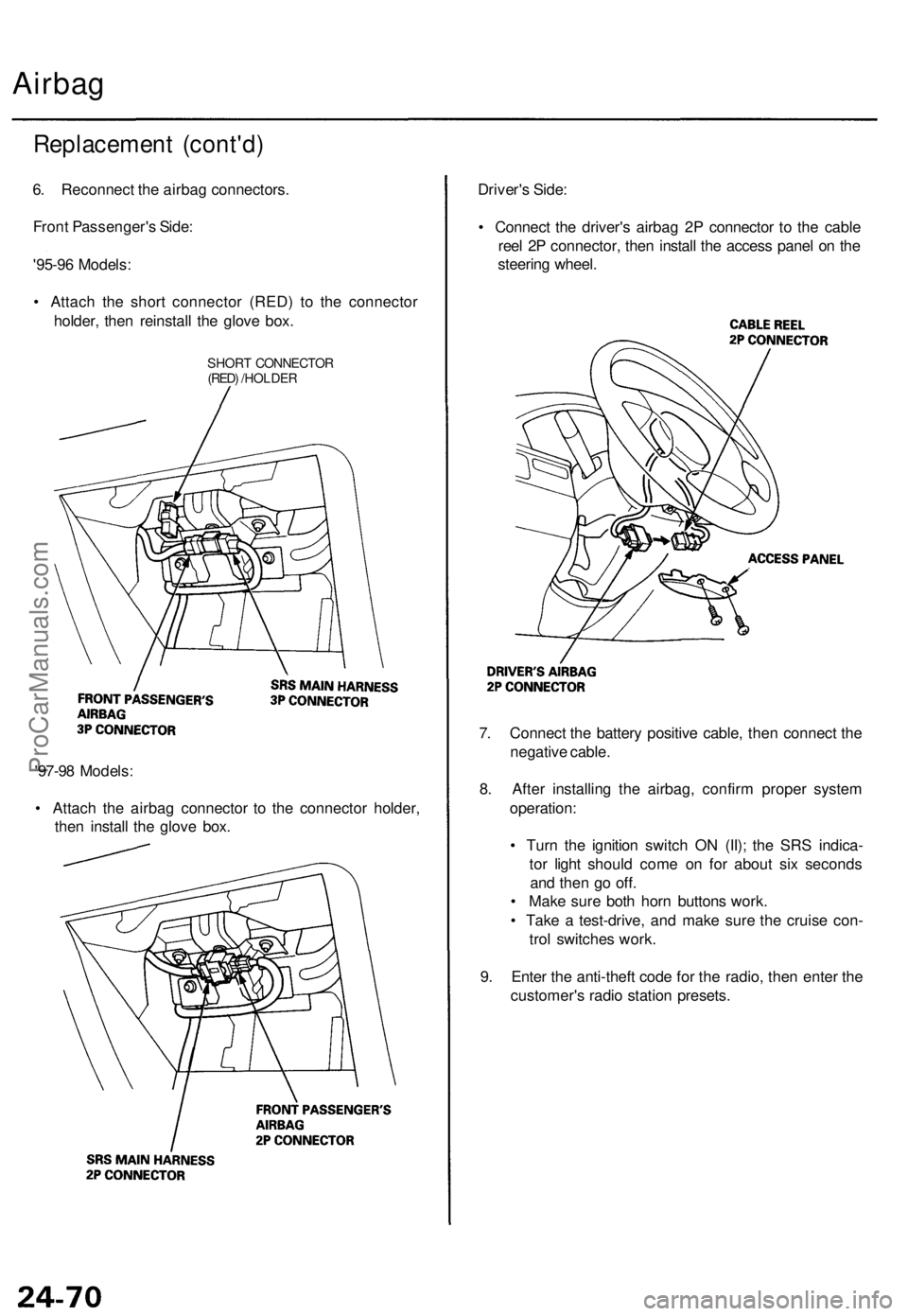
6. Reconnec t th e airba g connectors .
Fron t Passenger' s Side :
'95-9 6 Models :
• Attac h th e shor t connecto r (RED ) t o th e connecto r
holder , the n reinstal l th e glov e box .
SHOR T CONNECTO R(RED) /HOLDE R
'97-98 Models :
• Attac h th e airba g connecto r t o th e connecto r holder ,
the n instal l th e glov e box . Driver'
s Side :
• Connec t th e driver' s airba g 2 P connecto r t o th e cabl e
ree l 2 P connector , the n instal l th e acces s pane l o n th e
steerin g wheel .
7 . Connec t th e batter y positiv e cable , the n connec t th e
negativ e cable .
8 . Afte r installin g th e airbag , confir m prope r syste m
operation :
• Tur n th e ignitio n switc h O N (II) ; th e SR S indica -
to r ligh t shoul d com e o n fo r abou t si x second s
an d the n g o off .
• Mak e sur e bot h hor n button s work .
• Tak e a test-drive , an d mak e sur e th e cruis e con -
tro l switche s work .
9 . Ente r th e anti-thef t cod e fo r th e radio , the n ente r th e
customer' s radi o statio n presets .
ProCarManuals.com
Page 1763 of 1771
Disposal
Before scrappin g an y airbag s (includin g thos e i n a whol e
vehicl e t o b e scrapped) , th e airbag s mus t b e deployed . I f
th e vehicl e is stil l withi n th e warrant y period , befor e yo u
deplo y th e airbags , th e Acur a Distric t Technica l Manage r
mus t giv e approva l and/o r specia l instructions . Onl y afte r
th e airbag s hav e bee n deploye d (a s th e resul t o f vehicl e
collision , fo r example) , ca n the y b e scrapped . I f th e
airbag s appea r intac t (no t deployed) , trea t the m wit h
extrem e caution . Follo w thi s procedure :
Deployin g th e Airbags : In-vehicl e
NOTE : I f a n SR S vehicl e is t o b e entirel y scrapped , it s air -
bag s shoul d b e deploye d whil e stil l i n th e vehicle . Th e
airbag s shoul d no t b e considere d a s salvageabl e part s
an d shoul d neve r b e installe d in anothe r vehicle .
Confir m tha t eac h airba g assembl y i s
securel y mounted ; otherwise , sever e persona l injur y
coul d resul t fro m deployment .
1 . Mak e sur e yo u hav e th e anti-thef t cod e fo r th e
radio , the n writ e dow n th e frequencie s fo r th e
radio' s prese t buttons .
2 . Disconnec t th e batter y negativ e cable , the n discon -
nec t th e positiv e cable .
3. Confir m tha t th e specia l too l i s functionin g properl y
by followin g th e chec k procedur e o n th e labe l o n
th e too l o r th e procedur e o n pag e 24-72 .
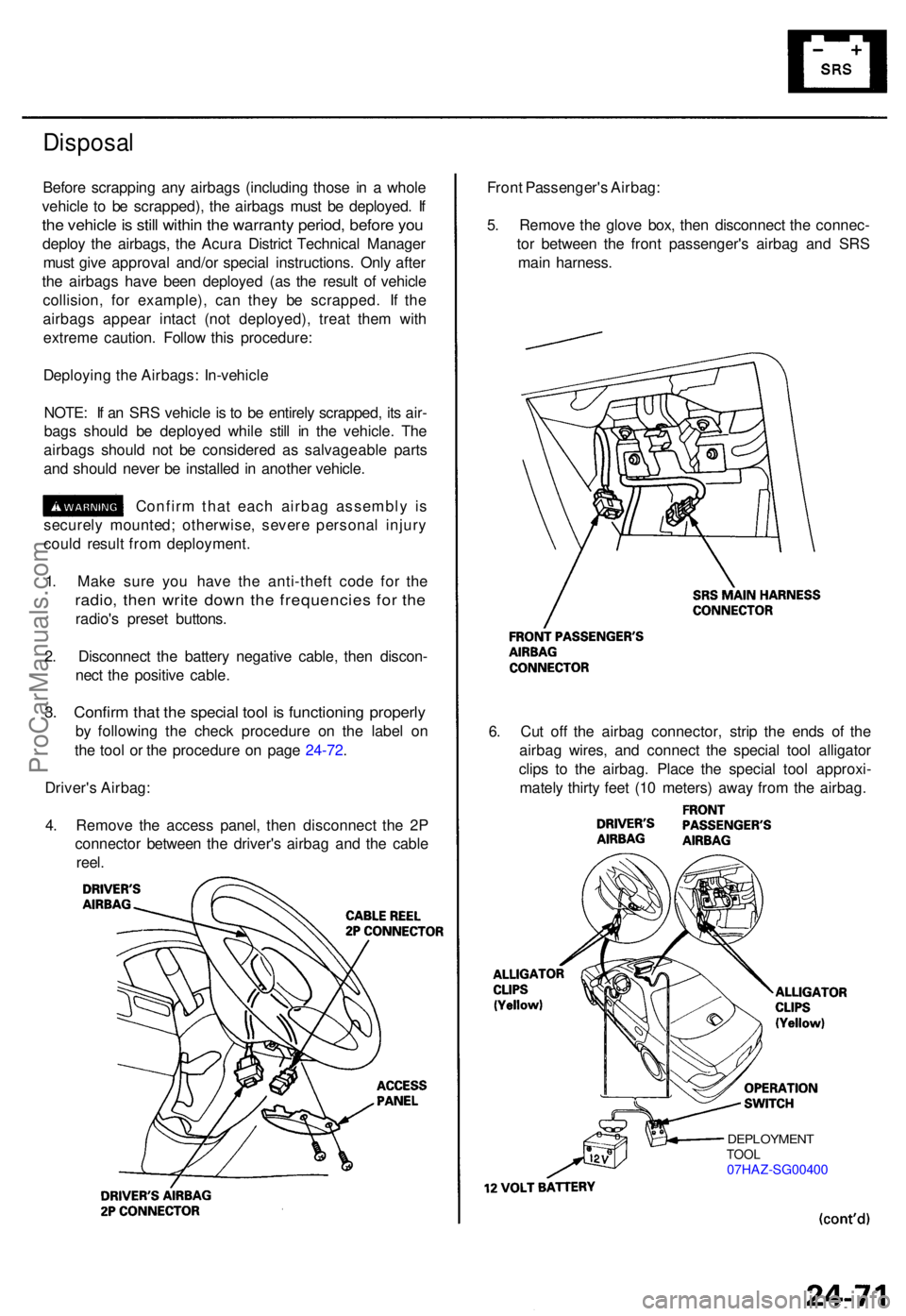
Driver' s Airbag :
4 . Remov e th e acces s panel , the n disconnec t th e 2 P
connecto r betwee n th e driver' s airba g an d th e cabl e
reel . Fron
t Passenger' s Airbag :
5 . Remov e th e glov e box , the n disconnec t th e connec -
to r betwee n th e fron t passenger' s airba g an d SR S
mai n harness .
6 . Cu t of f th e airba g connector , stri p th e end s o f th e
airba g wires , an d connec t th e specia l too l alligato r
clip s t o th e airbag . Plac e th e specia l too l approxi -
matel y thirt y fee t (1 0 meters ) awa y fro m th e airbag .
DEPLOYMEN TTOOL07HAZ-SG0040 0
ProCarManuals.com
Page 1764 of 1771
Airbag
Disposa l (cont'd )
7. Connec t a 1 2 vol t batter y t o th e tool :
• I f th e gree n ligh t o n th e too l come s on , th e air -
ba g ignite r circui t i s defectiv e an d canno t deplo y
th e airbag . G o t o Damage d Airba g Specia l
Procedure .
• I f th e re d ligh t o n th e too l come s on , th e airba g i s
read y t o b e deployed .
8 . Pus h th e tool' s deploymen t switch . Th e airba g
shoul d deplo y (deploymen t i s bot h highl y audibl e
an d visibl e a lou d nois e an d rapi d inflatio n o f th e
bag , followe d b y slo w deflation) .
• I f audible/visibl e deploymen t happens , an d th e
gree n ligh t o n th e too l come s on , continu e wit h
this procedure .
• I f th e airba g doesn' t deploy , ye t th e gree n ligh t
come s ON , it s ignite r i s defective . G o t o Dam -
age d Airba g Specia l Procedure .
• Durin g deployment , th e airba g ca n becom e ho t
enoug h t o bur n you . Wai t thirt y minute s afte r
deploymen t befor e touchin g th e airbag .
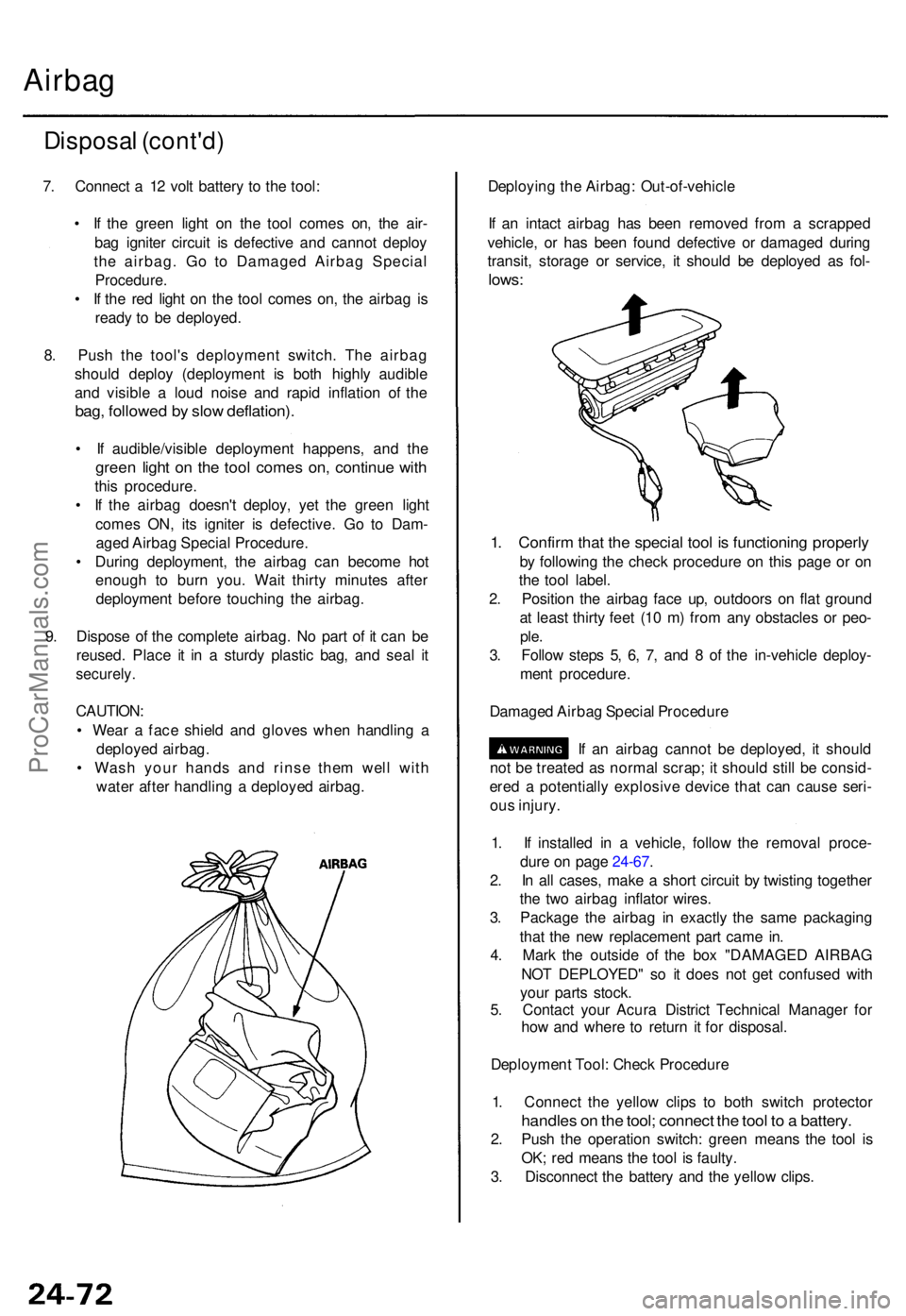
9 . Dispos e o f th e complet e airbag . N o par t o f i t ca n b e
reused . Plac e i t i n a sturd y plasti c bag , an d sea l i t
securely .
CAUTION :
• Wea r a fac e shiel d an d glove s whe n handlin g a
deploye d airbag .
• Was h you r hand s an d rins e the m wel l wit h
wate r afte r handlin g a deploye d airbag . Deployin
g th e Airbag : Out-of-vehicl e
I f a n intac t airba g ha s bee n remove d fro m a scrappe d
vehicle , o r ha s bee n foun d defectiv e o r damage d durin g
transit , storag e o r service , i t shoul d b e deploye d a s fol -
lows :
1. Confir m tha t th e specia l too l i s functionin g properl y
by followin g th e chec k procedur e o n thi s pag e o r o n
th e too l label .
2 . Positio n th e airba g fac e up , outdoor s o n fla t groun d
a t leas t thirt y fee t (1 0 m ) fro m an y obstacle s o r peo -
ple.
3. Follo w step s 5 , 6 , 7 , an d 8 of th e in-vehicl e deploy -
men t procedure .
Damage d Airba g Specia l Procedur e
I f a n airba g canno t b e deployed , i t shoul d
no t b e treate d a s norma l scrap ; i t shoul d stil l b e consid -
ere d a potentiall y explosiv e devic e tha t ca n caus e seri -
ou s injury .
1 . I f installe d i n a vehicle , follo w th e remova l proce -
dur e o n pag e 24-67 .
2 . I n al l cases , mak e a shor t circui t b y twistin g togethe r
th e tw o airba g inflato r wires .
3 . Packag e th e airba g i n exactl y th e sam e packagin g
tha t th e ne w replacemen t par t cam e in .
4 . Mar k th e outsid e o f th e bo x "DAMAGE D AIRBA G
NO T DEPLOYED " s o i t doe s no t ge t confuse d wit h
you r part s stock .
5 . Contac t you r Acur a Distric t Technica l Manage r fo r
ho w an d wher e t o retur n i t fo r disposal .
Deploymen t Tool : Chec k Procedur e
1 . Connec t th e yello w clip s t o bot h switc h protecto r
handles o n th e tool ; connec t th e too l t o a battery .
2. Pus h th e operatio n switch : gree n mean s th e too l i s
OK ; re d mean s th e too l i s faulty .
3 . Disconnec t th e batter y an d th e yello w clips .
ProCarManuals.com
Page 1765 of 1771
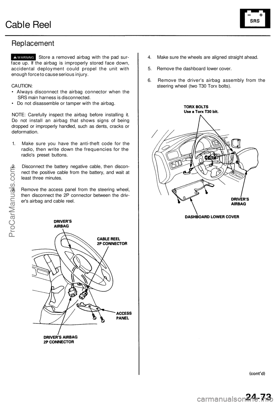
Cable Reel
Replacement
Store a remove d airba g wit h th e pa d sur -
fac e up . I f th e airba g i s improperl y store d fac e down ,
accidenta l deploymen t coul d prope l th e uni t wit h
enoug h forc e to caus e seriou s injury .
CAUTION :
• Alway s disconnec t th e airba g connecto r whe n th e
SR S mai n harnes s is disconnected .
• D o no t disassembl e o r tampe r wit h th e airbag .
NOTE : Carefull y inspec t th e airba g befor e installin g it .
D o no t instal l a n airba g tha t show s sign s o f bein g
droppe d o r improperl y handled , suc h a s dents , crack s o r
deformation .
1. Mak e sur e yo u hav e th e anti-thef t cod e fo r th e
radio , the n writ e dow n th e frequencie s fo r th e
radio' s prese t buttons .
2 . Disconnec t th e batter y negativ e cable , the n discon -
nec t th e positiv e cabl e fro m th e battery , an d wai t a t
leas t thre e minutes .
3 . Remov e th e acces s pane l fro m th e steerin g wheel ,
the n disconnec t th e 2 P connecto r betwee n th e driv -
er' s airba g an d cabl e reel . 4
. Mak e sur e th e wheel s ar e aligne d straigh t ahead .
5 . Remov e th e dashboar d lowe r cover .
6 . Remov e th e driver' s airba g assembl y fro m th e
steerin g whee l (tw o T3 0 Tor x bolts) .
ProCarManuals.com
Page 1766 of 1771
Cable Ree l
Replacemen t (cont'd )
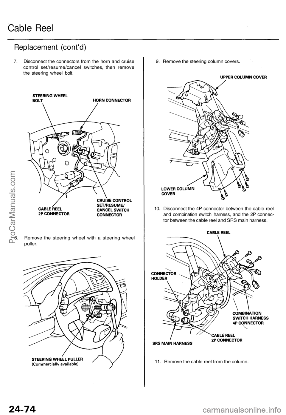
7. Disconnec t th e connector s fro m th e hor n an d cruis e
contro l set/resume/cance l switches , the n remov e
th e steerin g whee l bolt .
8 . Remov e th e steerin g whee l wit h a steerin g whee l
puller.
9. Remov e th e steerin g colum n covers .
10 . Disconnec t th e 4 P connecto r betwee n th e cabl e ree l
an d combinatio n switc h harness , an d th e 2 P connec -
to r betwee n th e cabl e ree l an d SR S mai n harness .
11 . Remov e th e cabl e ree l fro m th e column .
ProCarManuals.com
Page 1767 of 1771
NOTE:
• Befor e installin g th e steerin g wheel , th e fron t
wheel s shoul d b e aligne d straigh t ahead .
• B e sur e t o instal l th e harnes s wire s s o tha t the y
are no t pinche d o r interferin g wit h othe r parts .
• Afte r reassembly , confir m tha t th e wheel s ar e
stil l turne d straigh t ahea d an d tha t th e steerin g
whee l spok e angl e i s correc t (roa d test) . I f mino r
spok e angl e adjustmen t i s necessary , d o s o onl y
b y adjustin g th e tie-rods , no t b y removin g an d
repositionin g th e steerin g wheel .
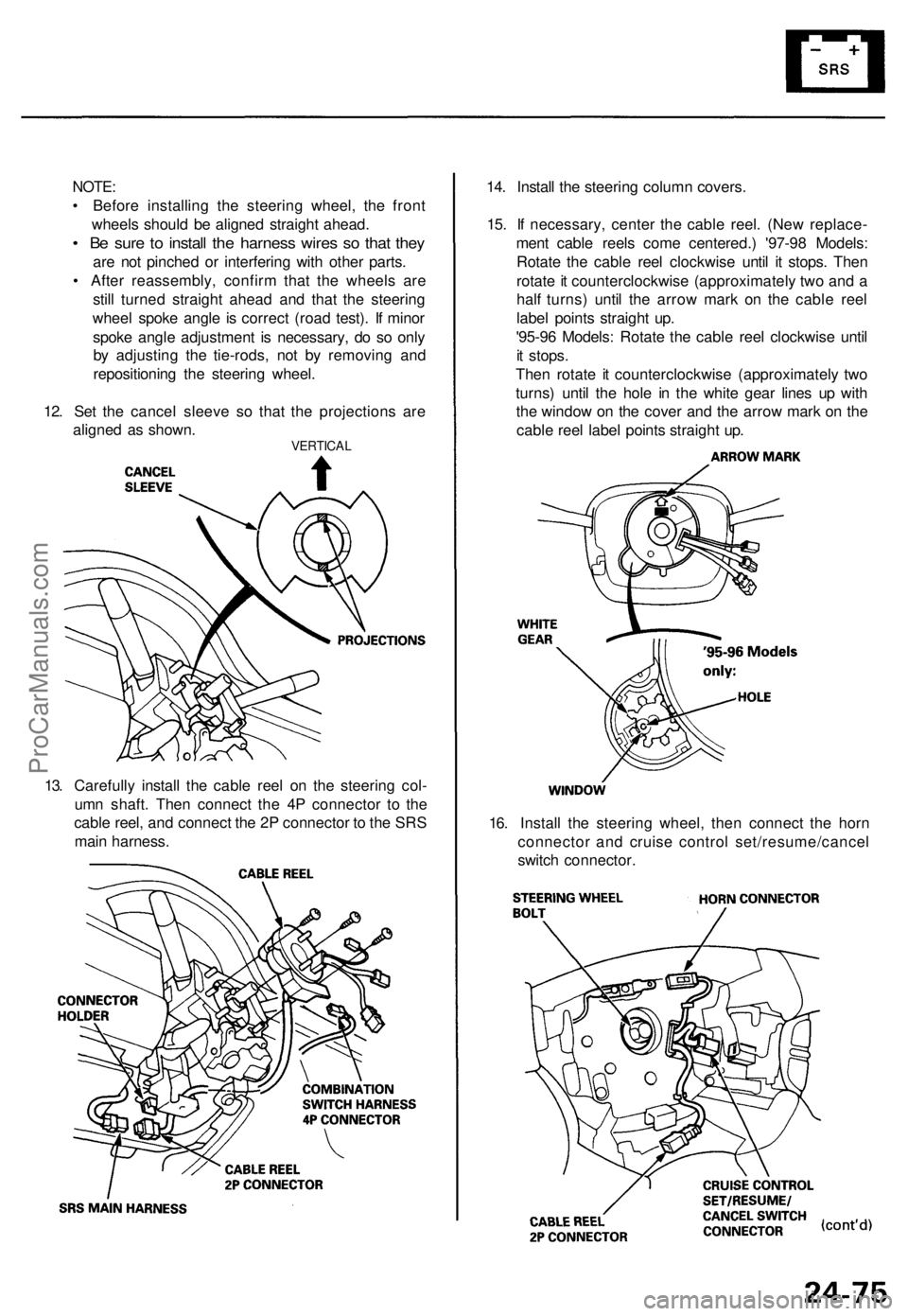
12 . Se t th e cance l sleev e s o tha t th e projection s ar e
aligne d a s shown .
VERTICA L
14. Instal l th e steerin g colum n covers .
15 . I f necessary , cente r th e cabl e reel . (Ne w replace -
men t cabl e reel s com e centered. ) '97-9 8 Models :
Rotat e th e cabl e ree l clockwis e unti l i t stops . The n
rotat e it counterclockwis e (approximatel y tw o an d a
hal f turns ) unti l th e arro w mar k o n th e cabl e ree l
labe l point s straigh t up .
'95-9 6 Models : Rotat e th e cabl e ree l clockwis e unti l
i t stops .
The n rotat e i t counterclockwis e (approximatel y tw o
turns ) unti l th e hol e i n th e whit e gea r line s u p wit h
th e windo w o n th e cove r an d th e arro w mar k o n th e
cabl e ree l labe l point s straigh t up .
16 . Instal l th e steerin g wheel , the n connec t th e hor n
connecto r an d cruis e contro l set/resume/cance l
switc h connector .
13
. Carefull y instal l th e cabl e ree l o n th e steerin g col -
um n shaft . The n connec t th e 4 P connecto r t o th e
cabl e reel , an d connec t th e 2 P connecto r t o th e SR S
mai n harness .
ProCarManuals.com
Page 1768 of 1771
Cable Ree l
Replacemen t (cont'd )
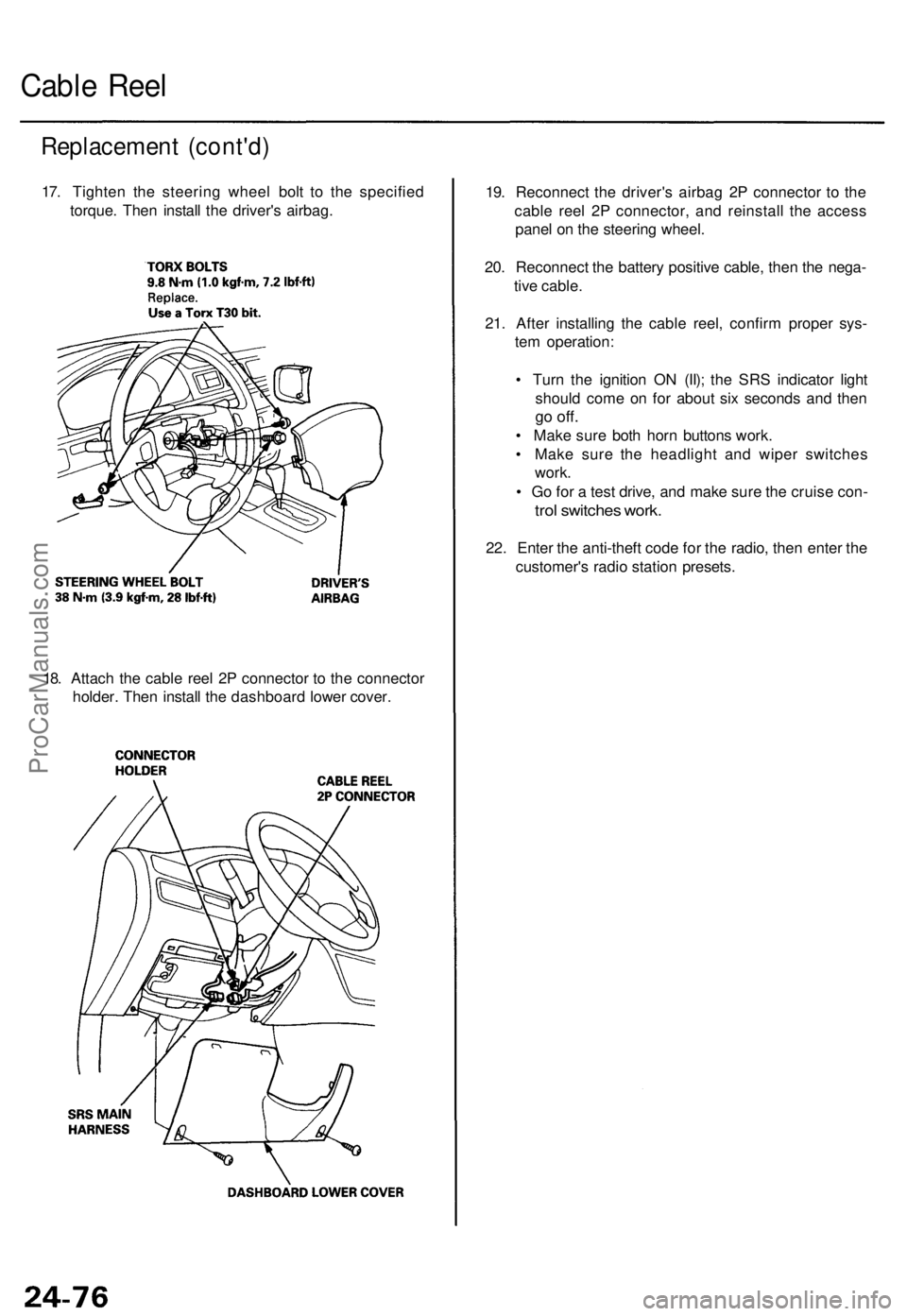
17. Tighte n th e steerin g whee l bol t t o th e specifie d
torque . The n instal l th e driver' s airbag .
18 . Attac h th e cabl e ree l 2 P connecto r t o th e connecto r
holder . The n instal l th e dashboar d lowe r cover . 19
. Reconnec t th e driver' s airba g 2 P connecto r t o th e
cabl e ree l 2 P connector , an d reinstal l th e acces s
pane l o n th e steerin g wheel .
20 . Reconnec t th e batter y positiv e cable , the n th e nega -
tiv e cable .
21 . Afte r installin g th e cabl e reel , confir m prope r sys -
te m operation :
• Tur n th e ignitio n O N (II) ; th e SR S indicato r ligh t
shoul d com e o n fo r abou t si x second s an d the n
go off .
• Mak e sur e bot h hor n button s work .
• Mak e sur e th e headligh t an d wipe r switche s
work .
• G o fo r a tes t drive , an d mak e sur e th e cruis e con -
trol switche s work .
22. Ente r th e anti-thef t cod e fo r th e radio , the n ente r th e
customer' s radi o statio n presets .
ProCarManuals.com
Page 1769 of 1771
SRS Uni t
Replacemen t
CAUTION:
• Durin g installatio n o r replacement , d o no t bum p
(impac t wrench , hamme r etc. ) th e are a nea r th e SR S
unit .
• D o no t damag e th e SR S uni t terminal s o r connec -
tors .
• D o no t disassembl e th e SR S unit ; i t ha s n o service -
abl e parts .
• Stor e th e SR S uni t i n a clean , dr y area .
• D o no t us e an y SR S uni t whic h ha s bee n subjecte d
t o wate r damag e o r show s sign s o f bein g droppe d o r
improperl y handled , suc h a s dents , crack s o r defor -
mation .
1 . Mak e sur e yo u hav e th e anti-thef t cod e fo r th e
radio , the n writ e dow n th e frequencie s fo r th e
radio' s prese t buttons .
2 . Disconnec t th e batter y negativ e cable , the n discon -
nec t th e positiv e cabl e fro m th e battery , an d wai t a t
leas t thre e minutes .
3 . Disconnec t th e airba g connectors .
Driver' s Side :
• Remov e th e acces s pane l fro m th e steerin g wheel ,
the n disconnec t th e 2 P connecto r betwee n th e driver' s
airba g an d cabl e ree l (se e pag e 24-12 ).
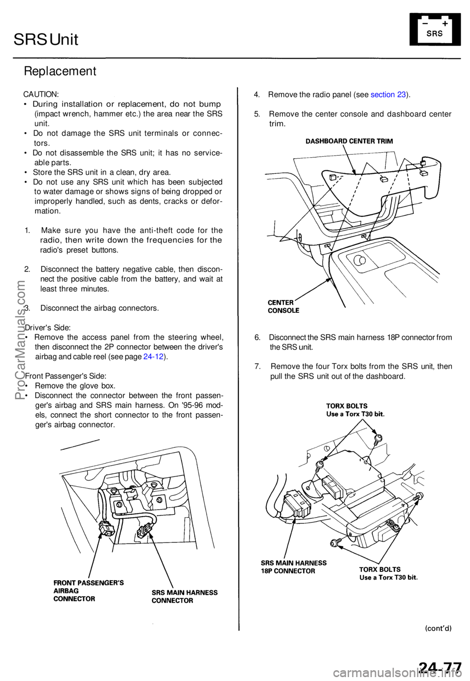
Fron t Passenger' s Side :
• Remov e th e glov e box .
• Disconnec t th e connecto r betwee n th e fron t passen -
ger' s airba g an d SR S mai n harness . O n '95-9 6 mod -
els , connec t th e shor t connecto r t o th e fron t passen -
ger' s airba g connector . 4
. Remov e th e radi o pane l (se e sectio n 23 ).
5 . Remov e th e cente r consol e an d dashboar d cente r
trim.
6. Disconnec t th e SR S mai n harnes s 18 P connecto r fro m
the SR S unit .
7. Remov e th e fou r Tor x bolt s fro m th e SR S unit , the n
pul l th e SR S uni t ou t o f th e dashboard .
ProCarManuals.com
Page 1770 of 1771
SRS Uni t
Replacemen t (cont'd )
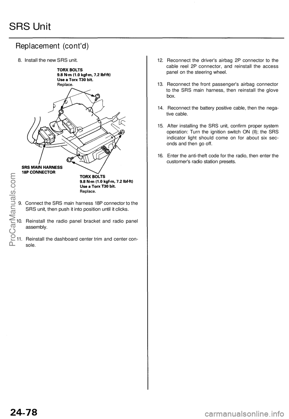
8. Instal l th e ne w SR S unit .
9. Connec t th e SR S mai n harnes s 18 P connecto r t o th e
SR S unit , the n pus h it int o positio n unti l i t clicks .
10. Reinstal l th e radi o pane l bracke t an d radi o pane l
assembly .
11. Reinstal l th e dashboar d cente r tri m an d cente r con -
sole.
12. Reconnec t th e driver' s airba g 2 P connecto r t o th e
cabl e ree l 2 P connector , an d reinstal l th e acces s
pane l o n th e steerin g wheel .
13 . Reconnec t th e fron t passenger' s airba g connecto r
t o th e SR S mai n harness , the n reinstal l th e glov e
box.
14. Reconnec t th e batter y positiv e cable , the n th e nega -
tiv e cable .
15 . Afte r installin g th e SR S unit , confir m prope r syste m
operation : Tur n th e ignitio n switc h O N (II) ; th e SR S
indicato r ligh t shoul d com e o n fo r abou t si x sec -
ond s an d the n g o off .
16 . Ente r th e anti-theft code fo r th e radio , the n ente r th e
customer' s radi o statio n presets .
ProCarManuals.com