tow ACURA TL 1995 Service User Guide
[x] Cancel search | Manufacturer: ACURA, Model Year: 1995, Model line: TL, Model: ACURA TL 1995Pages: 1771, PDF Size: 62.49 MB
Page 104 of 1771

Main Bearing s
Clearanc eSelection
1.
2 .
3.
4 .
5.
6.
7 .
8 .
T o chec k mai n bearing-to-journa l oi l clearance ,
remov e th e mai n cap s an d bearin g halves .
Clea n eac h mai n journa l an d bearin g hal f wit h a
clea n sho p towel .
Plac e on e stri p o f plastigag e acros s eac h mai n jour -
nal.
NOTE : I f th e engin e i s stil l i n th e ca r whe n yo u bol t
th e mai n cap dow n t o chec k clearance , th e weigh t
o f th e crankshaf t an d flywhee l wil l flatte n th e plasti -
gag e furthe r tha n jus t th e torqu e o n th e ca p bolts ,
an d giv e yo u a n incorrec t reading . Fo r a n accurat e
reading , suppor t th e crankshaf t wit h a jac k unde r
th e counterweight s an d chec k onl y on e bearin g a t a
time .
Reinstal l th e bearing s an d caps , the n torqu e th e 9
m m ca p bolt s t o 3 9 N- m (4. 0 kgf-m , 2 9 Ibf-ft) . Torqu e
the 1 1 m m ca p bolt s to 7 6 N- m (7. 8 kgf-m , 5 7 Ibf-ft) .
Torqu e th e sid e bolt s t o 4 9 N- m (5. 0 kgf-m , 3 6 Ibf-ft) .
Remov e th e cap s an d bearings , an d measur e th e
wides t par t o f th e plastigage .
Mai n Bearing-to-Journa l Oi l Clearance :
Standar d (New) : 0.02 0 - 0.04 4 m m
(0.000 8 - 0.001 7 in )
Servic e Limit : 0.0 5 m m (0.00 2 in )
PLASTIGAG E STRI P
If th e plastigag e measure s to o wid e o r to o narrow ,
remov e th e crankshaft , an d remov e th e uppe r hal f
o f th e bearing . Instal l a new , complet e bearin g wit h
th e sam e colo r cod e (selec t th e colo r a s show n i n
th e righ t colum n o f thi s page) , an d rechec k th e
clearance .
CAUTION: D o no t file , shim , o r scrap e th e bearing s
o r th e cap s t o adjus t clearance .
I f th e plastigag e show s th e clearanc e i s stil l incor -
rect , tr y th e nex t large r o r smalle r bearin g (th e colo r
liste d abov e o r belo w tha t one) , an d chec k again .
NOTE : I f th e prope r clearanc e canno t b e obtaine d
b y usin g th e appropriat e large r o r smalle r bearings ,
replac e th e crankshaf t an d star t over . CAUTION
: I f th e code s ar e indecipherabl e becaus e o f a n
accumulatio n o f dir t an d dust , d o no t scru b the m wit h a
wir e brus h o r scraper . Clea n the m onl y wit h solven t o r
detergent .
Crankshaf t Bor e Cod e Location s
Letter s o r bar s hav e bee n stampe d o n th e en d of the
cylinde r bloc k a s a cod e fo r th e siz e o f eac h o f th e fou r
mai n journa l bores . Us e them , an d th e number s o r bar s
stampe d o n th e crankshaf t (code s fo r mai n journa l size) , t o
choos e th e correc t bearings .
No. 4 JOURNA L(DRIVE PLAT E END )
No. 1 JOURNA L(PULLEY END )
Main Journa l Cod eLocation s (Number s o r Bars )
No.1 JOURNA L(PULLEY END )No. 4 JOURNA L(DRIVE PLAT E END )
Bearin g Desig n
COLOR
GROOV E
UPPER BEARIN G
COLOR
LOWE R BEARIN G
Bearing Identificatio nColor cod e is o n th eedg e o f th e bearing .
NOTE: Whe n usin g bearin g halve s o f differen t colors , i t
doe s no t matte r whic h colo r i s use d i n th e to p o r bottom .
ProCarManuals.com
Page 105 of 1771

Connecting Rod Bearings
Clearance
Selection
1. Remove the connecting rod cap and bearing half.
2. Clean the crankshaft rod journal and bearing half
with a clean shop towel.
3. Place a plastigage strip across the rod journal.
4. Reinstall the bearing half and cap, and torque the
nuts to 44 N-m (4.5 kgf-m, 33 Ibf-ft).
NOTE: Do not rotate the crankshaft during inspec-
tion.
5. Remove the rod cap and bearing half and measure
the widest part of the plastigage.
Connecting Rod Bearing-to-Journal Oil Clearance:
Standard (New): 0.022 - 0.046 mm
(0.0009 - 0.0018 in)
Service Limit: 0.05 mm (0.002 in)
PLASTIGAGE STRIP
7.
If the plastigage measures too wide or too narrow,
remove the upper half of the bearing, install a new,
complete bearing with the same color code (select
the color as shown in the right column of this page),
and recheck the clearance.
CAUTION: Do not file, shim, or scrape the bearings
or the caps to adjust clearance.
If the plastigage shows the clearance is still incor-
rect, try the next larger or smaller bearing (the color
listed above or below that one), and check clear-
ance again.
NOTE: If the proper clearance cannot be obtained
by using the appropriate larger or smaller bearings,
replace the crankshaft and start over.
CAUTION: If the codes are indecipherable because of
an accumulation of dirt and dust, do not scrub them
with a wire brush or scraper. Clean them only with sol-
vent or detergent.
Connecting Rod Code Location
Numbers or bars have been stamped on the side of each
connecting rod as a code for the size of the big end. Use
them, and the letters or bars stamped on the crank
(codes for rod journal size), to choose the correct bear-
ings.
Half of number is
stamped on bearing
cap and the other
half is stamped on
connecting rod.
Connecting Rod Journal Code Locations (Letters or Bars)
No. 4 No. 2
No. 1 JOURNAL
(PULLEY END)
Bearing Identification
Color code is on the
edge of the bearing.
No. 6 JOURNAL
(DRIVE PLATE END)
Smaller
rod
journal
NOTE: When using bearing halves of different colors, it
does not matter which color is used in the top or bottom.ProCarManuals.com
Page 223 of 1771

Fuel Pressure
Relieving
Before disconnectin g fue l pipe s o r hoses , releas e pres -
sure fro m th e syste m b y loosenin g th e servic e bol t o n
top o f th e fue l rai l ('9 7 - 9 8 models : to p o f fue l filter) .
• D o no t smok e whil e workin g o n th e fue l system .
Kee p ope n flame s o r spark s awa y fro m you r wor k
area.
• B e sur e t o reliev e fue l pressur e whil e th e ignitio n
switc h is off .
1 . Mak e sur e yo u hav e th e anti-thef t cod e fo r th e radio ,
the n writ e dow n th e frequencie s fo r th e radio' s pre -
se t buttons .
2 . Disconnec t th e batter y negativ e cabl e fro m th e bat -
ter y negativ e terminal .
3 . Remov e th e fue l fil l cap .
4 . Us e a bo x en d wrenc h o n th e servic e bol t o n th e
fue l rai l ('9 7 model : o n th e fue l filter ) whil e holdin g
th e banj o bol t wit h anothe r wrench .
5 . Plac e a ra g o r sho p towe l ove r th e servic e bolt .
6 . Slowl y loose n th e servic e bol t on e complet e turn .
'9 6 model :
SERVIC EBOLT12 N- m(1.2 kgf-m , 8. 7 Ibf-ft )
FUE L RAI L SHO
P TOWE L
'97 - 9 8 models :
SERVICE BOL T12 N- m (1. 2 kgf-m ,8.7 Ibf-ft )
FUELFILTE R
SHOP
TOWE L
NOTE:
A fue l pressur e gaug e ca n b e attache d a t th e ser -
vic e bol t hole .
Alway s replac e th e washe r betwee n th e servic e
bol t an d th e banj o bol t wheneve r th e servic e bol t
i s loosened .
Replac e al l washer s wheneve r th e bolt s ar e
removed .
(cont'd)
ProCarManuals.com
Page 225 of 1771
.
2 . Remov e th")
Fuel Injector s
Replacemen t
Do no t smok e whe n workin g o n th e fue l system . Kee p ope n flame s awa y fro m you r wor k area .
1 . Reliev e fue l pressur e (se e pag e 11-119 ).
2 . Remov e th e engin e cover .
3 . Disconnec t th e connector s fro m th e fue l injectors .
4 . Disconnec t th e vacuu m hos e an d fue l retur n hos e fro m th e fue l pressur e regulator .
NOTE : Plac e a ra g o r sho p towe l ove r th e hose s befor e disconnectin g them .
5 . Disconnec t th e fue l hos e fro m th e fue l rail .
6 . Remov e th e retaine r nut s fro m th e fue l rai l an d harnes s holder .
7 . Disconnec t th e fue l rail .
8. Remov e th e fue l injector s fro m th e intak e manifold .
'96 model :
ENGINECOVER
O-RIN G
Replace .
CUSHIO NRINGReplace .
FUE L
INJECTO R
SEALRINGReplace .
HARNES S
HOLDE R
FUE L
RAIL S
PCVVALV E
12 N- m(1.2 kgf-m ,
8. 7 Ibf-ft )
22 N- m(2.2 kgf-m ,
1 6 Ibf-ft )
ProCarManuals.com
Page 231 of 1771

Replacement
Do no t smok e whil e workin g o n th e fue l
system . Kee p ope n flam e awa y fro m you r wor k area .
1 . Plac e a sho p towe l unde r th e fue l pressur e regula -
tor , the n reliev e fue l pressur e (se e pag e 11-119 ).
2 . Disconnec t th e vacuu m hos e an d fue l retur n hose .
3. Remov e th e tw o 6 m m retaine r bolts .
NOTE :
• Replac e th e O-ring .
• Whe n assemblin g th e fue l pressur e regulator ,
appl y clea n engin e oi l t o th e O-rin g an d assembl e
i t int o it s prope r position , takin g car e no t t o dam -
ag e th e O-ring .
ProCarManuals.com
Page 232 of 1771

Fuel Filte r
Replacemen t
• D o no t smok e whil e workin g o n fue l system .
Kee p ope n flam e awa y fro m you r wor k area .
• Whil e replacin g th e fue l filter , b e carefu l t o kee p a saf e
distanc e betwee n batter y terminal s an d an y tools .
Th e fue l filte r shoul d b e replace d wheneve r th e fue l pres -
sur e drop s belo w th e specifie d valu e [26 0 - 31 0 kP a
(2.6 5 - 3.1 5 kgf/cm
2, 37. 7 - 44. 8 psi ) wit h th e fue l pressur e
regulato r vacuu m hos e disconnecte d an d pinched ] afte r
makin g sur e tha t th e fue l pum p an d th e fue l pressur e
regulato r ar e OK .
1 . Mak e sur e yo u hav e th e anti-thef t cod e fo r th e radio ,
the n writ e dow n th e frequencie s fo r th e radio' s pre -
set buttons .
2. Disconnec t th e batter y negativ e cabl e fro m th e bat -
ter y negativ e terminal .
3 . Plac e a sho p towe l unde r an d aroun d th e fue l filter .
4 . Reliev e fue l pressur e (se e pag e 11-119 ).
5 . Remov e th e banj o bol t an d th e fue l fee d pip e whil e
supportin g th e fue l filte r wit h anothe r wrench , a s
shown .
6 . Remov e th e fue l filte r clam p an d fue l filter .
7 . Whe n assembling , us e ne w washer s a s shown .
NOTE : Clea n th e flare d join t o f hig h pressur e hose s
thoroughl y befor e reconnectin g them .
'96 model :
ProCarManuals.com
Page 363 of 1771

Valve Cap s
Descriptio n
Caps wit h on e projecte d ti p an d on e fla t en d ar e
installe d wit h th e fla t en d towar d th e insid e o f th e
valv e body .
Cap s wit h a projecte d ti p o n eac h en d ar e installe d
wit h th e smalle r ti p towar d th e insid e o f th e valv e
body . Th e smal l ti p is a sprin g guide .
TOWAR D OUTSID E O F VALV E BOD Y
TOWAR D INSID E O F VALV E BOD Y
Caps wit h on e projecte d ti p an d a hollo w en d ar e
installe d wit h th e ti p towar d th e insid e o f th e valv e
body . Th e ti p is a sprin g guide .
TOWAR D OUTSID E O F VALV E BOD Y
TOWAR D INSID E O F VALV E BOD Y
Caps wit h hollo w end s ar e installe d wit h th e hollo w
en d awa y fro m th e insid e o f th e valv e body .
Cap s wit h notche d end s ar e installe d wit h th e notc h
towar d th e insid e o f th e valv e body .
Cap s wit h fla t end s an d a hol e throug h th e cente r ar e
installe d wit h th e smalle r hol e towar d th e insid e o f
th e valv e body .
TOWAR D OUTSID E O F VALV E BOD Y
TOWAR D INSID E O F VALV E BOD Y
ProCarManuals.com
Page 379 of 1771
")
Accumulator Pisto n
Remova l
1. Remov e th e sna p ring .
2 . Remov e th e accumulato r sleev e an d spring .
3 . Remov e th e sealin g bolt .
4 . Remov e th e one-wa y bal l sprin g ('9 6 model) .
NOTE : D o no t remov e th e stee l ball .
5 . Wra p a sho p towe l aroun d th e accumulato r piston ,
an d appl y ai r pressur e t o th e flui d passag e t o remov e
the piston .
• Do no t plac e you r finger s in fron t o f piston .
• Do not use high air pressure; use an OSHAapprove d 3 0 PS I nozzle .
REAR COVE R
SHOP TOWE L
COMPRESSE D AI RHOS E NOZZL EOSHA-Approve d 3 0 ps itype only .
ProCarManuals.com
Page 390 of 1771

4. I f th e clearanc e i s ou t o f tolerance , remov e th e 1st -
hold clutc h distanc e colla r an d measur e it s length .
5. Selec t an d instal l a ne w 1st")
Countershaft
Inspection (cont'd )
4. I f th e clearanc e i s ou t o f tolerance , remov e th e 1st -
hold clutc h distanc e colla r an d measur e it s length .
5. Selec t an d instal l a ne w 1st-hol d clutc h distanc e col -
lar , the n recheck .
1ST-HOL D CLUTC H DISTANC E COLLA R
No.
1
2
3
4
5
6
7
8
9
10
1 1
Par t Numbe r
9045 1 -PY4 - 01 0
9045 2 -PY4 - 01 0
9045 3 -PY4 - 01 0
9045 4 -PY4 - 01 0
9045 5 -PY4 - 01 0
9045 6 -PY4 - 01 0
9045 7 -PY4 - 01 0
9045 8 -PY4 - 01 0
9045 9 -PY4 - 01 0
9046 0 -PY4 - 01 0
9046 1 -PY4 - 01 0 Thicknes
s
72.0 0 m m (2.83 5 in )
72.0 5 m m (2.83 7 in )
72.1 0 m m (2.83 9 in )
72.1 5 m m (2.84 1 in )
72.2 0 m m (2.84 3 in )
72.2 5 m m (2.84 4 in )
72.3 0 m m (2.84 6 in )
72.3 5 m m (2.84 8 in )
72.4 0 m m (2.85 0 in )
72.4 5 m m (2.85 2 in )
72.5 0 m m (2.85 4 in )
6. Afte r replacin g th e 1st-hol d clutc h distanc e collar ,
make sur e tha t th e clearanc e i s withi n tolerance .
7 . Attac h a dia l indicato r t o th e sid e o f th e 2n d gear .
DIAL INDICATO R
3RD CLUTC HASSEMBL Y1ST GEA R2ND GEA R
8. Measur e 2n d gea r axia l clearanc e whil e pushin g th e
1s t gea r toward s th e revers e clutc h assembly .
NOTE : Tak e measurement s i n a t leas t thre e places ,
an d us e th e averag e a s th e actua l clearance .
STANDARD : 0.0 5 - 0.1 3 m m (0.00 2 - 0.00 5 in )
1ST-HOL D
CLUTC H
ASSEMBL Y
THRUST WASHER ,45.5 x 60 m m
9. I f th e clearanc e i s ou t of tolerance , remov e th e
45. 5 x 6 0 m m thrus t washer , an d measur e it s thickness .
10 . Selec t an d instal l a ne w 45. 5 x 6 0 m m thrus t washer ,
the n recheck .
THRUS T WASHER , 45. 5 x 60 m m
No .
1
2
3
4
5
6
7
8
9
10
11
1 2
13
Par t Numbe r
9041 1 - P5 D - 000
90412-P5D-00 0
90413-P5D-000
90414-P5D-00 0
90415-P5D-00 0
90416-P5D-000
90417-P5D-000
90418-P5D-00 0
90419-P5D-000
90420 - P5 D - 00 0
904 2 1-P5D - 00 0
9042 2 - P5 D - 00 0
9042 3 - PS D - 00 0 Thicknes
s
1.3 0 m m (0.05 1 in )
1.3 5 m m (0.05 3 in )
1.4 0 m m (0.05 5 in )
1.4 5 m m (0.05 7 in )
1.5 0 m m (0.05 9 in )
1.5 5 m m (0.06 1 in )
1.6 0 m m (0.06 3 in )
1.6 5 m m (0.06 5 in )
1.7 0 m m (0.06 7 in )
1.7 5 m m (0.06 9 in )
1.80 m m (0.07 1 in )
1.8 5 m m (0.07 3 in )
1.9 0 m m (0.07 5 in )
11. Afte r replacin g th e 45. 5 x 6 0 m m thrus t washer ,
make sur e tha t th e clearanc e i s withi n tolerance .
PARKINGGEAR
2ND GEAR
1ST GEAR
I
ProCarManuals.com
Page 402 of 1771
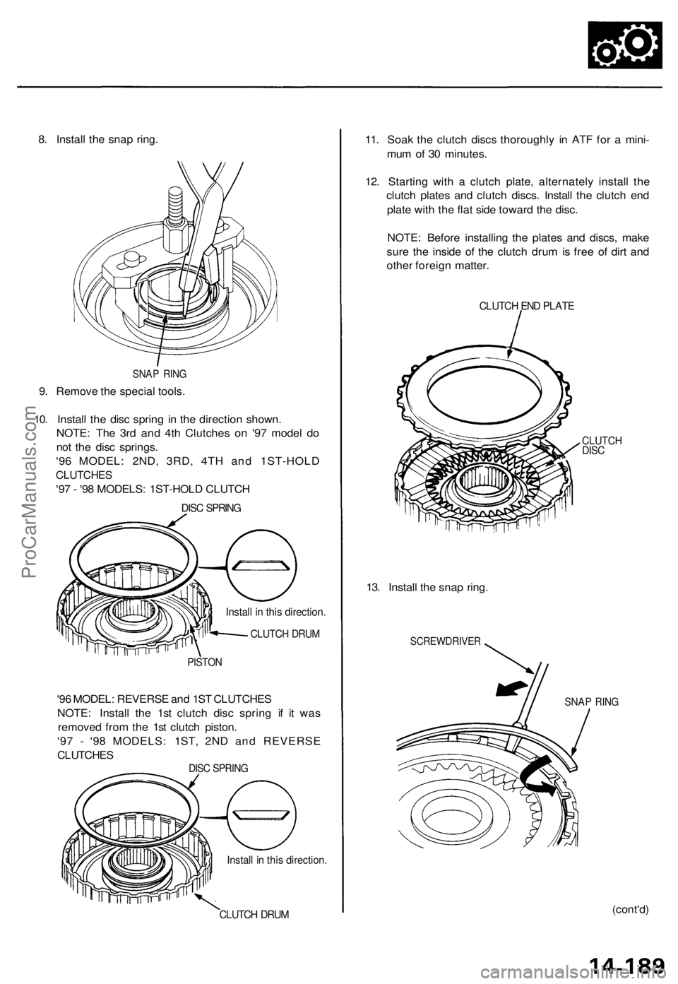
8. Install the snap ring.
SNAP RING
9. Remove the special tools.
10. Install the disc spring in the direction shown.
NOTE: The 3rd and 4th Clutches on '97 model do
not the disc springs.
'96 MODEL: 2ND, 3RD, 4TH and 1ST-HOLD
CLUTCHES
'97 - '98 MODELS: 1ST-HOLD CLUTCH
DISC SPRING
Install in this direction.
CLUTCH DRUM
PISTON
'96 MODEL: REVERSE and 1ST CLUTCHES
NOTE: Install the 1st clutch disc spring if it was
removed from the 1st clutch piston.
'97 - '98 MODELS: 1ST, 2ND and REVERSE
CLUTCHES
DISC SPRING
Install in this direction.
CLUTCH DRUM
11. Soak the clutch discs thoroughly in ATF for a mini-
mum of 30 minutes.
12. Starting with a clutch plate, alternately install the
clutch plates and clutch discs. Install the clutch end
plate with the flat side toward the disc.
NOTE: Before installing the plates and discs, make
sure the inside of the clutch drum is free of dirt and
other foreign matter.
CLUTCH END PLATE
CLUTCH
DISC
13. Install the snap ring.
SCREWDRIVER
SNAP RING
(cont'd)ProCarManuals.com