battery Alfa Romeo 8C 2009 Owner handbook (in English)
[x] Cancel search | Manufacturer: ALFA ROMEO, Model Year: 2009, Model line: 8C, Model: Alfa Romeo 8C 2009Pages: 223, PDF Size: 14.35 MB
Page 93 of 223
91
4
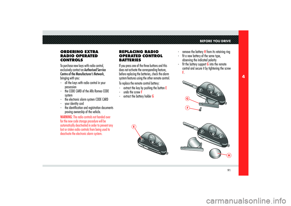
E
GF
H
BEFORE YOU DRIVE
ORDERING EXTRA
RADIO OPERATED
CONTROLS
To purchase new keys with radio control,
exclusively contact an Authorised Service
Centre of the Manufacturer’s Network,
bringing with you:
- all the keys with radio control in your
possession
- the CODE CARD of the Alfa Romeo CODE
system
- the electronic alarm system CODE CARD
- your identity card
- the identifi cation and registration documents
proving ownership of the vehicle. WARNING: The radio controls not handed over
for the new code storage procedure will be
automatically deactivated in order to prevent any
lost or stolen radio controls from being used to
deactivate the electronic alarm system.
REPLACING RADIO
OPERATED CONTROL
BATTERIES
If you press one of the three buttons and this
does not activate the corresponding feature,
before replacing the batteries, check the alarm
system features using the other remote control.
To replace the remote control battery:
- extract the key by pushing the button
E
- undo the screw
F
- extract the battery holder
G
- remove the battery
H from its retaining ring
- fi t a new battery of the same type,
observing the indicated polarity
- fi t the battery support G into the remote
control and secure it by tightening the screw
F.
Page 108 of 223
106
4
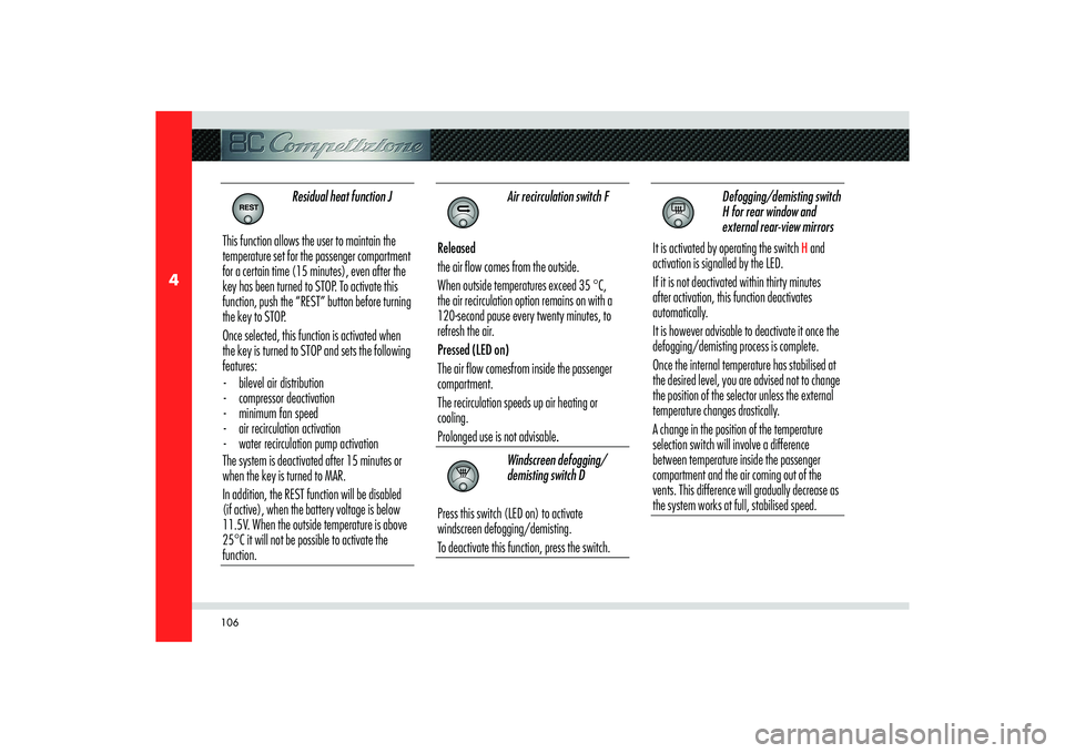
Residual heat function J
This function allows the user to maintain the
temperature set for the passenger compartment
for a certain time (15 minutes), even after the
key has been turned to STOP. To activate this
function, push the “REST” button before turning
the key to STOP.
Once selected, this function is activated when
the key is turned to STOP and sets the following
features:
- bilevel air distribution
- compressor deactivation
- minimum fan speed
- air recirculation activation
- water recirculation pump activation
The system is deactivated after 15 minutes or
when the key is turned to MAR.
In addition, the REST function will be disabled
(if active), when the battery voltage is below
11.5V. When the outside temperature is above
25°C it will not be possible to activate the
function.
Air recirculation switch F
Released
the air flow comes from the outside.
When outside temperatures exceed 35 °C,
the air recirculation option remains on with a
120-second pause every twenty minutes, to
refresh the air.
Pressed (LED on)
The air flow comesfrom inside the passenger
compartment.
The recirculation speeds up air heating or
cooling.
Prolonged use is not advisable.
Windscreen defogging/
demisting switch D
Press this switch (LED on) to activate
windscreen defogging/demisting.
To deactivate this function, press the switch.
Defogging/demisting switch
H for rear window and
external rear-view mirrors
It is activated by operating the switch
H and
activation is signalled by the LED.
If it is not deactivated within thirty minutes
after activation, this function deactivates
automatically.
It is however advisable to deactivate it once the
defogging/demisting process is complete.
Once the internal temperature has stabilised at
the desired level, you are advised not to change
the position of the selector unless the external
temperature changes drastically.
A change in the position of the temperature
selection switch will involve a difference
between temperature inside the passenger
compartment and the air coming out of the
vents. This difference will gradually decrease as
the system works at full, stabilised speed.
Page 117 of 223

115
5
USING THE VEHICLE
STARTING-OFF WHEN
THE ENGINE IS COLD
Start-off slowly, avoiding sudden accelerations
and run the engine at low-medium speeds. High-
performance driving should be avoided until the
water temperature reaches
65–70 °C.EMERGENCY STARTING
WITH AUXILIARY
BATTERY
If the battery is flat, the engine can be started
using another battery having the same or slightly
higher capacity than the flat one.
Proceed as follows:
1) Connect the positive terminals (+) of the
two batteries with a cable specifi cally
designed for this purpose.
2) Connect the negative terminals (-) of the
two batteries with a cable specifi cally
designed for this purpose.
WARNING: The battery is housed in a metal box,
therefore, be extremely careful not to let the
battery charger clips come into contact with it.3) Start the engine.
4) When the engine starts, remove the cables
in reverse order.
If the engine does not start after a number
of attempts, do not continue indefinitely but
consult an Authorised Service Centre of the
Manufacturer’s Network.
CAUTION
Do not carry out this procedure
if you have no experience of it:
incorrect manoeuvres may cause high
levels of electrical discharge and may
even lead to the battery explosion.
CAUTION
You are also advised not to
approach the battery with open flames
or lit cigarettes and not to cause
sparks: risk of explosion and fire!
Page 118 of 223
116
5
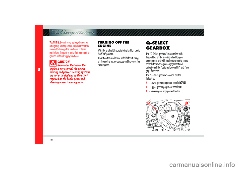
A
B
WARNING: Do not use a battery-charger for
emergency starting under any circumstances:
you could damage the electronic systems,
particularly the control units that manage the
ignition and fuel supply functions.
CAUTION
Remember that when the
engine is not started, the power
braking and power steering systems
are not activated and so the effort
required on the brake pedal and
steering wheel is much greater.
TURNING OFF THE
ENGINE
With the engine idling, rotate the ignition key to
the STOP position.
A burst on the accelerator pedal before turning
off the engine has no purpose and increases fuel
consumption.
Q-SELECT
GEARBOXThe “Q-Select gearbox” is controlled with
the paddles on the steering wheel for gear
engagement and with the buttons on the centre
console for reverse gear engagement and
activation of the “automatic gearshift” and “low
grip” functions.
The “Q-Select gearbox” controls are the
following:A - Lower gear engagement paddle DOWNB - Upper gear engagement paddle UPC - Reverse gear engagement button
Page 120 of 223
118
5
If the symbol
remains on, there is a system
failure. This condition is also indicated by a beep
when the key is turned to position MAR.
WARNING: Contact an Authorised Service
Centre of the Manufacturer’s Network to have
the malfunction corrected.
OPERATION WITH THE
ENGINE OFF
After completing the “system start-up” stage,
the gear currently engaged will appear on the
display:
- N (Neutral)
- R (Reverse)
- D(1
st).
If the indication flashes (may also occur with N)
it means that the gear is not properly engaged or
is disengaged; therefore, request neutral (N) and
then the desired gear.CAUTION
If a horizontal dash appears on
the display, there is a system failure.
When the engine is off, 1st gear, reverse (R) and
neutral (N) can be engaged. Keeping the brake
pedal pressed during the request, you must
proceed as follows:
- N (Neutral): pull both paddles found behind
the steering wheel.
- R (Reverse): press button
C.
- Engaging 1
st gear: pull the UP paddle
towards the steering wheel.
CAUTION
To engage reverse gear, hold
the button C down until the letter R is
displayed.
WARNING: Immediately release the paddles
UP, DOWN and the button R after the gearshift
request. A prolonged manoeuvre may cause
the failure warning light
and the buzzer
to activate. Do not operate the system with the
engine off, to prevent discharging the battery.
Avoid useless gearshifting with the engine off, to
prevent overheating of the pump.
Page 137 of 223
135
5
USING THE VEHICLE
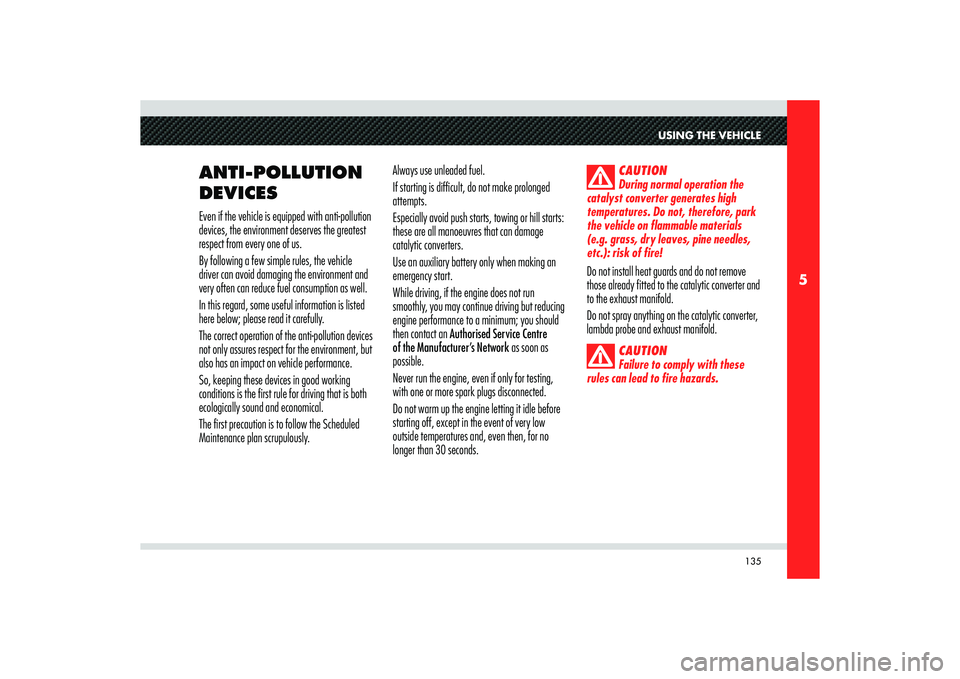
ANTI-POLLUTION
DEVICES Even if the vehicle is equipped with anti-pollution
devices, the environment deserves the greatest
respect from every one of us.
By following a few simple rules, the vehicle
driver can avoid damaging the environment and
very often can reduce fuel consumption as well.
In this regard, some useful information is listed
here below; please read it carefully.
The correct operation of the anti-pollution devices
not only assures respect for the environment, but
also has an impact on vehicle performance.
So, keeping these devices in good working
conditions is the first rule for driving that is both
ecologically sound and economical.
The first precaution is to follow the Scheduled
Maintenance plan scrupulously. Always use unleaded fuel.
If starting is difficult, do not make prolonged
attempts.
Especially avoid push starts, towing or hill starts:
these are all manoeuvres that can damage
catalytic converters.
Use an auxiliary battery only when making an
emergency start.
While driving, if the engine does not run
smoothly, you may continue driving but reducing
engine performance to a minimum; you should
then contact an Authorised Service Centre
of the Manufacturer’s Network as soon as
possible.
Never run the engine, even if only for testing,
with one or more spark plugs disconnected.
Do not warm up the engine letting it idle before
starting off, except in the event of very low
outside temperatures and, even then, for no
longer than 30 seconds.
CAUTION
During normal operation the
catalyst converter generates high
temperatures. Do not, therefore, park
the vehicle on flammable materials
(e.g. grass, dry leaves, pine needles,
etc.): risk of fire!
Do not install heat guards and do not remove
those already fitted to the catalytic converter and
to the exhaust manifold.
Do not spray anything on the catalytic converter,
lambda probe and exhaust manifold.
CAUTION
Failure to comply with these
rules can lead to fire hazards.
Page 141 of 223

139
5
A
USING THE VEHICLE
Malfunction indication
In the event of electric parking brake system
failures, the warning light
! on the display
will come on.
Depending on the message displayed, it signals
the following failures of the EPB system:
- Parking brake failure
If the message warning you to go to the
nearest Authorised Service Centre of the
Manufacturer’s Network is displayed,
drive slowly and remember that the electric
parking brake device is not functioning.
- Excessive temperature. If after leaving the engine off (key turned
to STOP) for about 15 minutes without
using the parking brake, the warning
light illuminates again when the engine
is started, slowly drive to an Authorised
Service Centre of the Manufacturer’s
Network. If the brake failure is accompanied by the
message “Mechanical release only”, the
manual emergency deactivation procedure
must be performed to release the parking
brake.
Deactivating the PARK OFF automatic
operation
To deactivate manual operation of the electric
parking brake, with the engine on, press the
button
A on the dashboard. The words PARK OFF
will appear on the display for 5 seconds and then
the page that was active previously will reappear.
To reactivate automatic operation, press the
button A again, the words PARK ON appear on
the display for 5 seconds.
WARNING: In certain conditions, when the
battery voltage is low, the electric parking brake
activation/deactivation system may temporarily
be deactivated for safety reasons. Therefore,
typically during engine starting when the battery
voltage drops, the message PARK OFF may
temporarily appear on the display indicating that
automatic operation is temporarily disabled.
WARNING: In the case of performance
starting, check that the electric parking brake is
disengaged.
Page 147 of 223
6
Emergency starting ............................................................................................................146
If a tyre gets a puncture ..................................................................................................... 147
If an exterior light goes out .................................................................................................149
If an interior light goes out .................................................................................................. 153
If the battery is fl at ........................................................................................................... 168
If you have to jack up the vehicle ........................................................................................ 169
If you have to tow the vehicle ............................................................................................ 170
In the event of an accident ................................................................................................. 171
IN AN EMERGENCY
Page 159 of 223
157
6
IN AN EMERGENCY
POSITION OF FUSES/
RELAYS
The fuses/relays are located in various parts of
the vehicle, namely:
- On the right hand side of the luggage
compartment.
- Behind the glove compartment, to the left
of the steering wheel.
- In the luggage compartment, next to the
battery.
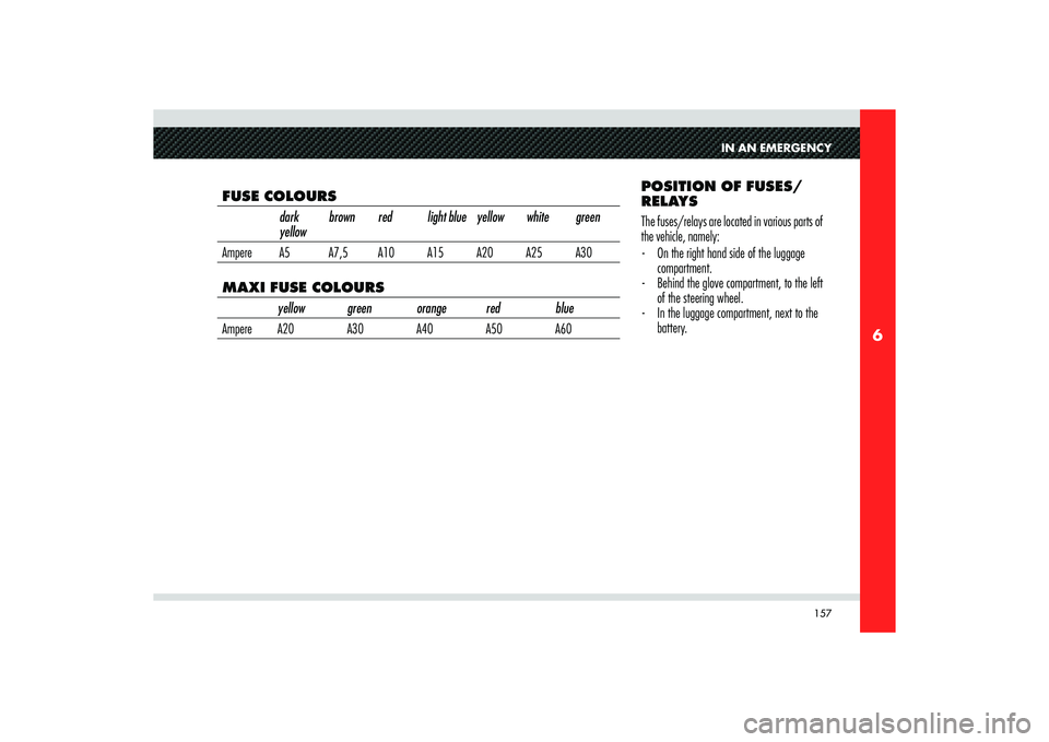
FUSE COLOURS
dark
yellowbrown red light blue yellow white green
Ampere A5 A7,5 A10 A15 A20 A25 A30MAXI FUSE COLOURS
yellow green orange red blue
Ampere A20 A30 A40 A50 A60
Page 161 of 223
159
6
IN AN EMERGENCY
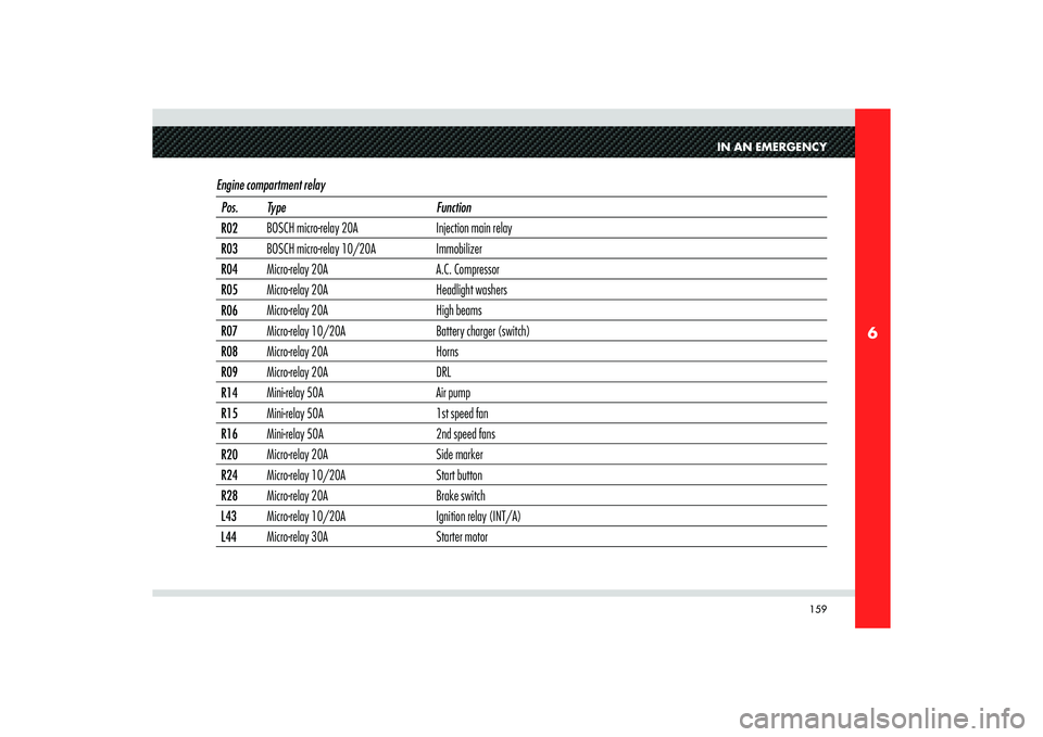
Engine compartment relay Pos. Type Function
R02BOSCH micro-relay 20A Injection main relay
R03BOSCH micro-relay 10/20A Immobilizer
R04Micro-relay 20A A.C. Compressor
R05Micro-relay 20A Headlight washers
R06Micro-relay 20A High beams
R07Micro-relay 10/20A Battery charger (switch)
R08Micro-relay 20A Horns
R09Micro-relay 20A DRL
R14Mini-relay 50A Air pump
R15Mini-relay 50A 1st speed fan
R16Mini-relay 50A 2nd speed fans
R20Micro-relay 20A Side marker
R24Micro-relay 10/20A Start button
R28Micro-relay 20A Brake switch
L43Micro-relay 10/20A Ignition relay (INT/A)
L44Micro-relay 30A Starter motor