ESP Alfa Romeo Brera/Spider 2006 Owner handbook (in English)
[x] Cancel search | Manufacturer: ALFA ROMEO, Model Year: 2006, Model line: Brera/Spider, Model: Alfa Romeo Brera/Spider 2006Pages: 267, PDF Size: 7.21 MB
Page 197 of 267
195
SAFETY
DEVICES
WARNING
LIGHTS AND
MESSAGES
IN AN
EMERGENCY CAR
MAINTENANCE
TECHNICAL
SPECIFICATIONS
INDEX
DASHBOARD
AND
CONTROLS
CORRECT USE
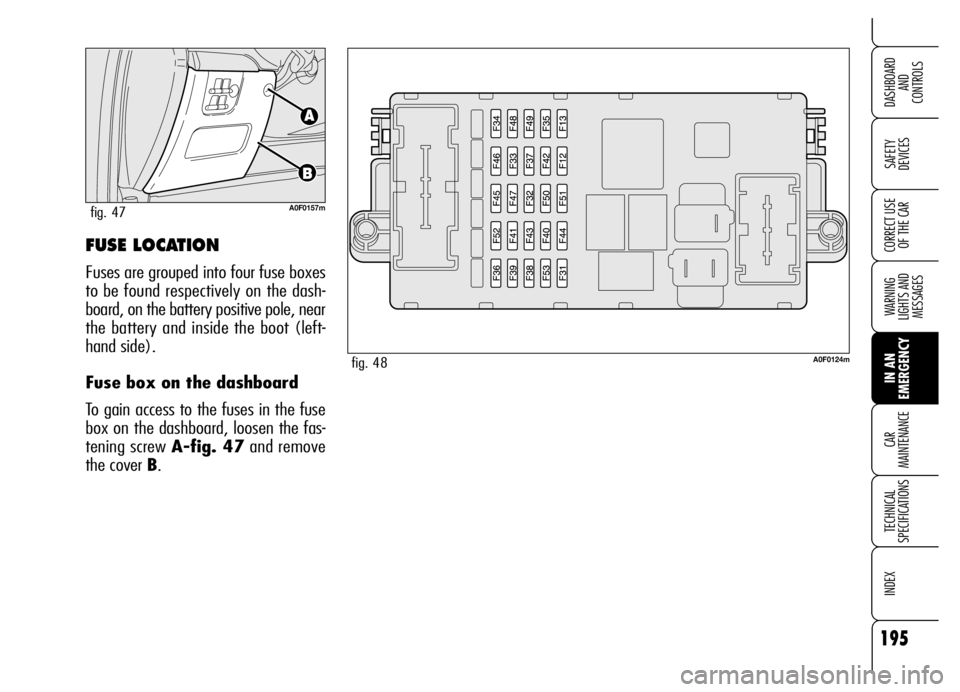
OF THE CARFUSE LOCATION
Fuses are grouped into four fuse boxes
to be found respectively on the dash-
board, on the battery positive pole, near
the battery and inside the boot (left-
hand side).
Fuse box on the dashboard
To gain access to the fuses in the fuse
box on the dashboard, loosen the fas-
tening screw A-fig. 47and remove
the cover B.
A0F0157mfig. 47
A0F0124mfig. 48
Page 218 of 267
216
SAFETY
DEVICES
WARNING
LIGHTS AND
MESSAGES
IN AN
EMERGENCY
CAR
MAINTENANCE
TECHNICAL
SPECIFICATIONS
INDEX
DASHBOARD
AND
CONTROLS
CORRECT USE
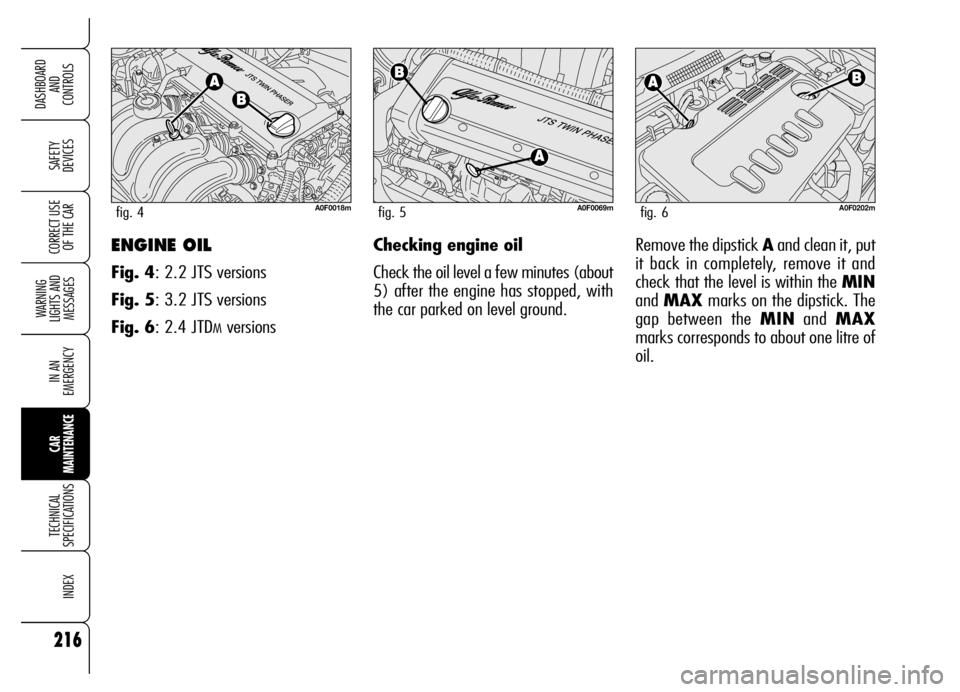
OF THE CARENGINE OIL
Fig. 4: 2.2 JTS versions
Fig. 5: 3.2 JTS versions
Fig. 6: 2.4 JTD
MversionsChecking engine oil
Check the oil level a few minutes (about
5) after the engine has stopped, with
the car parked on level ground.
A0F0018mfig. 4A0F0069mfig. 5A0F0202mfig. 6
Remove the dipstick Aand clean it, put
it back in completely, remove it and
check that the level is within the MIN
and MAXmarks on the dipstick. The
gap between the MINand MAX
marks corresponds to about one litre of
oil.
Page 225 of 267
223
SAFETY
DEVICES
WARNING
LIGHTS AND
MESSAGES
IN AN
EMERGENCY
CAR
MAINTENANCE
TECHNICAL
SPECIFICATIONS
INDEX
DASHBOARD
AND
CONTROLS
CORRECT USE
OF THE CAR
Bright white colourTop up electrolyte Contact Alfa Romeo
Authorized Services
Dark colour withoutLow charge level Charge the battery
green area in the centre(advisable to contact Alfa
Romeo Authorized Services)
Dark colour withElectrolyte level and charge No action
green area in the centresufficient
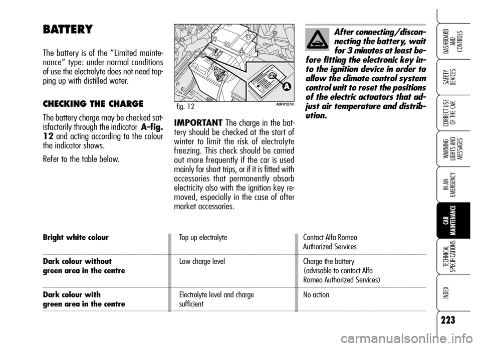
BATTERY
The battery is of the “Limited mainte-
nance” type: under normal conditions
of use the electrolyte does not need top-
ping up with distilled water.
CHECKING THE CHARGE
The battery charge may be checked sat-
isfactorily through the indicator A-fig.
12and acting according to the colour
the indicator shows.
Refer to the table below.
A0F0127mfig. 12
After connecting/discon-
necting the battery, wait
for 3 minutes at least be-
fore fitting the electronic key in-
to the ignition device in order to
allow the climate control system
control unit to reset the positions
of the electric actuators that ad-
just air temperature and distrib-
ution.
IMPORTANT The charge in the bat-
tery should be checked at the start of
winter to limit the risk of electrolyte
freezing. This check should be carried
out more frequently if the car is used
mainly for short trips, or if it is fitted with
accessories that permanently absorb
electricity also with the ignition key re-
moved, especially in the case of after
market accessories.
Page 241 of 267
239
SAFETY
DEVICES
WARNING
LIGHTS AND
MESSAGES
IN AN
EMERGENCY
CAR
MAINTENANCE
TECHNICAL
SPECIFICATIONS
INDEX
DASHBOARD
AND
CONTROLS
CORRECT USE
OF THE CAR
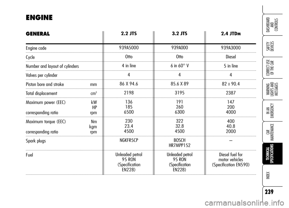
2.2 JTS
939A5000
Otto
4 in line
4
86 X 94.6
2198
136
185
6500
230
23.4
4500
NGKFR5CP
Unleaded petrol
95 RON
(Specification
EN228)3.2 JTS
939A000
Otto
6 in 60° V
4
85.6 X 89
3195
191
260
6300
322
32.8
4500
BOSCH
HR7MPP152
Unleaded petrol
95 RON
(Specification
EN228)2.4 JTDM
939A3000
Diesel
5 in line
4
82
X90.4
2387
147
200
4000
400
40.8
2000
–
Diesel fuel for
motor vehicles
(Specification EN590)
ENGINE
GENERAL
Engine code
Cycle
Number and layout of cylinders
Valves per cylinder
Piston bore and stroke mm
Total displacement cm3
Maximum power (EEC) kW
HP
corresponding ratio rpm
Maximum torque (EEC) Nm
kgm
corresponding ratio rpm
Spark plugs
Fuel
Page 245 of 267
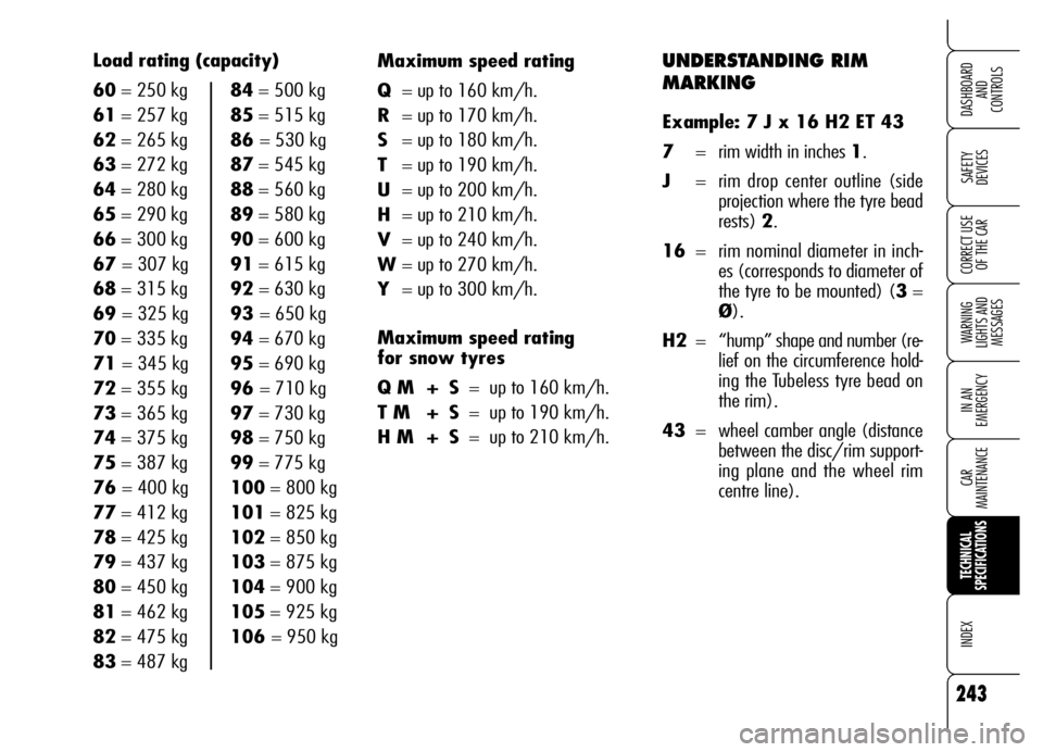
UNDERSTANDING RIM
MARKING
Example: 7 J x 16 H2 ET 43
7= rim width in inches 1.
J= rim drop center outline (side
projection where the tyre bead
rests) 2.
16= rim nominal diameter in inch-
es (corresponds to diameter of
the tyre to be mounted) (3=
Ø).
H2= “hump” shape and number (re-
lief on the circumference hold-
ing the Tubeless tyre bead on
the rim).
43= wheel camber angle (distance
between the disc/rim support-
ing plane and the wheel rim
centre line). Maximum speed rating
Q= up to 160 km/h.
R= up to 170 km/h.
S= up to 180 km/h.
T= up to 190 km/h.
U= up to 200 km/h.
H= up to 210 km/h.
V= up to 240 km/h.
W= up to 270 km/h.
Y= up to 300 km/h.
Maximum speed rating
for snow tyres
Q M + S= up to 160 km/h.
T M + S= up to 190 km/h.
H M + S= up to 210 km/h.
243
SAFETY
DEVICES
WARNING
LIGHTS AND
MESSAGES
IN AN
EMERGENCY
CAR
MAINTENANCE
TECHNICAL
SPECIFICATIONS
INDEX
DASHBOARD
AND
CONTROLS
CORRECT USE
OF THE CAR
Load rating (capacity)
60= 250 kg 84= 500 kg
61= 257 kg 85= 515 kg
62= 265 kg 86 = 530 kg
63= 272 kg 87= 545 kg
64= 280 kg 88= 560 kg
65= 290 kg 89= 580 kg
66= 300 kg 90= 600 kg
67 = 307 kg 91= 615 kg
68= 315 kg 92= 630 kg
69 = 325 kg 93 = 650 kg
70= 335 kg94= 670 kg
71 = 345 kg 95= 690 kg
72= 355 kg 96 = 710 kg
73= 365 kg 97= 730 kg
74= 375 kg98= 750 kg
75= 387 kg 99= 775 kg
76 = 400 kg 100= 800 kg
77= 412 kg 101= 825 kg
78= 425 kg 102= 850 kg
79= 437 kg 103= 875 kg
80= 450 kg 104= 900 kg
81= 462 kg 105= 925 kg
82= 475 kg 106 = 950 kg
83= 487 kg
Page 251 of 267
249
SAFETY
DEVICES
WARNING
LIGHTS AND
MESSAGES
IN AN
EMERGENCY
CAR
MAINTENANCE
TECHNICAL
SPECIFICATIONS
INDEX
DASHBOARD
AND
CONTROLS
CORRECT USE
OF THE CAR
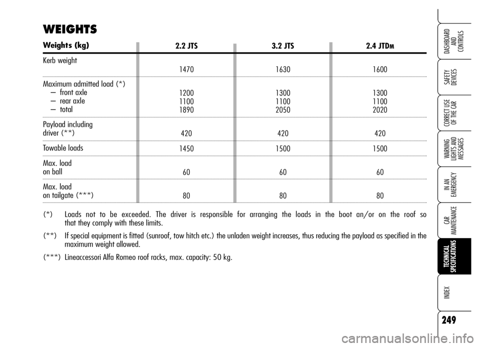
2.2 JTS
1470
1200
1100
1890
420
1450
60
80
3.2 JTS
1630
1300
1100
2050
420
1500
60
80
2.4 JTDM
1600
1300
1100
2020
420
1500
60
80
WEIGHTS
Weights (kg)
Kerb weight
Maximum admitted load (*)
– front axle
– rear axle
– total
Payload including
driver (**)
Towable loads
Max. load
on ball
Max. load
on tailgate (***)
(*) Loads not to be exceeded. The driver is responsible for arranging the loads in the boot an/or on the roof so
that they comply with these limits.
(**) If special equipment is fitted (sunroof, tow hitch etc.) the unladen weight increases, thus reducing the payload as specified in the
maximum weight allowed.
(***) Lineaccessori Alfa Romeo roof racks, max. capacity: 50 kg.