load capacity ALFA ROMEO GIULIA 2021 Owners Manual
[x] Cancel search | Manufacturer: ALFA ROMEO, Model Year: 2021, Model line: GIULIA, Model: ALFA ROMEO GIULIA 2021Pages: 284, PDF Size: 8.87 MB
Page 139 of 284
137
Gross Vehicle Weight Rating (GVWR)
The GVWR is the total permissible weight of
your vehicle including driver, passengers,
vehicle, options and cargo. The label also
specifies maximum capacities of front and
rear axle systems (GAWR). Total load must be
limited so GVWR and front and rear GAWR are
not exceeded.
Payload
The payload of a vehicle is defined as the
allowable load weight a truck can carry,
including the weight of the driver, all passen-
gers, options and cargo.
Gross Axle Weight Rating (GAWR)
The GAWR is the maximum permissible load
on the front and rear axles. The load must be
distributed in the cargo area so that the GAWR
of each axle is not exceeded.
Each axle GAWR is determined by the compo -
nents in the system with the lowest load
carrying capacity (axle, springs, tires or
wheels). Heavier axles or suspension compo -
nents sometimes specified by purchasers for
increased durability do not necessarily
increase the vehicle's GVWR.
Tire Size
The tire size on the Vehicle Certification Label
represents the actual tire size on your vehicle.
Replacement tires must be equal to the load
capacity of this tire size.
Rim Size
This is the rim size that is appropriate for the
tire size listed.
Inflation Pressure
This is the cold tire inflation pressure for your
vehicle for all loading conditions up to full
GAWR.
Curb Weight
The curb weight of a vehicle is defined as the
total weight of the vehicle with all fluids,
including vehicle fuel, at full capacity condi -
tions, and with no occupants or cargo loaded
into the vehicle. The front and rear curb weight
values are determined by weighing your
vehicle on a commercial scale before any
occupants or cargo are added.
Loading
The actual total weight and the weight of the
front and rear of your vehicle at the ground can
best be determined by weighing it when it is
loaded and ready for operation. The entire vehicle should first be weighed on a
commercial scale to ensure that the GVWR
has not been exceeded. The weight on the
front and rear of the vehicle should then be
determined separately to be sure that the load
is properly distributed over the front and rear
axle. Weighing the vehicle may show that the
GAWR of either the front or rear axles has
been exceeded but the total load is within the
specified GVWR. If so, weight must be shifted
from front to rear or rear to front as appro
-
priate until the specified weight limitations are
met. Store the heavier items down low and be
sure that the weight is distributed equally.
Stow all loose items securely before driving.
Improper weight distributions can have an
adverse effect on the way your vehicle steers
and handles and the way the brakes operate.
CAUTION!
Do not load your vehicle any heavier than
the GVWR or the maximum front and rear
GAWR. If you do, parts on your vehicle can
break, or it can change the way your vehicle
handles. This could cause you to lose
control. Also overloading can shorten the
life of your vehicle.
21_GA_OM_EN_USC_t.book Page 137
Page 142 of 284

STARTING AND OPERATING
140
Brakes
The car braking system may be available with
four carbon-ceramic material brake discs, one
on each wheel.
In order to guarantee the maximum braking
capacity for the first use, Alfa Romeo performs
a “run-in” procedure for discs and pads
directly at the factory.
The use of carbon-ceramic material brake
discs guarantees braking features (better
deceleration/pedal load ratio, braking
distances, fading resistance) proportional to
the dynamic features of the car in addition to
considerably decreasing the unsprung compo-
nent weight.
The materials used and the structural features
of the system could generate unusual noises
which have absolutely no adverse effect on
correct operation and reliability of the braking
system.
Greater pressure may need to be applied to
the brake pedal the first time to keep the same
braking capacities in presence of condensa -
tion or salt on the braking surfaces, for
example after washing or if the car is not used
for a long time.
NOTE:
Given the high technological level of this
system, any servicing on it must be performed
by an authorized dealer which exclusively has
the skills needed for the repair and mainte -
nance operations. In case of intensive, high-performance use of
the car, have the efficiency of the
carbon-ceramic material braking system
inspected as shown on the Maintenance Plan
at an authorized dealer.
Driving On Race Tracks
Before driving on a track using a racing style, it
is necessary to:
Attend a race track driving course.
Check all liquid levels in the engine
compartment.
Have the car inspected at an authorized
dealer.
Remember that the car was not designed to be
driven exclusively on the race track and that
this use increases stress and component
wear.
NOTE:
Quadrifoglio front brakes are equipped with
NAO type pads (Non-Asbestos Organic). These
pads are NOT suitable for high thermal loads
(for example track use). If you want to use
vehicle on a track it is recommended to use
the optional CCM Brakes (Carbon Ceramic
Brake disc). Preheating The Carbon Ceramic Material
Brake Discs (If Equipped)
The brake discs must be warmed up to make
them fully efficient. You are advised to perform
the following procedure to achieve optimal
efficiency:
Brake nine times from 80 mph to 18 mph
(130 km/h to 30 km/h) with deceleration
equal to 0.7g (the longitudinal acceleration
value is shown on the instrument panel
display by setting RACE mode and selecting
the “Performance” page) with 20 second
intervals between brake applications; keep
the car at a speed comprised between
37 mph and 62 mph (60 km/h and
100 km/h) and do not brake for 4 minutes to allow the brakes to cool down.
Brake three times from 124 mph to 18 mph
(200 km/h to 30 km/h) with deceleration
equal to 1.1g (ABS operation) with 30
second intervals between brake applica -
tions; keep the car at a speed comprised
between 37 mph and 62 mph (60 km/h
and 100 km/h) and do not brake for
5 minutes to allow the brakes to cool down.
21_GA_OM_EN_USC_t.book Page 140
Page 145 of 284
143
Hill Start Assist (HSA)
This is an integral part of the ESC system and
facilitates starting on slopes, activating auto-
matically in the following cases:
Uphill: vehicle stationary on a road with a
gradient higher than 5%, engine running,
brake pressed and transmission in
NEUTRAL (N) or gear other than REVERSE
(R) engaged.
Downhill: vehicle stationary on a road with a
gradient higher than 5%, engine running,
brake pressed and REVERSE gear engaged.
When starting to move forward from a
complete stop, the ESC system control unit
maintains the braking pressure on the wheels
until the engine torque necessary for starting
is reached, or in any case for a maximum of
two seconds, allowing your right foot to be
moved easily from the brake pedal to the
accelerator.
The system will automatically deactivate after
two seconds without starting, gradually
releasing the braking pressure. During this
release stage, it is possible to hear a typical
mechanical brake release noise, indicating
the imminent movement of the vehicle.
Panic Brake Assist (PBA)
The PBA system is designed to improve the
vehicle’s braking capacity during emergency
braking.
The system detects emergency braking by
monitoring the speed and force with which the
brake pedal is pressed, and consequently
applies the optimal brake pressure. This can
reduce the braking distance: the PBA system
therefore complements the ABS.
WARNING!
Electronic Stability Control (ESC) cannot
prevent the natural laws of physics from
acting on the vehicle, nor can it increase
the traction afforded by prevailing road
conditions. ESC cannot prevent accidents,
including those resulting from excessive
speed in turns, driving on very slippery
surfaces, or hydroplaning. ESC also
cannot prevent accidents resulting from
loss of vehicle control due to inappro -
priate driver input for the conditions. Only
a safe, attentive, and skillful driver can
prevent accidents. The capabilities of an
ESC equipped vehicle must never be
exploited in a reckless or dangerous
manner which could jeopardize the user’s
safety or the safety of others.
Vehicle modifications, or failure to prop -
erly maintain your vehicle, may change
the handling characteristics of your
vehicle, and may negatively affect the
performance of the ESC system. Changes
to the steering system, suspension,
braking system, tire type and size or wheel
size may adversely affect ESC perfor-
mance. Improperly inflated and unevenly
worn tires may also degrade ESC perfor -
mance. Any vehicle modification or poor
vehicle maintenance that reduces the
effectiveness of the ESC system can
increase the risk of loss of vehicle control,
vehicle rollover, personal injury and death.
WARNING!
There may be situations where the Hill Start
Assist (HSA) will not activate and slight
rolling may occur, such as on minor hills or
with a loaded vehicle, or while pulling a
trailer. HSA is not a substitute for active
driving involvement. It is always the driver’s
responsibility to be attentive to distance to
other vehicles, people, and objects, and
most importantly brake operation to ensure
safe operation of the vehicle under all road
conditions. Your complete attention is
always required while driving to maintain
safe control of your vehicle. Failure to follow
these warnings can result in a collision or
serious personal injury.
21_GA_OM_EN_USC_t.book Page 143
Page 239 of 284
237
Tire Terminology And Definitions
Tire Loading And Tire Pressure
NOTE:
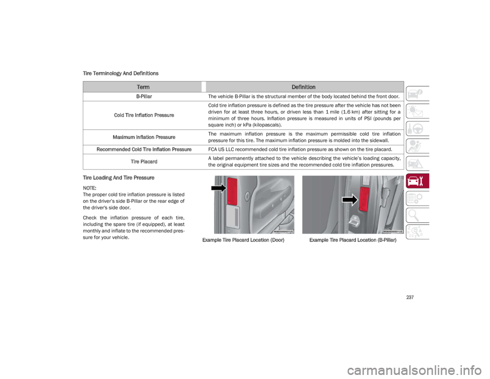
The proper cold tire inflation pressure is listed
on the driver’s side B-Pillar or the rear edge of
the driver's side door.
Check the inflation pressure of each tire,
including the spare tire (if equipped), at least
monthly and inflate to the recommended pres-
sure for your vehicle. Example Tire Placard Location (Door) Example Tire Placard Location (B-Pillar)
TermDefinition
B-PillarThe vehicle B-Pillar is the structural member of the body located behind the front door.
Cold Tire Inflation Pressure Cold tire inflation pressure is defined as the tire pressure after the vehicle has not been
driven for at least three hours, or driven less than 1 mile (1.6 km) after sitting for a
minimum of three hours. Inflation pressure is measured in units of PSI (pounds per
square inch) or kPa (kilopascals).
Maximum Inflation Pressure The maximum inflation pressure is the maximum permissible cold tire inflation
pressure for this tire. The maximum inflation pressure is molded into the sidewall.
Recommended Cold Tire Inflation Pressure FCA US LLC recommended cold tire inflation pressure as shown on the tire placard.
Tire Placard A label permanently attached to the vehicle describing the vehicle’s loading capacity,
the original equipment tire sizes and the recommended cold tire inflation pressures.
21_GA_OM_EN_USC_t.book Page 237
Page 240 of 284
SERVICING AND MAINTENANCE
238
Tire And Loading Information PlacardTire And Loading Information Placard
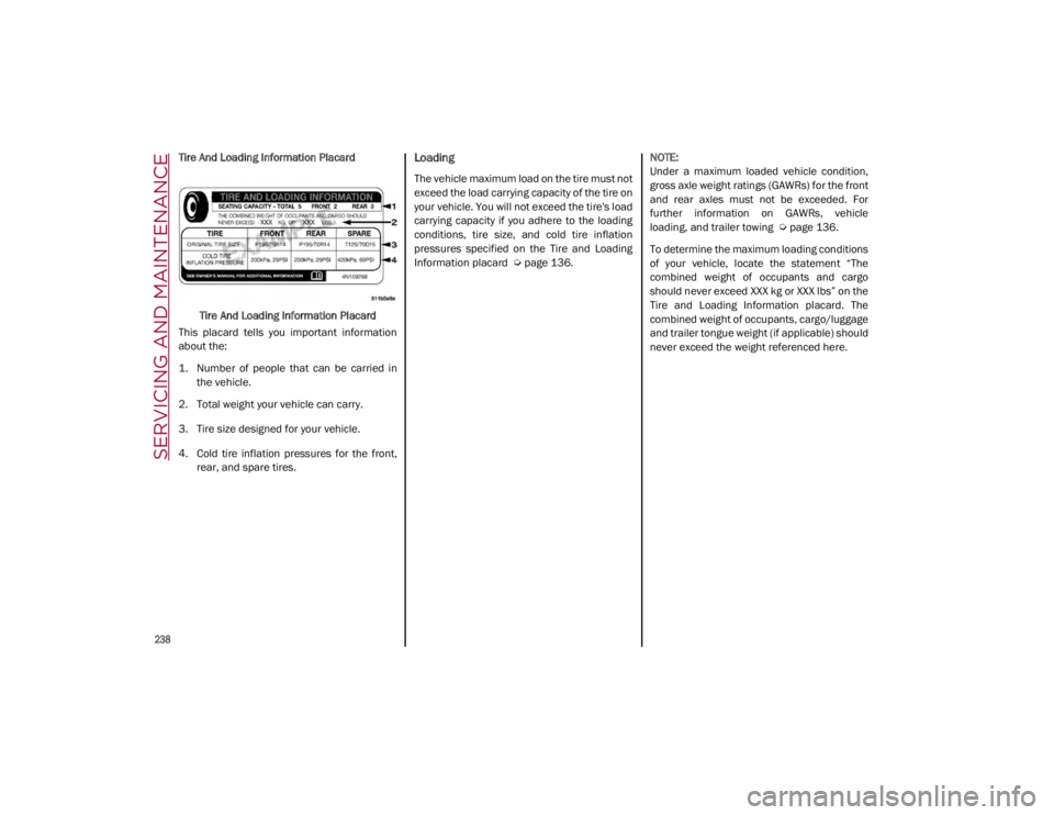
This placard tells you important information
about the:
1. Number of people that can be carried in the vehicle.
2. Total weight your vehicle can carry.
3. Tire size designed for your vehicle.
4. Cold tire inflation pressures for the front, rear, and spare tires.Loading
The vehicle maximum load on the tire must not
exceed the load carrying capacity of the tire on
your vehicle. You will not exceed the tire's load
carrying capacity if you adhere to the loading
conditions, tire size, and cold tire inflation
pressures specified on the Tire and Loading
Information placard
Ú
page 136.
NOTE:
Under a maximum loaded vehicle condition,
gross axle weight ratings (GAWRs) for the front
and rear axles must not be exceeded. For
further information on GAWRs, vehicle
loading, and trailer towing
Ú
page 136.
To determine the maximum loading conditions
of your vehicle, locate the statement “The
combined weight of occupants and cargo
should never exceed XXX kg or XXX lbs” on the
Tire and Loading Information placard. The
combined weight of occupants, cargo/luggage
and trailer tongue weight (if applicable) should
never exceed the weight referenced here.
21_GA_OM_EN_USC_t.book Page 238
Page 241 of 284

239
Steps For Determining Correct Load
Limit—
(1) Locate the statement “The
combined weight of occupants and
cargo should never exceed XXX kg or
XXX lbs.” on your vehicle's placard.
(2) Determine the combined weight of
the driver and passengers that will be
riding in your vehicle.
(3) Subtract the combined weight of the
driver and passengers from XXX kg or
XXX lbs.
(4) The resulting figure equals the avail-
able amount of cargo and luggage load
capacity. For example, if “XXX” amount
equals 1400 lbs. and there will be five
150 lb passengers in your vehicle, the
amount of available cargo and luggage
load capacity is 650 lbs. (1400-750
(5x150) = 650 lbs.) (5) Determine the combined weight of
luggage and cargo being loaded on the
vehicle. That weight may not safely
exceed the available cargo and luggage
load capacity calculated in Step 4.
(6) If your vehicle will be towing a trailer,
load from your trailer will be transferred
to your vehicle. Consult this manual to
determine how this reduces the avail
-
able cargo and luggage load capacity of
your vehicle.Metric Example For Load Limit
For example, if “XXX” amount equals 635 kg
and there will be five 68 kg passengers in your
vehicle, the amount of available cargo and
luggage load capacity is 295 kg (635-340
(5x68) = 295 kg) as shown in step 4.
NOTE:
If your vehicle will be towing a trailer, load
from your trailer will be transferred to your
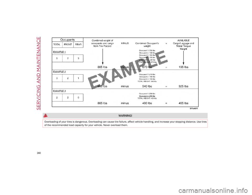
vehicle. The following table shows examples
on how to calculate total load, cargo/
luggage, and towing capacities of your
vehicle with varying seating configurations
and number and size of occupants. This
table is for illustration purposes only and
may not be accurate for the seating and
load carry capacity of your vehicle.
For the following example, the combined
weight of occupants and cargo should never
exceed 865 lbs (392 kg).
21_GA_OM_EN_USC_t.book Page 239
Page 242 of 284
SERVICING AND MAINTENANCE
240
WARNING!
Overloading of your tires is dangerous. Overloading can cause tire failure, affect vehicle handling, and increase your stopping distance. Use tires
of the recommended load capacity for your vehicle. Never overload them.
21_GA_OM_EN_USC_t.book Page 240
Page 244 of 284
SERVICING AND MAINTENANCE
242
Inflation pressures specified on the placard
are always “cold tire inflation pressure”. Cold
tire inflation pressure is defined as the tire
pressure after the vehicle has not been driven
for at least three hours, or driven less than
1 mile (1.6 km) after sitting for a minimum of
three hours. The cold tire inflation pressure
must not exceed the maximum inflation pres-
sure molded into the tire sidewall.
Check tire pressures more often if subject to a
wide range of outdoor temperatures, as tire
pressures vary with temperature changes.
Tire pressures change by approximately 1 psi
(7 kPa) per 12°F (7°C) of air temperature
change. Keep this in mind when checking tire
pressure inside a garage, especially in the
Winter.
Example: If garage temperature = 68°F
(20°C) and the outside temperature = 32°F
(0°C) then the cold tire inflation pressure
should be increased by 3 psi (21 kPa), which
equals 1 psi (7 kPa) for every 12°F (7°C) for
this outside temperature condition.
Tire pressure may increase from 2 to 6 psi (13
to 40 kPa) during operation. DO NOT reduce
this normal pressure build up or your tire pres -
sure will be too low.Tire Pressures For High Speed Operation
FCA US LLC advocates driving at safe speeds
and within posted speed limits. Where speed
limits or conditions are such that the vehicle
can be driven at high speeds, maintaining
correct tire inflation pressure is very
important. Increased tire pressure and
reduced vehicle loading may be required for
high-speed vehicle operation. Refer to an
authorized tire dealer or original equipment
vehicle dealer for recommended safe oper -
ating speeds, loading and cold tire inflation
pressures. Recommended Cold Tire Inflation Pressures
For vehicle speeds below 100 mph (160 km/h),
recommended cold tire inflation pressures are
listed on the Tire And Loading Information
Placard located on driver’s side B-Pillar or the
rear edge of the driver's side door.
When driving at speeds 100 mph (160 km/h)
and above, increased tire pressures and
reduced vehicle loading are required for
high-speed vehicle operation.
For driving speeds above 100 mph (160 km/h)
recommended cold tire inflation pressures are
listed below under "High Speed Tire Inflation
Pressure". Vehicle loading condition must not
exceed 688 lbs. (312 kg) (driver + three
passengers + 88 lbs. (40kg) luggage).
WARNING!
High speed driving with your vehicle under
maximum load is dangerous. The added
strain on your tires could cause them to fail.
You could have a serious collision. Do not
drive a vehicle loaded to the maximum
capacity at continuous speeds above
75 mph (120 km/h).
WARNING!
High speed driving with your vehicle under
maximum load is dangerous. The added
strain on your tires could cause them to fail.
You could have a serious collision.
21_GA_OM_EN_USC_t.book Page 242
Page 246 of 284

SERVICING AND MAINTENANCE
244
Radial Ply Tires
Tire Repair
If your tire becomes damaged, it may be
repaired if it meets the following criteria:
The tire has not been driven on when flat.
The damage is only on the tread section of
your tire (sidewall damage is not repair-
able).
The puncture is no greater than a ¼ of an
inch (6 mm).
Consult an authorized tire dealer for tire
repairs and additional information.
Damaged Run Flat tires, or Run Flat tires that
have experienced a loss of pressure should be
replaced immediately with another Run Flat
tire of identical size and service description
(Load Index and Speed Symbol). Replace the
tire pressure sensor as well as it is not
designed to be reused.
Run Flat Tires — If Equipped
Run Flat tires allow you the capability to drive
50 miles (80 km) at 50 mph (80 km/h) after a
rapid loss of inflation pressure. This rapid loss
of inflation is referred to as the Run Flat mode.
A Run Flat mode occurs when the tire inflation
pressure is of/or below 14 psi (96 kPa). Once
a Run Flat tire reaches the Run Flat mode it
has limited driving capabilities and needs to
be replaced immediately. A Run Flat tire is not
repairable. When a Run Flat tire is changed
after driving with underinflated tire condition,
please replace the TPM sensor as it is not
designed to be reused when driven under Run
Flat mode 14 psi (96 kPa) condition.
NOTE:
TPM Sensor must be replaced after driving the
vehicle on a flat tire condition.
It is not recommended driving a vehicle loaded
at full capacity or to tow a trailer while a tire is
in the Run Flat mode.
See the tire pressure monitoring section for
more information
Ú
page 156.
Tire Spinning
When stuck in mud, sand, snow, or ice condi -
tions, do not spin your vehicle's wheels above
30 mph (48 km/h) or for longer than 30
seconds continuously without stopping.
Tread Wear Indicators
Tread wear indicators are in the original equip -
ment tires to help you in determining when
your tires should be replaced.
Tire Tread
WARNING!
Combining radial ply tires with other types
of tires on your vehicle will cause your
vehicle to handle poorly. The instability
could cause a collision. Always use radial
ply tires in sets of four. Never combine them
with other types of tires.
WARNING!
Fast spinning tires can be dangerous.
Forces generated by excessive wheel
speeds may cause tire damage or failure. A
tire could explode and injure someone. Do
not spin your vehicle's wheels faster than
30 mph (48 km/h) for more than 30
seconds continuously when you are stuck,
and do not let anyone near a spinning
wheel, no matter what the speed.
1 — Worn Tire
2 — New Tire
21_GA_OM_EN_USC_t.book Page 244
Page 248 of 284
SERVICING AND MAINTENANCE
246
Spare Tires — If Equipped
NOTE:
For vehicles equipped with Tire Service Kit
instead of a spare tire, please refer to “Tire
Service Kit” in “In Case Of Emergency” for
further information.
Spare Tire Matching Original Equipped Tire
And Wheel — If Equipped
Your vehicle may be equipped with a spare tire
and wheel equivalent in look and function to
the original equipment tire and wheel found on
the front or rear axle of your vehicle. This spare
tire may be used in the tire rotation for your
vehicle. If your vehicle has this option, refer to
an authorized tire dealer for the recom-
mended tire rotation pattern.
Full Size Spare — If Equipped
The full size spare is for temporary emergency
use only. This tire may look like the originally
equipped tire on the front or rear axle of your
vehicle, but it is not. This spare tire may have
limited tread life. When the tread is worn to the
tread wear indicators, the temporary use full
size spare tire needs to be replaced. Since it is
not the same as your original equipment tire,
replace (or repair) the original equipment tire
and reinstall on the vehicle at the first oppor -
tunity.
Limited Use Spare — If Equipped
The limited use spare tire is for temporary
emergency use only. This tire is identified by a
label located on the limited use spare wheel.
This label contains the driving limitations for
this spare. This tire may look like the original
equipped tire on the front or rear axle of your
vehicle, but it is not. Installation of this limited
use spare tire affects vehicle handling. Since it
is not the same as your original equipment tire, replace (or repair) the original equipment
tire and reinstall on the vehicle at the first
opportunity.
Wheel And Wheel Trim Care
All wheels and wheel trim, especially
aluminum and chrome plated wheels, should
be cleaned regularly using mild (neutral Ph)
soap and water to maintain their luster and to
prevent corrosion. Wash wheels with the same
soap solution recommended for the body of
the vehicle and remember to always wash
when the surfaces are not hot to the touch.
Your wheels are susceptible to deterioration
caused by salt, sodium chloride, magnesium
chloride, calcium chloride, etc., and other road
chemicals used to melt ice or control dust on
dirt roads. Use a soft cloth or sponge and mild
Never use a tire with a smaller load index
or capacity, other than what was originally
equipped on your vehicle. Using a tire with
a smaller load index could result in tire
overloading and failure. You could lose
control and have a collision.
Failure to equip your vehicle with tires
having adequate speed capability can
result in sudden tire failure and loss of
vehicle control.
CAUTION!
Replacing original tires with tires of a
different size may result in false
speedometer and odometer readings.
CAUTION!
Because of the reduced ground clearance,
do not take your vehicle through an
automatic car wash with a compact or
limited use temporary spare installed.
Damage to the vehicle may result.
WARNING! (Continued)
WARNING!
Limited use spares are for emergency use
only. Installation of this limited use spare
tire affects vehicle handling. With this tire,
do not drive more than the speed listed on
the limited use spare wheel. Keep inflated
to the cold tire inflation pressures listed on
your Tire and Loading Information Placard
located on the driver’s side B-Pillar or the
rear edge of the driver’s side door. Replace
(or repair) the original equipment tire at the
first opportunity and reinstall it on your
vehicle. Failure to do so could result in loss
of vehicle control.
21_GA_OM_EN_USC_t.book Page 246