stop start Alfa Romeo Giulietta 2012 Owner handbook (in English)
[x] Cancel search | Manufacturer: ALFA ROMEO, Model Year: 2012, Model line: Giulietta, Model: Alfa Romeo Giulietta 2012Pages: 297, PDF Size: 9.37 MB
Page 81 of 297
77
GETTING
TO KNOW
YOUR CAR
SAFETY
STARTING
AND DRIVING
IN AN
EMERGENCY
SERVICING AND
MAINTENANCE
TECHNICAL
SPECIFICATIONS
CONTENTS
Move the stalk up (unstable position) to limit operation to the time
for which the stalk is held in this position. When released, the stalk
will return to its default position and the wiper will be automati-
cally stopped.WINDOW CLEANING
The right stalk controls windscreen wiper/washer and heated rear
windscreen wiper/washer operation.
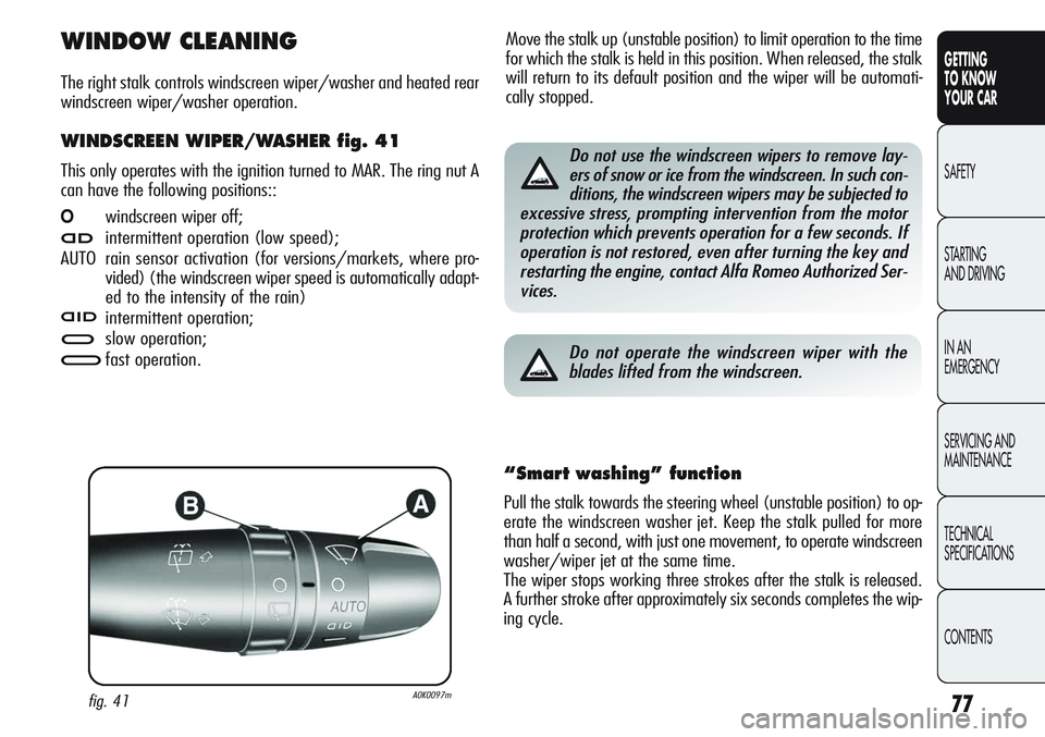
WINDSCREEN WIPER/WASHER fig. 41
This only operates with the ignition turned to MAR. The ring nut A
can have the following positions::
Owindscreen wiper off;
≤intermittent operation (low speed);
AUTO rain sensor activation (for versions/markets, where pro-
vided) (the windscreen wiper speed is automatically adapt-
ed to the intensity of the rain)
nintermittent operation;
≥slow operation;
¥fast operation.
fig. 41A0K0097m
Do not use the windscreen wipers to remove lay-
ers of snow or ice from the windscreen. In such con-
ditions, the windscreen wipers may be subjected to
excessive stress, prompting intervention from the motor
protection which prevents operation for a few seconds. If
operation is not restored, even after turning the key and
restarting the engine, contact Alfa Romeo Authorized Ser-
vices.
Do not operate the windscreen wiper with the
blades lifted from the windscreen.
“Smart washing” function
Pull the stalk towards the steering wheel (unstable position) to op-
erate the windscreen washer jet. Keep the stalk pulled for more
than half a second, with just one movement, to operate windscreen
washer/wiper jet at the same time.
The wiper stops working three strokes after the stalk is released.
A further stroke after approximately six seconds completes the wip-
ing cycle.
Page 84 of 297
80
GETTING
TO KNOW
YOUR CAR
SAFETY
STARTING
AND DRIVING
IN AN
EMERGENCY
SERVICING AND
MAINTENANCE
TECHNICAL
SPECIFICATIONS
CONTENTS
INCREASING THE STORED SPEED
Press the accelerator and store the new speed or move the stalk
upwards (+). Each movement of the stalk will correspond to an
increase in speed of about 1 km/h, while keeping the stalk held
upwards the speed will continuously increase.
REDUCING THE STORED SPEED
Deactivate the device and store the new speed or move the stalk
downwards (–) until the new speed is reached. It will then auto-
matically be stored. Each movement of the stalk will correspond
to a reduction in speed of about 1 km/h, while keeping the stalk
held downwards will continuously reduce the speed.
TURNING THE DEVICE OFF
To release:
❍turn the A ring fig. 43 to OFF;
or
❍stop the engine;
or
❍press the brake pedal, the clutch or the accelerator; in this
last case the system is not actually turned off but the system
gives priority to the acceleration request. The device still re-
mains active, without the need to press the RES button to re-
turn to the previous condition once acceleration is concluded.
STORING THE SPEED
Proceed as follows:
❍turn A ring fig. 43 to ON and press the accelerator until the
car reaches the desired speed;
❍move the stalk upwards (+) for at least one second, then re-
lease it. The speed is now stored and you can therefore release
the accelerator pedal.
If needed (when overtaking for instance), you can accelerate sim-
ply by pressing the accelerator pedal; when you come off the ped-
al, the car will return to the speed memorised previously.
RESTORING STORED SPEED
If the device was disengaged - for example by pressing the brake
or clutch pedal - the stored speed can be reset as follows:
❍accelerate gradually until reaching a speed approaching the one
stored;
❍engage the gear selected at the time of speed storing;
❍press RES button (B-fig. 43).
Page 86 of 297
82
GETTING
TO KNOW
YOUR CAR
SAFETY
STARTING
AND DRIVING
IN AN
EMERGENCY
SERVICING AND
MAINTENANCE
TECHNICAL
SPECIFICATIONS
CONTENTS
B switch operates the map reading light.
B switch positions:
❍central position (position 1): C and D lights are always off;
❍pressed to the left (position 0): C light on;
❍pressed to the right (position 2): D light on.
IMPORTANT Before getting out of the car, make sure that both
switches are in the central position: closing the doors the lights will
go out avoiding to drain the battery.
In any case, if the switch is left inadvertently in the On position,
the ceiling lights will turn off automatically 15 minutes after turn-
ing the engine off.
CEILING LIGHT TIMING
On certain versions, two different timed switching-on modes have
been provided to facilitate getting in/out of the car at night or with
poor lighting.
Timing while getting into the car
The ceiling lights switch on according to the following modes:
❍for about 10 seconds when the front doors are unlocked;
❍for about 3 minutes when one of the doors is opened;
❍for about 10 seconds when the doors are closed.
The timing is interrupted when the ignition is turned to MAR.
Timing while getting out of the car
After removing the key from the ignition switch, the courtesy lights
will turn on as follows:
❍within 2 minutes from turning the engine off for about 10
seconds;
❍for about 3 minutes when one of the doors is opened;
❍when one of the doors is closed for about 10 seconds.
Timing will stop automatically when locking the doors.
Page 90 of 297
86
GETTING
TO KNOW
YOUR CAR
SAFETY
STARTING
AND DRIVING
IN AN
EMERGENCY
SERVICING AND
MAINTENANCE
TECHNICAL
SPECIFICATIONS
CONTENTS
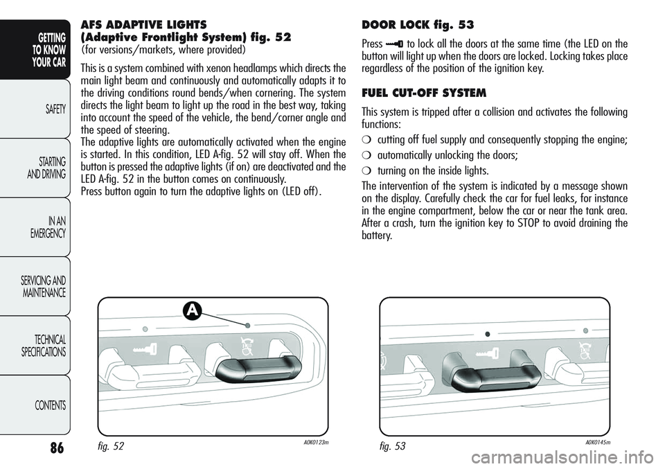
AFS ADAPTIVE LIGHTS
(Adaptive Frontlight System) fig. 52
(for versions/markets, where provided)
This is a system combined with xenon headlamps which directs the
main light beam and continuously and automatically adapts it to
the driving conditions round bends/when cornering. The system
directs the light beam to light up the road in the best way, taking
into account the speed of the vehicle, the bend/corner angle and
the speed of steering.
The adaptive lights are automatically activated when the engine
is started. In this condition, LED A-fig. 52 will stay off. When the
button is pressed the adaptive lights (if on) are deactivated and the
LED A-fig. 52 in the button comes on continuously.
Press button again to turn the adaptive lights on (LED off).
fig. 52A0K0123m
DOOR LOCK fig. 53
Press≈to lock all the doors at the same time (the LED on the
button will light up when the doors are locked. Locking takes place
regardless of the position of the ignition key.
FUEL CUT-OFF SYSTEM
This system is tripped after a collision and activates the following
functions:
❍cutting off fuel supply and consequently stopping the engine;
❍automatically unlocking the doors;
❍turning on the inside lights.
The intervention of the system is indicated by a message shown
on the display. Carefully check the car for fuel leaks, for instance
in the engine compartment, below the car or near the tank area.
After a crash, turn the ignition key to STOP to avoid draining the
battery.
fig. 53A0K0145m
Page 91 of 297
87
GETTING
TO KNOW
YOUR CAR
SAFETY
STARTING
AND DRIVING
IN AN
EMERGENCY
SERVICING AND
MAINTENANCE
TECHNICAL
SPECIFICATIONS
CONTENTS
Follow the procedure below to restore correct operation of the
car:
❍turn the ignition key to MAR;
❍activate the right-hand direction indicator;
❍deactivate the right-hand direction indicator;
❍activate the left-hand direction indicator;
❍deactivate the left-hand direction indicator;
❍activate the right-hand direction indicator;
❍deactivate the right-hand direction indicator;
❍activate the left-hand direction indicator;
❍deactivate the left-hand direction indicator;
❍turn the ignition key to STOP.
If, after a collision, you smell fuel or notice leaks from
the fuel system, do not reset the system to avoid fire
risk.
INTERIOR FITTINGS
GLOVE COMPARTMENT
Upper compartment
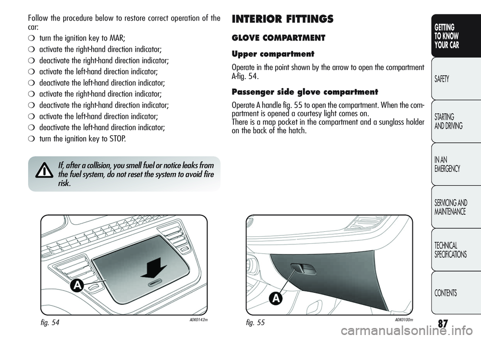
Operate in the point shown by the arrow to open the compartment
A-fig. 54.
Passenger side glove compartment
Operate A handle fig. 55 to open the compartment. When the com-
partment is opened a courtesy light comes on.
There is a map pocket in the compartment and a sunglass holder
on the back of the hatch.
fig. 54A0K0142mfig. 55A0K0100m
Page 96 of 297
92
GETTING
TO KNOW
YOUR CAR
SAFETY
STARTING
AND DRIVING
IN AN
EMERGENCY
SERVICING AND
MAINTENANCE
TECHNICAL
SPECIFICATIONS
CONTENTS
ELECTRIC SUN ROOF
(for versions/markets, where provided)
The sun roof comprises two glass panels; the front one is mobile
and the rear one fixed. These are equipped with two sun blinds
(front and rear) that can be moved manually. With the sun roof
closed, the blinds can be placed in any position.
OPERATION
The sunroof can be operated only with the ignition key turned to
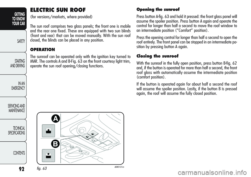
MAR. The controls A and B-Fig. 63 on the front courtesy light trim,
operate the sun roof opening/closing functions.
Opening the sunroof
Press button A-fig. 63 and hold it pressed: the front glass panel will
assume the spoiler position. Press button A again and operate the
control for longer than half a second to move the roof window to
an intermediate position (“Comfort” position).
Press the opening control for longer than half a second to open the
roof entirely. The front panel can be stopped in an intermediate po-
sition by pressing button A again.
Closing the sunroof
With the sunroof in the fully open position, press button B-fig. 62
and, if the button is operated for more than half a second, the front
roof glass with automatically assume the intermediate position
(comfort position).
If the button is operated again for about half a second the roof
will assume the spoiler position. Lastly, if the button B is pressed
again, the roof will assume the fully closed position.
fig. 63A0K0131m
Page 97 of 297
93
GETTING
TO KNOW
YOUR CAR
SAFETY
STARTING
AND DRIVING
IN AN
EMERGENCY
SERVICING AND
MAINTENANCE
TECHNICAL
SPECIFICATIONS
CONTENTSWhen leaving the car, always remove the key from
the ignition device to avoid the risk of injury due
to accidental operation of the sun roof; it presents
a risk to those left on board: improper use of the roof
can be dangerous. Before round during operation, always
check that no-one is at risk of being injured by the mov-
ing sunroof or by objects getting caught and dragged
by it.
Do not open the sun roof in the presence of snow
or ice: it may be damaged.
fig. 64A0K0233m
SUN CURTAINS
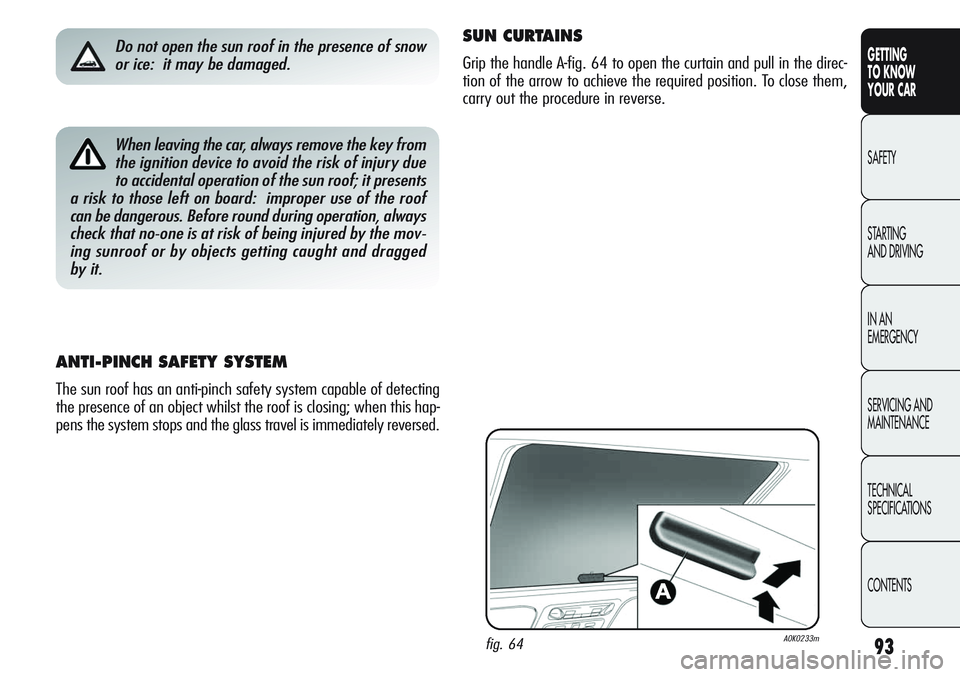
Grip the handle A-fig. 64 to open the curtain and pull in the direc-
tion of the arrow to achieve the required position. To close them,
carry out the procedure in reverse.
ANTI-PINCH SAFETY SYSTEM
The sun roof has an anti-pinch safety system capable of detecting
the presence of an object whilst the roof is closing; when this hap-
pens the system stops and the glass travel is immediately reversed.
Page 102 of 297
98
GETTING
TO KNOW
YOUR CAR
SAFETY
STARTING
AND DRIVING
IN AN
EMERGENCY
SERVICING AND
MAINTENANCE
TECHNICAL
SPECIFICATIONS
CONTENTS
ELECTRIC WINDOWS
The window winders work with the ignition key at MAR and for
approximately three minutes after turning the key to STOP or ex-
tracting it and opening one of the front doors.
The control buttons are located in the door panels (the driver’s door
panel can be used to operate all the windows).
An anti-pinch device is operated when the front and rear windows
are wound up.
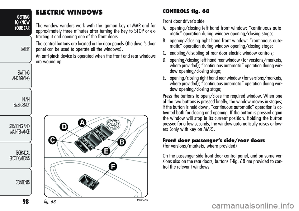
CONTROLS fig. 68
Front door driver’s side
A. opening/closing left hand front window; “continuous auto-
matic” operation during window opening/closing stage;
B. opening/closing right hand front window; “continuous auto-
matic” operation during window opening/closing stage;
C. enabling/disabling of rear door electric window controls;
D. opening/closing left hand rear window (for versions/markets,
where provided); “continuous automatic” operation during win-
dow opening/closing stage;
E. opening/closing right hand rear window (for versions/markets,
where provided); “continuous automatic” operation during win-
dow opening/closing stage;
Press the buttons to open/close the required window. When one
of the two buttons is pressed briefly, the window moves in stages;
if the button is held down, “continuous automatic” operation is ac-
tivated both for closing and opening. If the button is pressed again
the window will stop in its current position. Holding the button
pressed for a few seconds, the window automatically raises or low-
ers (only with key on MAR).
Front door passenger’s side/rear doors
(for versions/markets, where provided)
On the passenger side front door control panel, and on some ver-
sions also on the rear doors, buttons F-fig. 68 are provided to con-
trol the relevant windows
fig. 68A0K0067m
Page 103 of 297
99
GETTING
TO KNOW
YOUR CAR
SAFETY
STARTING
AND DRIVING
IN AN
EMERGENCY
SERVICING AND
MAINTENANCE
TECHNICAL
SPECIFICATIONS
CONTENTS
IMPORTANT With ignition key at STOP or removed, the electric win-
dows remain active for about 3 minutes and are deactivated the
moment a door is opened.
IMPORTANT On some versions when the
Ëbutton on the remote
control is pressed for longer than 2 seconds the windows will open,
whilst if the
Ábutton is pressed for longer than 2 seconds the
windows will close.
The system conforms to the 2000/4/EC standard
concerning the safety of passengers leaning out of
the passenger compartment.
Incorrect use of the electric windows may be danger-
ous. Before and during operation, always check that
no passenger is at risk of being injured directly by
the moving window or by objects getting caught in or dragged
by the window. When leaving the car, always remove the key
from the ignition device to avoid the risk of injury due to ac-
cidental operation of the electric windows. This is a danger to
the people still on board.
Anti-pinch device
The car is equipped with an anti-pinch safety device for the upwards
motion of the windows.
The windows are fitted with an anti-pinch safety system that de-
tects the presence of an obstacle when they are closing and cuts
in by stopping the window and reversing it according to the posi-
tion of the window. This device is also useful when the windows
are activated accidentally by children on board the car.
The anti-pinch function is active both during manual and automat-
ic operation of the electric windows. Following the intervention of
the anti-pinch system, the window travel is immediately interrupt-
ed and subsequently reversed until the lower end of travel is
reached. The window cannot be operated in any way during this
time.
IMPORTANT If the anti-pinch protection intervenes 5 consecutive
times within a minute or is faulty, the automatic closing operation
of the window is inhibited, only allowing it in steps of half a sec-
ond; the button is released for the subsequent manoeuvre.
Open the concerned window to restore correct operation of the sys-
tem.
Page 104 of 297
100
GETTING
TO KNOW
YOUR CAR
SAFETY
STARTING
AND DRIVING
IN AN
EMERGENCY
SERVICING AND
MAINTENANCE
TECHNICAL
SPECIFICATIONS
CONTENTS
Electric window system initialisation
The system must be re-initialised after disconnecting the battery
or if the relevant protection fuse is blown.
Initialisation procedure:
❍fully close the window manually to initialise;
❍after the window has reached the upper end of travel, hold the
up button pressed for at least one second.
IMPORTANT For versions/markets where provided, following the
disconnection of the power supply (replacing or disconnecting the
battery or replacing the protection fuse for the electric window con-
trol units), the automatic setting for the electric windows must be
reset.The reset operation should be carried out with the doors closed
according to the following procedure:
1. completely lower the driver-side window and keep the button
pressed for at least 3 seconds once the end of travel position
has been reached (lower end stop);
2. completely raise the driver-side window and keep the button
pressed for at least 3 seconds once the end of travel position
has been reached (upper end stop);
3. repeat stages 1 and 2 also for the passenger’s window
4. check that the initialisation has taken place correctly by check-
ing the automatic operation of the windows.