seats Alfa Romeo MiTo 2014 Owner's Manual
[x] Cancel search | Manufacturer: ALFA ROMEO, Model Year: 2014, Model line: MiTo, Model: Alfa Romeo MiTo 2014Pages: 280, PDF Size: 8.79 MB
Page 24 of 280
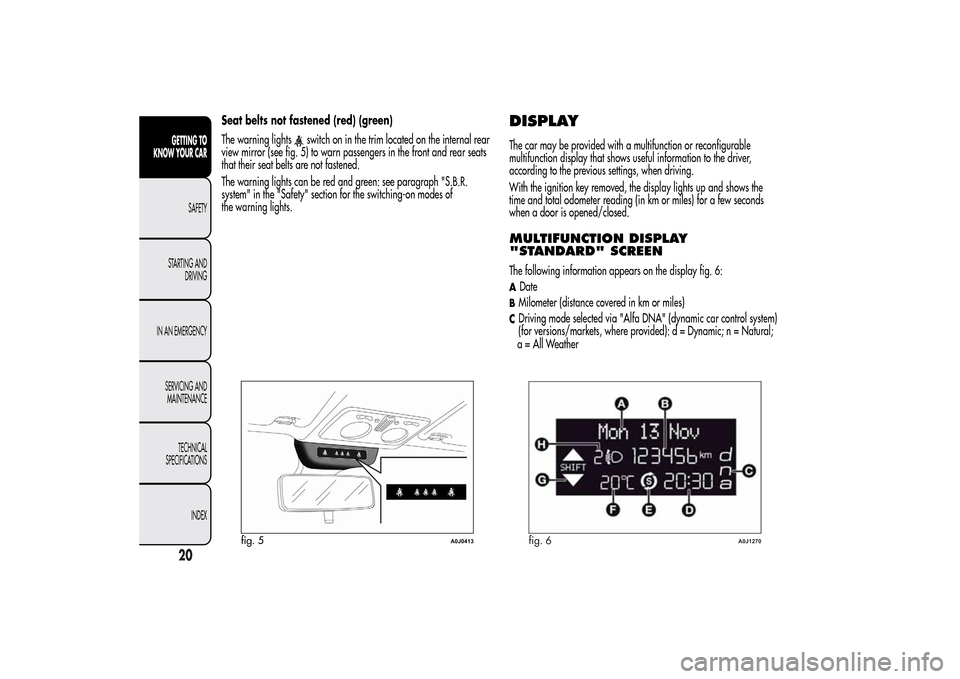
Seat belts not fastened (red) (green)
The warning lights
switch on in the trim located on the internal rear
view mirror (see fig. 5) to warn passengers in the front and rear seats
that their seat belts are not fastened.
The warning lights can be red and green: see paragraph "S.B.R.
system" in the "Safety" section for the switching-on modes of
the warning lights.
DISPLAYThe car may be provided with a multifunction or reconfigurable
multifunction display that shows useful information to the driver,
according to the previous settings, when driving.
With the ignition key removed, the display lights up and shows the
time and total odometer reading (in km or miles) for a few seconds
when a door is opened/closed.MULTIFUNCTION DISPLAY
"STANDARD" SCREENThe following information appears on the display fig. 6:ADateBMilometer (distance covered in km or miles)CDriving mode selected via "Alfa DNA" (dynamic car control system)
(for versions/markets, where provided): d = Dynamic; n = Natural;
fig. 5
A0J0413
fig. 6
A0J1270
20GETTING TO
KNOW YOUR CAR
SAFETY
STARTING AND
DRIVING
IN AN EMERGENCY
SERVICING AND
MAINTENANCE
TECHNICAL
SPECIFICATIONS
INDEX
a = All Weather
Page 48 of 280
SEATSFRONT SEATS
All adjustments must be made with the car stationary.
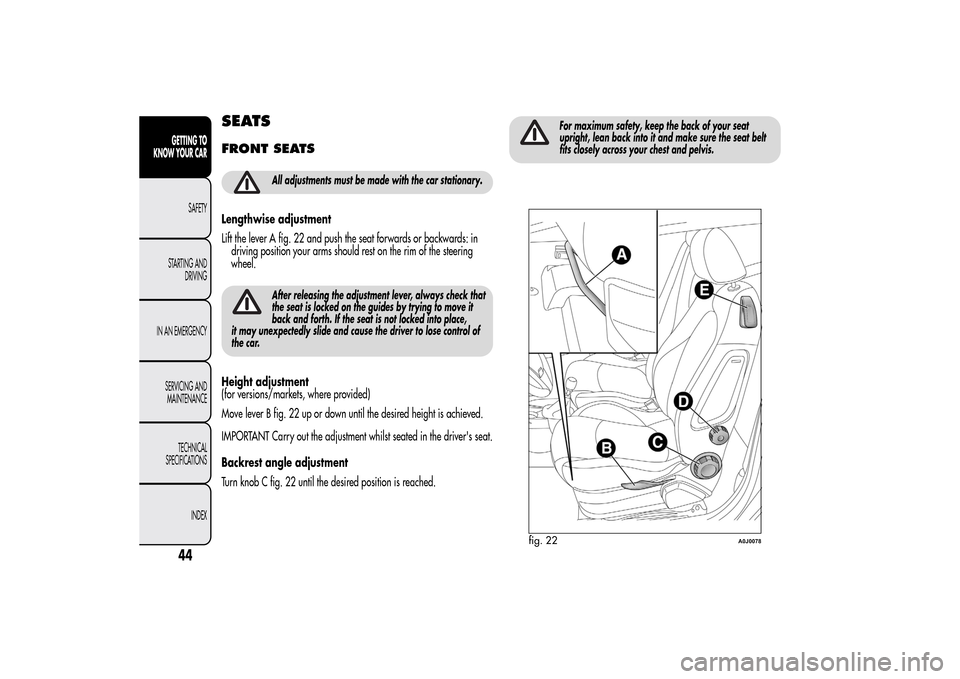
Lengthwise adjustment
Lift the lever A fig. 22 and push the seat forwards or backwards: in
driving position your arms should rest on the rim of the steering
wheel.
After releasing the adjustment lever, always check that
the seat is locked on the guides by trying to move it
back and forth. If the seat is not locked into place,
it may unexpectedly slide and cause the driver to lose control of
the car.
Height adjustment
(for versions/markets, where provided)
Move lever B fig. 22 up or down until the desired height is achieved.
IMPORTANT Carry out the adjustment whilst seated in the driver's seat.
Backrest angle adjustment
Turn knob C fig. 22 until the desired position is reached.
For maximum safety, keep the back of your seat
upright, lean back into it and make sure the seat belt
fits closely across your chest and pelvis.
fig. 22
A0J0078
44GETTING TO
KNOW YOUR CAR
SAFETY
STARTING AND
DRIVING
IN AN EMERGENCY
SERVICING AND
MAINTENANCE
TECHNICAL
SPECIFICATIONS
INDEX
Page 49 of 280
Lumbar adjustment
(for versions/markets, where provided)
Turn knob D fig. 22 until the desired position is reached.
Backrest folding
To access the rear seats, pull handle E upwards fig. 22: the backrest
will fold and the seat will slide forwards when you push the backrest.
Moving the backrest backwards will return the seat to its initial
position.
Always check that the seat is firmly locked on the
guides, trying to push it forwards and backwards.
Seat heating
(for versions/markets, where provided)
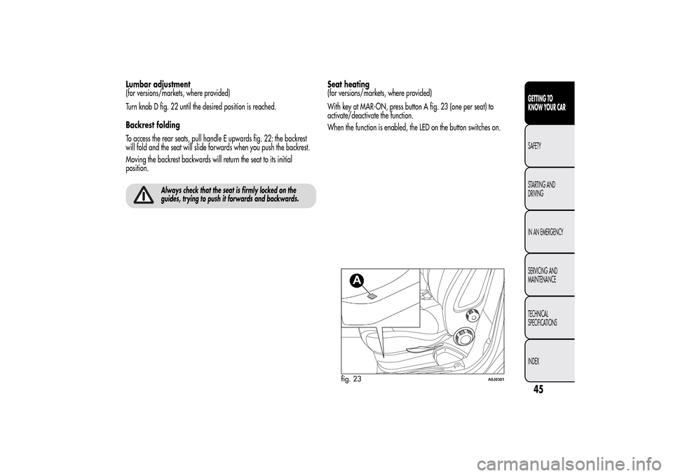
With key at MAR-ON, press button A fig. 23 (one per seat) to
activate/deactivate the function.
When the function is enabled, the LED on the button switches on.
fig. 23
A0J0301
45GETTING TO
KNOW YOUR CARSAFETY
STARTING AND
DRIVING
IN AN EMERGENCY
SERVICING AND
MAINTENANCE
TECHNICAL
SPECIFICATIONS
INDEX
Page 50 of 280
SPORTS CONFIGURATION FRONT
SEATS(for versions/markets, where provided)
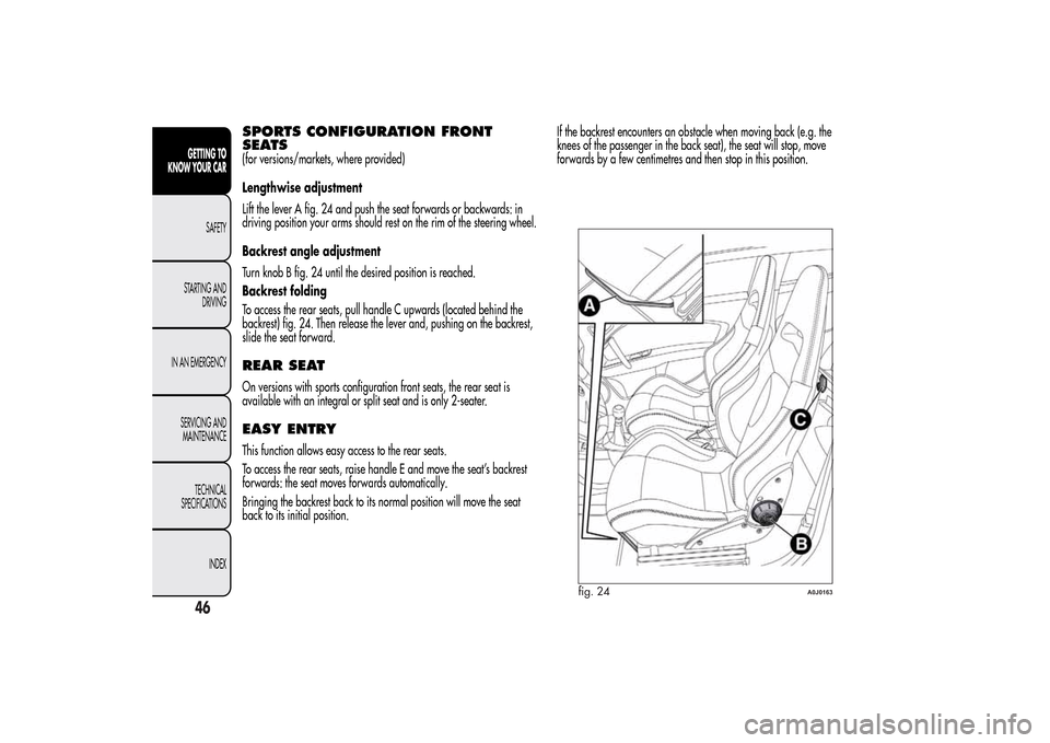
Lengthwise adjustment
Lift the lever A fig. 24 and push the seat forwards or backwards: in
driving position your arms should rest on the rim of the steering wheel.
Backrest angle adjustment
Turn knob B fig. 24 until the desired position is reached.
Backrest folding
To access the rear seats, pull handle C upwards (located behind the
backrest) fig. 24. Then release the lever and, pushing on the backrest,
slide the seat forward.REAR SEATOn versions with sports configuration front seats, the rear seat is
available with an integral or split seat and is only 2-seater.EASY ENTRYThis function allows easy access to the rear seats.
To access the rear seats, raise handle E and move the seat’s backrest
forwards: the seat moves forwards automatically.
Bringing the backrest back to its normal position will move the seat
back to its initial position.If the backrest encounters an obstacle when moving back (e.g. the
knees of the passenger in the back seat), the seat will stop, move
forwards by a few centimetres and then stop in this position.
fig. 24
A0J0163
46GETTING TO
KNOW YOUR CAR
SAFETY
STARTING AND
DRIVING
IN AN EMERGENCY
SERVICING AND
MAINTENANCE
TECHNICAL
SPECIFICATIONS
INDEX
Page 52 of 280
REARTwo height-adjustable head restraints are provided for the back seats
(to adjust the height see the previous paragraph).
On some versions a head restraint is also provided for the central seat.
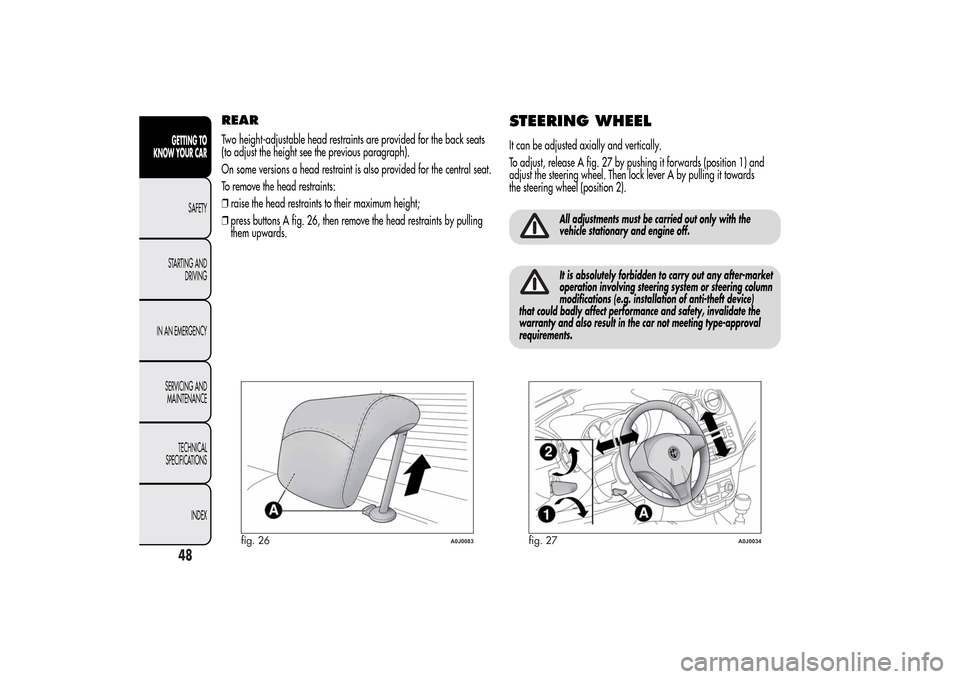
To remove the head restraints:
❒raise the head restraints to their maximum height;
❒press buttons A fig. 26, then remove the head restraints by pulling
them upwards.
STEERING WHEELIt can be adjusted axially and vertically.
To adjust, release A fig. 27 by pushing it forwards (position 1) and
adjust the steering wheel. Then lock lever A by pulling it towards
the steering wheel (position 2).
All adjustments must be carried out only with the
vehicle stationary and engine off.It is absolutely forbidden to carry out any after-market
operation involving steering system or steering column
modifications (e.g. installation of anti-theft device)
that could badly affect performance and safety, invalidate the
warranty and also result in the car not meeting type-approval
requirements.
fig. 26
A0J0083
fig. 27
A0J0034
48GETTING TO
KNOW YOUR CAR
SAFETY
STARTING AND
DRIVING
IN AN EMERGENCY
SERVICING AND
MAINTENANCE
TECHNICAL
SPECIFICATIONS
INDEX
Page 55 of 280
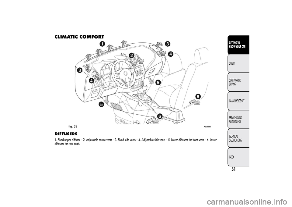
CLIMATIC COMFORTDIFFUSERS1. Fixed upper diffuser – 2. Adjustable centre vents – 3. Fixed side vents – 4. Adjustable side vents – 5. Lower diffusers for front seats – 6. Lower
diffusers for rear seats
fig. 32
A0J0036
51GETTING TO
KNOW YOUR CARSAFETY
STARTING AND
DRIVING
IN AN EMERGENCY
SERVICING AND
MAINTENANCE
TECHNICAL
SPECIFICATIONS
INDEX
Page 78 of 280
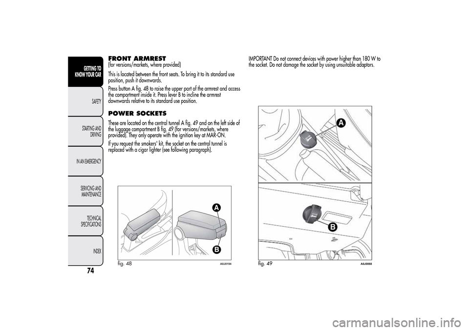
FRONT ARMREST(for versions/markets, where provided)
This is located between the front seats. To bring it to its standard use
position, push it downwards.
Press button A fig. 48 to raise the upper part of the armrest and access
the compartment inside it. Press lever B to incline the armrest
downwards relative to its standard use position.POWER SOCKETSThese are located on the central tunnel A fig. 49 and on the left side of
the luggage compartment B fig. 49 (for versions/markets, where
provided). They only operate with the ignition key at MAR-ON.
If you request the smokers' kit, the socket on the central tunnel is
replaced with a cigar lighter (see following paragraph).IMPORTANT Do not connect devices with power higher than 180 W to
the socket. Do not damage the socket by using unsuitable adaptors.
fig. 48
A0J0194
fig. 49
A0J0068
74GETTING TO
KNOW YOUR CAR
SAFETY
STARTING AND
DRIVING
IN AN EMERGENCY
SERVICING AND
MAINTENANCE
TECHNICAL
SPECIFICATIONS
INDEX
Page 88 of 280
LUGGAGE COMPARTMENTThe luggage compartment is unlocked electrically and cannot be
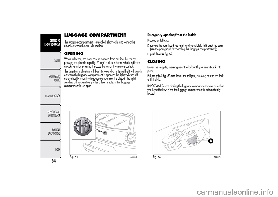
unlocked when the car is in motion.OPENINGWhen unlocked, the boot can be opened from outside the car by
pressing the electric logo fig. 61 until a click is heard which indicates
unlocking or by pressing the
button on the remote control.
The direction indicators will flash twice and an internal light will switch
on when the luggage compartment is opened: the light switches off
automatically when the luggage compartment is closed. The light
switches off automatically after a few minutes if the luggage
compartment is left open.Emergency opening from the inside
Proceed as follows:
❒remove the rear head restraints and completely fold back the seats
(see the paragraph “Expanding the luggage compartment”);
❒push lever A fig. 62.
CLOSINGLower the tailgate, pressing near the lock until you hear it click into
place.
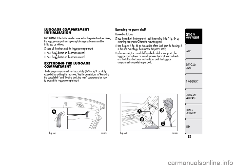
Pull the tab A fig. 63 and lower the tailgate, pressing next to the lock
until it clicks.
IMPORTANT Before closing the luggage compartment make sure that
you have the keys since the luggage compartment is automatically
locked.
fig. 61
A0J0058
fig. 62
A0J0178
84GETTING TO
KNOW YOUR CAR
SAFETY
STARTING AND
DRIVING
IN AN EMERGENCY
SERVICING AND
MAINTENANCE
TECHNICAL
SPECIFICATIONS
INDEX
Page 89 of 280
LUGGAGE COMPARTMENT
INITIALISATIONIMPORTANT If the battery is disconnected or the protection fuse blows,
the luggage compartment opening/closing mechanism must be
initialised as follows:
❒close all the doors and the luggage compartment;
❒Press the
button on the remote control;
❒Press thebutton on the remote control.
EXTENDING THE LUGGAGE
COMPARTMENTThe luggage compartment can be partially (1/3 or 2/3) or totally
extended by splitting the rear seat. See the descriptions in “Removing
the parcel shelf” and “Folding back the seats” paragraphs for how
to expand the luggage compartment.Removing the parcel shelf
Proceed as follows:
❒free the ends of the two parcel shelf B mounting links A fig. 64 by
removing the eyelets C from the mounting pins;
❒free the pins A fig. 65 on the outside of the shelf from the housings B
in the side mountings, then remove the parcel shelf;
❒after removal, the parcel shelf can be loaded sideways into the
luggage compartment or placed between the front seat backrests
and the folded-back rear seat cushions (with the luggage
compartment completely expanded).
fig. 63
A0J0079
fig. 64
A0J0080
85GETTING TO
KNOW YOUR CARSAFETY
STARTING AND
DRIVING
IN AN EMERGENCY
SERVICING AND
MAINTENANCE
TECHNICAL
SPECIFICATIONS
INDEX
Page 90 of 280
Folding the seatsProceed as follows:
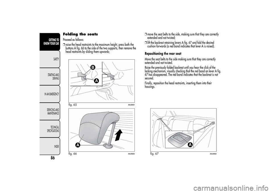
❒raise the head restraints to the maximum height, press both the
buttons A fig. 66 to the side of the two supports, then remove the
head restraints by sliding them upwards;❒move the seat belts to the side, making sure that they are correctly
extended and not twisted;
❒lift the backrest retaining levers A fig. 67 and fold the desired
cushion forwards (a red band indicates that lever A is raised).
Repositioning the rear seat
Move the seat belts to the side making sure that they are correctly
extended and not twisted.
Raise the previously folded backrest until you hear the click of the
locking mechanism, visually checking that the red band on lever A fig.
67 has disappeared. The red band indicates that the backrest is not
secured.
Finally, reposition the head restraints, inserting them into their
housings.
fig. 65
A0J0081
fig. 66
A0J0083
fig. 67
A0J0082
86GETTING TO
KNOW YOUR CAR
SAFETY
STARTING AND
DRIVING
IN AN EMERGENCY
SERVICING AND
MAINTENANCE
TECHNICAL
SPECIFICATIONS
INDEX