mirror ASTON MARTIN V8 VANTAGE 2010 Workshop Manual
[x] Cancel search | Manufacturer: ASTON MARTIN, Model Year: 2010, Model line: V8 VANTAGE, Model: ASTON MARTIN V8 VANTAGE 2010Pages: 947, PDF Size: 43.21 MB
Page 3 of 947

Contents
Issue 5, January 2010 Workshop Manual 0-0-3
V8 Vantage Workshop Manual
Contents
IntroductionWelcome .............................................................. 0-0-6
Safety Precautions ................................................. 0-0-7
Lifting and Jacking ................................................. 0-0-9
Vehicle Recovery ................................................ 0-0-10
Vehicle Identification Number ............................ 0-0-11
Body System (01.00) Body Structure (01.01) .......................................... 1-1-4
Front End System (01.02) ...................................... 1-2-1
Body Closures (01.03) ........................................... 1-3-1
Interior Trim (01.05) ............................................. 1-4-1
Exterior Trim (01.08) ............................................. 1-8-1
Mirrors (01.09) ...................................................... 1-9-1
Seating (01.10).................................................... 1-10-1
Glass, Frame and Mechanism (01.11) .................. 1-11-1
Instrument Panel (IP) (01.12) . .............................. 1-12-1
Handles and Lock Mechanisms (01.14) ............... 1-14-1
Wipers and Washer System (01.16)..................... 1-16-1
Convertible Roof and Roof Opening
Subsystem (01.17)................ ...............................1-17-1
Bumpers (01.19) ................................................. 1-19-1
Restraining Devices (01.20) .... ............................. 1-20-1
Frame and Mounting (02.00) Subframes (02.03) ................................................. 2-1-2
Engine System (03.00) Engine Assembly....................................................3-0-3
Engine Structure (03.01)........................................ 3-1-1
Lubrication System (03.02).................................... 3-2-1
Cooling System (03.03) ......................................... 3-3-1
Fuel Charging System (03.04) ................................ 3-4-1
Accessory Drive System (03.05)............................. 3-5-1
Engine Cranking System (03. 06) ............................ 3-6-1
Valve Train (03.09) ............................................... 3-9-1
Engine Sealing (03.10)......................................... 3-10-1
Power Conversion (03.11)................................... 3-11-1
Evaporative Emissions (03.13) ............................. 3-11-1
Engine Management System (0 3.14).................... 3-14-1
Throttle Control (03.16) ...... ................................ 3-16-1
Foot Operated Control (03.18)............................ 3-18-1
Suspension (04.00) Road Wheel Alignment (04.00) ............................. 4-0-2
Front Suspension (04.01)....................................... 4-1-1
Rear Suspension (04.02)........................................ 4-2-1
Shock Absorber System (04.03) ............................. 4-3-1
Road Wheels and Tyres (04.04) ............................ 4-4-1
Driveline (05.00) Driveshaft (05.01) ................................................. 5-1-2
Halfshafts (05.05) .................................................. 5-2-1 Brake System (06.00)
Front Disc Brake (06.03) ....................................... 6-3-2
Rear Disc Brakes (06.04) ....................................... 6-4-1
Hand Brake (06.05) .............................................. 6-5-1
Brake Actuation System (06.06 ) ............................ 6-6-1
Power Brake System (06.07) ................................. 6-7-1
Anti-lock Braking System (06.09)........................... 6-9-1
Transmission (07.00) Transmission Cooling (07.02) ................................ 7-0-2
Manual Transmission (07.03) ................................ 7-3-1
Automatic Control System (07.05)......................... 7-5-1
Manual Control System (07.06) ............................. 7-6-1
Automatic Shifting Subsytem (07.11) .................. 7-11-1
Clutch (08.00) Clutch Controls (08.02) ......................................... 8-1-2
Exhaust (09.00) Exhaust Overview ................................................. 9-1-2
Silencer Assembly (09.01) ..................................... 9-1-3
Pipes and Supports (09.03) ................................... 9-2-1
Exhaust Protection (09.04) .................................... 9-3-1
Fuel (10.00) Fuel Tank and Lines (10.01) ................................ 10-1-2
Steering (11.00) Steering Gear (11.01) .......................................... 11-1-2
Power Steering (11.02)........................................ 11-2-1
Steering Column (11.04) ..................................... 11-4-1
Steering Column Switches (1 1.05) ....................... 11-5-1
Steering Wheel (11.06) ....................................... 11-6-1
Climate Control (12.00) Body Ventilation system (12.01) .......................... 12-1-2
Heater System (12.02) ........................................ 12-2-1
Air Conditioning (A/C) System (12.03) ................. 12-3-1
Information, Gauge and Warning (13.00) Instrument Cluster (13.01) .................................. 13-1-2
Power Supply (14.00) Battery System (14.01) ........................................ 14-1-2
Alternator and Regulator System (14.02) ............. 14-2-1
Vehicle Entertainment (15.00) Audio System (15.01)................................ ..........15-1-2
Antenna (15.02).................................................. 15-2-1
Vacuum Distribution (16.00) Body Vacuum System (16.01) ............................. 16-1-2
Lighting (17.00) Front Lights (17.01) ............................................. 17-1-2
Interior Lighting (17.02) ...................................... 17-2-1
Rear Lights (17.03) .............................................. 17-3-1
Lighting Mechanisms (17.04). .............................. 17-4-1
Page 13 of 947

Issue 5, January 2010 Workshop Manual 1-1-1
Body System (01.00)
Contents
Body Structure (01.01)........................................... 1-1-4Overview ................................................................ 1-4
Specifications.......................................................... 1-4
Maintenance ........................................................... 1-5Right Side Front Crush Bar for the Body
Reinforcement - Remove and Install ....................... 1-5
Left Side Front Crush Bar for the Body
Reinforcement - Remove and Install ....................... 1-5
Front Crush Brace - Remove and Install .................. 1-5
Front End (01.02) ................................................... 1-2-1 Front Wings ............................................................ 2-1Specifications ......................................................... 2-1
Maintenance ........................................................... 2-1 Radiator Closing Panel - Remove and Install ........... 2-1
Centre Undertray - Remove and Install
(Roadster Only) ..................................................... 2-1
Front Undertray-Remove and Install ....................... 2-2
Rear Undertray - Renew (Coupe only).................... 2-2
Rear Undertray - Renew (Roadster only) ................ 2-2
Install ..................................................................... 2-2.............................................................................. 2-2
Undertray, Vehicle Set - Renew ............................. 2-2
RH/LH Front Wheel Arch Liner - Renew ................ 2-2
RH/LH Rear Wheel Arch Liner - Renew ................. 2-3
RH Front Wing Panel Assembly - Renew ................ 2-4
LH Front Wing Panel Assembly - Renew ................ 2-6
Body Closures (01.03) ........................................... 1-3-1 Specifications.......................................................... 3-1Doors .................................................................... 3-1
Tailgate .................................................................. 3-1
Bonnet................................................................... 3-2
Maintenance ........................................................... 3-2 LH/RH Door Assembly-Renew ............................... 3-2
RH/LH Door Assembly-Remove/Refit ..................... 3-6
Front Door Hinge (One Side) - Renew ................... 3-6
Front Door Check Arm Assembly - Renew ............. 3-7
Boot Lid Assembly - Renew (Roadster Only) ........... 3-7
Boot Lid Hinge Assembly (Pair) - Renew
(Roadster Only) .................................................... 3-10
Boot Gas Strut (Pair) - Renew (Roadster Only) ...... 3-11
Boot Lid Striker Assembly - Renew
(Roadster Only) .................................................... 3-11
Exterior Boot Lid Switch Release - Renew
(Roadster Only) .................................................... 3-12
Tailgate Assembly - Renew ................................... 3-12
Tailgate Hinge Assembly (Pair) - Renew ................ 3-13
Hood Assembly - Renew ...................................... 3-14
Hood Hinge Assembly (Vehicle Set) - Renew ....... 3-14
Interior Trim (01.05).............................................. 1-4-1 Maintenance ........................................................... 4-1Rear Centre Console - Renew ................................ 4-1
Headlining - Renew (Roadster Only) ...................... 4-1
Header Panel As sembly - Renew
(Excluding Roadster)............................................... 4-6 Header Panel Assembly - Renew (Roadster Only)... 4-7
Front Header Console Assembly - Renew............... 4-7
RH/LH Upper Rear Pillar Panel Assembly
- Renew ................................................................. 4-8
RH Sun Visor - Renew ........................................... 4-8
LH Sun Visor - Renew ............................................ 4-8
Door Trimboard Assembly - Renew ....................... 4-9
Door Trimboard Assembly
- Remove for Access/Refit ...................................... 4-9
Lower Quarter Trim Panel Assembly - Renew
(Roadster Only)...................................................... 4-9
Side Carpet Kit (RHD) - Renew ............................ 4-11
Side Carpet Kit (LHD) - Renew ............................ 4-12
Top Rear Console Fini
sher Panel Assembly
- Renew (Roadster Only) ...................................... 4-14
RH/LH Bodyside Rear Trim Panel Assembly
- Renew (Roadster Only) ...................................... 4-14
Tonneau to Body Weatherstrip Assembly
- Renew (Roadster Only) ...................................... 4-15
Door Trim Weather Strip Assembly - Renew
(Roadster Only).................................................... 4-16
Exterior Trim (01.08) ............................................. 1-5-1 Maintenance ........................................................... 5-1RH/LH Applique Sill - Renew ................................. 5-1
RH Wing Side Strake - Renew................................ 5-2
LH Wing Side Strake - Renew ................................ 5-2
Channel Assembly Divider Bar - Renew ................. 5-2
Windshield Header Finisher - Renew
(Roadster Only)...................................................... 5-3
Mirrors (01.09) ...................................................... 1-6-1 Specifications ......................................................... 6-1
Maintenance ........................................................... 6-1RH Door Mirror Assembly - Renew ........................ 6-1
LH Door Mirror Assembly - Renew ........................ 6-1
Seating (01.10)....................................................... 1-7-1 Description ............................................................. 7-1Heated Seats ......................................................... 7-1
Specifications ........................................................ 7-1
Maintenance ........................................................... 7-1 RH/LH Front Seat - Remove and Install .................. 7-1
Front Seat Squab Cover Assembly
(Each, Pre-08MY) - Remove and Install .................. 7-1
Front Seat Squab Cover Assembly
(Each, from 08MY) - Remove and Install................. 7-3
Front Seat Cushion Cover Assembly (Each)
- Renew ................................................................. 7-3
6-Way Height Adjuster (Inc. Motors) - Renew ........ 7-4
Squab Motor Kit - Renew....................................... 7-6
Lumbar Support Kit - Renew .................................. 7-7
Side Airbag - Renew .............................................. 7-8
Front Seat Buckle Assembly - Renew...................... 7-9
Valance Heater and Lumbar Switch Assembly
- Renew ................................................................. 7-9
Seat Harness Kit - Renew ..................................... 7-10
Page 30 of 947

Body Closures (01.03)
Body System (01.00)1-3-4 Workshop Manual May 2007
19. Remove nuts (x4) and Torx screws (x3) securing door glass regulator to door frame (see Figure 6).
20. Carefully remove regulator mechanism through the larger door frame aperture.
21. Remove door mirror rubber cheater (see Figure 7).
22. Disconnect door mirror mult iplug, release harness fir
tree clips (x2) and self adhe sive clip (see Figure 8). 23. Remove Torx Bolts (x3) and screw from door glass
channel. Remove door mirror assembly.
24. Remove aperture seal from inner door frame.
25. Remove fir tree trim pins (x3), release/remove rear
weatherstrip from door frame/glass channel.
26. Disconnect door latch multiplug.
27. Release inner and outer cable from external door handle (see Figure 9).
28. Remove nuts (x3) securi ng external door handle,
remove door handle (see Figure 10).
29. Loosen upper nut, remove lower nut securing keylock mechanism to door frame.
Figure 6
Figure 7
Figure 8
A011139A
A0108144
A0108143
Figure 9
Figure 10
A0114138A
A0114138
Page 32 of 947

Body Closures (01.03)
Body System (01.00)1-3-6 Workshop Manual May 2007
19. Install inner and outer cable to external door handle.
20. Connect multiplug to door latch.
21. Install rear weatherstrip to glass channel and door frame. Install fir tree trim pins (x3)
22. Install seal to inner door aperture.
23. Position door mirror, install and torque tighten Torx bolts (x3) and screw (glass channel).
24. Connect door mirror multip lug, secure harness with fir
tree clips (x2) and adhesive clip.
25. Install rubber cheater to door frame, secure with fir tree trim pins (x3).
26. Install glass regulator as sembly into door frame.
27. Install and torque tighten nuts (x4) and Torx screws (x3) securing regulator assembly to door frame.
28. Connect multiplug to glass regulator.
29. Install door glass, install clamp bolts (x2), align marks on glass to rear clamp. Do not torque tighten at this stage.
30. Install fixed glass, ensure rubber surround is correctly installed.
31. Connect multiplug to side impact sensor, position
mounting plate, install and torque bolts (x3).
32. Position door control modu le, connect multiplugs (x3).
Install and torque tighten bolts (x4).
33. Position door speaker, install and torque tighten screws (x3). Connect multiplug to speaker.
34. Position door trimboard, connect multiplugs (x2).
35. Install trimboard to door frame, secure in clips.
36. Install and tighten screws (x5).
37. Install LH door assembly (see Workshop Manual procedure 01.03.FA Door Assembly - LH - Remove for
Access and Refit).
38. Battery isolation switch ‘ON’.
39. Glass front door - LH - Adjust and reset (see Workshop Manual procedure 01.11.BD Glass - Front Door - LH -
Adjust and Reset).
RH/LH Door Assembly-Remove/Refit
Removal
1. Switch on ignition, set door glass to half-way down position (this is to access door glass screw clamps on
door renew - 01.05.CB).
2. Battery isolation switch ‘OFF’.
3. Raise vehicle on ramp.
4. Remove road wheel(s),
5. Release rear part of whee l arch liner, screws (x7),
disconnect door check rod.
6. Pull back sealing boot and disconnect door multiplug.
7. Loosen the door hinge Torx screws (x2). 8. With assistance, lift door off support studs.
9. Withdraw the door from the vehicle and install on Door
Service Trolley (501 - F111).
10. Remove and discard hinge Torx screws (Patchlok).
Installation
1. Protect vehicle bodywork.
2. Install new hinge Torx screws.
3. With assistance, remove door from trolley (501 - F111),
position door to vehicle.
4. Align door to upper and lower hinges and install on hinge studs.
5. Connect the door check rod and install wheel arch liner, screws (x7).
6. Tighten hinge Torx screws (x2) (torque).
7. Connect multiplug and install boot.
8. Battery isolation switch ‘ON’.
9. Install road wheel(s).
10. Lower vehicle on ramp.
Front Door Hinge (One Side) - Renew
Removal
1. Remove LH/RH door assemb ly (see Workshop Manual
procedure 01.03.FA/01.03.EA Door Assembly - LH/RH -
Remove for Access and Refit).
2. Remove bolts (x4) securing upper and lower door hinges to body.
3. Remove hinges, note position of shims (if fitted) collect
rubber seals (x2).
4. Remove bolts (x2) securing upper and lower hinges to door, remove hinges (x2). No te fitted position of shims
(if fitted).
Installation
1. Position hinges to body, install rubber seals (x2) and shims (if fitted).
2. Install bolts (x4) securing hi nges to body. Do not torque
tighten bolts at this stage.
3. Position hinges (x2) to door. Install bolts (x2). Do not torque tighten at this stage.
4. Install LH/RH door assemb ly (see Workshop Manual
procedure 01.03.FA/01.03.EA Door Assembly - LH/RH -
Remove for Access and Refit).
5. Carry out preliminary hinge set-up.
6. Gently close door and check for acceptable initial installation.
7. Align the door, manoeuvre the door to achieve correct gaps and flush fit; (add/remove shims as required).
8. Open door, tighten bolts. Do not torque tighten at this stage.
9. Close door, re-check fitment and alignment.Repair Operation Time (ROT)
Repair Operation Time (ROT)
ItemCode
Front Door Hinge (One Side) Renew 01.03.FB
Page 49 of 947

Interior Trim (01.05)
Body System (01.00)
Issue 5, January 2010 Workshop Manual 1-4-7
Header Panel Assembly - Renew
(Roadster Only)
Removal
1. Operate roof to halfway position.
2. Support roof when hydrau lic pressure drops with
suitable straps (see Figure 1).
3. Remove 8 screws securing fr ont of header assembly to
roof (see Figure 2). 4. Remove 2 screws securing re
ar of header assembly to
roof (see Figure 3).
5. Release 4 clips securing he ader assembly to roof and
remove.
Installation
1. Install header assembly to roof and secure with clips.
2. Secure rear of header assembly to roof with screws.
3. Secure front of header asse mbly to roof with screws.
4. Return roof to original position.
Front Header Console Assembly - Renew
Removal
1. Remove rear view mirror (see Workshop Manual procedure 01.08.FA Mirror Assembly - Rear Dipping -
Renew).
2. Remove grille from front header map lamp console.
3. Remove screw securing ma p lamp console to header.
4. Release map lamp console from header.
5. Turn bulb holders anticlockwise and release bulb holders. Remove console.
6. Depress clips and press out map lamps.
Installation
1. Install map lamps.
2. Position console, install bulb holders.
3. Install map lamp console, install and tighten screw.
4. Install grille.
5. Install interior mirror (see Workshop Manual procedure 01.08.FA Mirror Assembly - Rear Dipping - Renew).
Repair Operation Time (ROT)
Figure 3
Repair Operation Time (ROT)
Page 50 of 947

Interior Trim (01.05)
Body System (01.00)1-4-8 Workshop Manual Issue 5, January 2010
RH/LH Upper Rear Pillar Panel Assembly
- Renew
Removal
1. Open tailgate.
2. Remove rear header.
3. Release boot compartment la mp from rear pillar panel.
Disconnect multiplug (see Figure 1).
4. Remove nut securing rear pi llar panel assembly to body.
5. Release panel from fir tree clip.
6. Remove panel.
7. Remove fir tree clip from panel.
Installation
1. Install fir tree clip in panel.
2. Install panel and secure with nut and fir tree clip.
3. Connect multiplug, install boot compartment lamp in panel.
4. Install rear header.
5. Close tailgate.
RH Sun Visor - Renew
Removal
1. Remove rear view mirr or (see Workshop Manual
procedure 01.08.FA Mirror Assembly - Rear Dipping -
Renew).
2. Remove grill from front header courtesy light console 3. Remove screw (x1) courtesy light console to front
header.
4. Remove courtesy light console from header.
5. Remove sun visor Allen screws (x2)
6. Remove sun visor.
Installation
1. Position sun visor and install screws (x2).
2. Install courtesy light console.
3. Install grill.
4. Install rear view mirror (see Workshop Manual procedure 01.08.FA Mirror Assembly - Rear Dipping -
Renew).
LH Sun Visor - Renew
Removal
1. Remove rear view mirror (see Workshop Manual procedure 01.08.FA Mirror Assembly - Rear Dipping -
Renew).
2. Remove grill from front header courtesy light console.
3. Remove screw securing courtesy light console to header (see Figure 1).
4. Remove courtesy light console from header.
Repair Operation Time (ROT)
Repair Operation Time (ROT)
A1702347
Repair Operation Time (ROT)
ItemCode
Sun Visor-Renew LH01.05.BJ
Figure 1
Page 51 of 947

Interior Trim (01.05)
Body System (01.00)
Issue 5, January 2010 Workshop Manual 1-4-9
5. Remove sun visor allen screws (x2) (see Figure 2).
6. Remove sunvisor.
Installation
1. Position sun visor and install screws (x2).
2. Install courtesy light console.
3. Install grille.
4. Install rear view mirror (see Workshop Manual procedure 01.08.FA Mirror Assembly - Rear Dipping -
Renew).
Door Trimboard Assembly - Renew
Removal
1. Remove trimboard (see Workshop Manual procedure 01.05.CB Trimboard Assembly - Door - Remove for
Access and Refit).
2. Remove switch pack (screws x4).
3. Remove puddle lamp.
4. Remove door pocket (nuts x10).
5. Remove centre trim (velcro x6).
6. Remove top trim and speaker grille (screws x12).
7. Remove demist duct (screws x3).
Installation
1. Install demist duct.
2. Install top trim and speaker grille.
3. Install centre trim (velcro x6).
4. Install door pocket.
5. Install puddle lamp.
6. Install switch pack.
7. Install trimboard (see Workshop Manual procedure 01.05.CB Trimboard Assembly - Door - Remove for
Access and Refit).
Door Trimboard Assembly - Remove for
Access/Refit
Removal
1. Lower door glass fully.
2. Battery isolation switch ‘OFF’.
3. Remove Allen bolts (x2) securing door handle assembly to door panel.
4. Remove trim insert, discon nect door catch inner and
outer cable from handle and retaining plate. Remove
handle assembly.
5. Remove screw securing trimboard to upper front of door frame.
6. Remove screws (x4) securing trimboard to door frame.
7. Raise trimboard out and up to release from door frame clips, disconnect multiplugs (x2).
Installation
1. Position door trim panel, connect multiplugs (x2). Place
trimboard over top of retaining clips and pull out and
down to install trimboard.
2. Install and tighten trimboard screws (x4).
3. Install and tighten screw, trimboard to upper front of door frame.
4. Position handle assembly, connect release cable, install
handle trim insert.
5. Install and tighten Allen bolts (x2), handle assembly to door frame.
6. Battery isolation switch ‘ON’.
Lower Quarter Trim Panel Assembly -
Renew
(Roadster Only)
Removal
1. Remove Wind deflector (see Workshop Manual procedure 01.17.DA Wind Deflector - Renew).
2. Remove Panel centre (see Workshop Manual procedure
01.05.FS/01.05.FR Panel Assembly - Centre - Rear
Bulkhead - RH/LH - Renew).
3. Remove Speaker grille (see Workshop Manual procedure 01.05.CN/01.05.CP Grille - Speaker Rear
Quarter - RH/LH - Renew).
Figure 2
Repair Operation Time (ROT)
Repair Operation Time (ROT)
Repair Operation Time (ROT)
Page 62 of 947

Exterior Trim (01.08)
Body System (01.00)1-5-2 Workshop Manual May 2007
RH Wing Side Strake - Renew
Removal
1. Disconnect vehicle battery.
2. Raise vehicle on ramp.
3. Remove mesh - RH side strake (see Workshop Manual procedure 01.08.CE Mesh - Side Strake - RH - Renew).
4. Remove Torx screw, (inside A-post) securing side strake to body.
5. Remove nut securing side strake to RH inner fender.
6. Remove side strake.
Installation
1. Install side strake, install and tighten nut and Torx screw.
2. Install mesh - RH side strake (see Workshop Manual procedure 01.08.CE Mesh - Side Strake - RH - Renew).
3. Lower vehicle on ramp.
4. Connect vehicle battery.
LH Wing Side Strake - Renew
Removal
1. Raise vehicle on ramp.
2. Remove mesh - LH side strake (see Workshop Manual procedure 01.08.CF Mesh - Side Strake - LH - Renew).
3. Remove nuts (x3) mesh to side strake.
4. Remove mesh.
5. Remove screw inside A-post side strake to body.
6. Remove nut side strake to wheel arch.
7. Remove side strake.
Installation
1. Install side strake, nut and screw.
2. Position mesh to side strake and install nuts (x3).
3. Install mesh - LH side strake (see Workshop Manual procedure 01.08.CF Mesh - Side Strake - LH - Renew).
4. Lower vehicle on ramp.
Channel Assembly Divider Bar - Renew
Removal
1. Remove window regulator (see Workshop Manual procedure 01.11.DA Regulator - Door Glass - RH -
Renew). 2. Remove fixed glass (see Workshop Manual procedure
01.11.BG Glass - Front Door - Fixed RH - Renew).
3. Remove seal.
4. Remove screw, divider bar to mirror (see Figure 1).
5. Remove nut (hold stud with Allen key) divider bar to door and remove (see Figure 2).
Installation
1. Install bar and nut (hold stud with Allen key).
2. Install screw, divider bar to mirror (Do not tighten at this point).
3. Install seal.
4. Adjust bar. Rotate Allen stud in centre in/out until desired alignment of bar is achieved, then torque fixings.
5. Install fixed glass (see Workshop Manual procedure 01.11.BG Glass - Front Door - Fixed RH - Renew).
6. Install window regulator (see Workshop Manual procedure 01.11.DA Regulator - Door Glass - RH -
Renew).
Repair Operation Time (ROT)
Repair Operation Time (ROT)
Repair Operation Time (ROT)
Figure 1
Figure 2
A0108170
A0108171
Page 65 of 947

Mirrors (01.09)
Body System (01.00)
May 2007 Workshop Manual 1-6-1
Body System (01.00)
Mirrors (01.09)
Specifications
Maintenance
LH Door Mirror Assembly - Renew
Removal
1. Remove door trimboard (see Workshop Manual
procedure 01.05.CB Trimboard Assembly - Door -
Remove for Access and Refit).
Torque Figures
DescriptionNm
Mirror Mounting 20-25
Repair Operation Time (ROT)
A010808
Figure 2
Repair Operation Time (ROT)
A010807
Page 66 of 947

Mirrors (01.09)
Body System (01.00)1-6-2 Workshop Manual May 2007
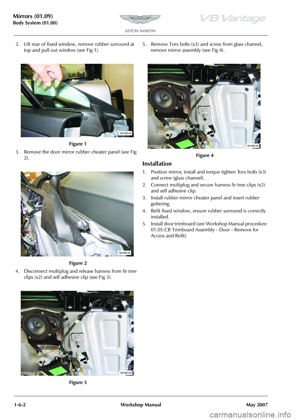
2. Lift rear of fixed window, remove rubber surround at
top and pull out window (see Fig 1).
3. Remove the door mirror rubber cheater panel (see Fig 2).
4. Disconnect multiplug and release harness from fir tree clips (x2) and self adhesive clip (see Fig 3). 5. Remove Torx bolts (x3) and screw from glass channel,
remove mirror assembly (see Fig 4).
Installation
1. Position mirror, install and to rque tighten Torx bolts (x3)
and screw (glass channel).
2. Connect multiplug and secure harness fir tree clips (x2) and self adhesive clip.
3. Install rubber mirror cheater panel and insert rubber guttering.
4. Refit fixed window, ensure rubber surround is correctly installed.
5. Install door trimboard (see Workshop Manual procedure 01.05.CB Trimboard Assembly - Door - Remove for
Access and Refit).
Figure 1
Figure 2
Figure 3
A0108145
A0108144
A0108143
Figure 4
A0108143