diagram AUDI A4 1996 B5 / 1.G APB Engine Electronic Engine Power Control Checking Workshop Manual
[x] Cancel search | Manufacturer: AUDI, Model Year: 1996, Model line: A4, Model: AUDI A4 1996 B5 / 1.GPages: 39, PDF Size: 0.16 MB
Page 5 of 39

24-143
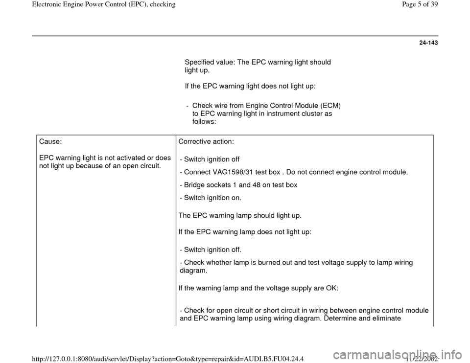
Specified value: The EPC warning light should
light up.
If the EPC warning light does not light up:
- Check wire from Engine Control Module (ECM)
to EPC warning light in instrument cluster as
follows: Cause:
EPC warning light is not activated or does
not light up because of an open circuit. Corrective action:
The EPC warning lamp should light up.
If the EPC warning lamp does not light up:
If the warning lamp and the voltage supply are OK: - Switch ignition off
- Connect VAG1598/31 test box . Do not connect engine control module.
- Bridge sockets 1 and 48 on test box
- Switch ignition on.
- Switch ignition off.
- Check whether lamp is burned out and test voltage supply to lamp wiring
diagram.
- Check for open circuit or short circuit in wiring between engine control module
and EPC warning lamp using wiring diagram. Determine and eliminate
Pa
ge 5 of 39 Electronic En
gine Power Control
(EPC
), checkin
g
11/22/2002 htt
p://127.0.0.1:8080/audi/servlet/Dis
play?action=Goto&t
yp
e=re
pair&id=AUDI.B5.FU04.24.4
Page 7 of 39

24-144
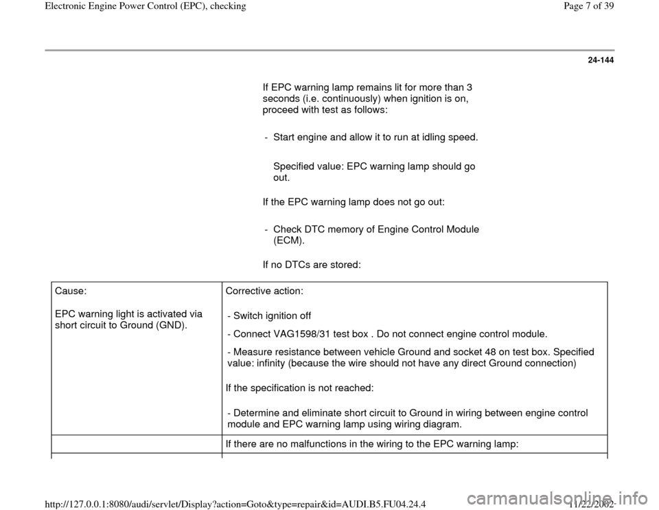
If EPC warning lamp remains lit for more than 3
seconds (i.e. continuously) when ignition is on,
proceed with test as follows:
- Start engine and allow it to run at idling speed.
Specified value: EPC warning lamp should go
out.
If the EPC warning lamp does not go out:
- Check DTC memory of Engine Control Module
(ECM).
If no DTCs are stored: Cause:
EPC warning light is activated via
short circuit to Ground (GND). Corrective action:
If the specification is not reached: - Switch ignition off
- Connect VAG1598/31 test box . Do not connect engine control module.
- Measure resistance between vehicle Ground and socket 48 on test box. Specified
value: infinity (because the wire should not have any direct Ground connection)
- Determine and eliminate short circuit to Ground in wiring between engine control
module and EPC warning lamp using wiring diagram.
If there are no malfunctions in the wiring to the EPC warning lamp:
Pa
ge 7 of 39 Electronic En
gine Power Control
(EPC
), checkin
g
11/22/2002 htt
p://127.0.0.1:8080/audi/servlet/Dis
play?action=Goto&t
yp
e=re
pair&id=AUDI.B5.FU04.24.4
Page 22 of 39

24-155
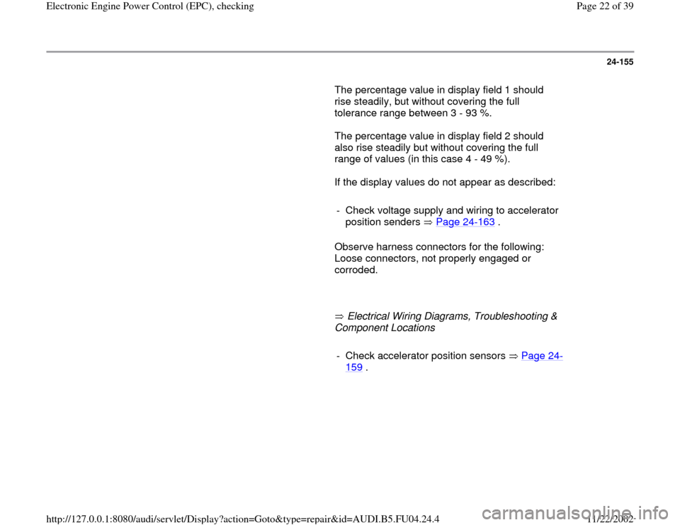
The percentage value in display field 1 should
rise steadily, but without covering the full
tolerance range between 3 - 93 %.
The percentage value in display field 2 should
also rise steadily but without covering the full
range of values (in this case 4 - 49 %).
If the display values do not appear as described:
- Check voltage supply and wiring to accelerator
position senders Page 24
-163
.
Observe harness connectors for the following:
Loose connectors, not properly engaged or
corroded.
Electrical Wiring Diagrams, Troubleshooting &
Component Locations
- Check accelerator position sensors Page 24
-
159
.
Pa
ge 22 of 39 Electronic En
gine Power Control
(EPC
), checkin
g
11/22/2002 htt
p://127.0.0.1:8080/audi/servlet/Dis
play?action=Goto&t
yp
e=re
pair&id=AUDI.B5.FU04.24.4
Page 25 of 39

24-158
Checking wiring for voltage, signal and
activation
- Connect VAG1598/31 test box to wiring harness
for engine control module. Do not connect to the
engine control module itself Page 24
-20
.
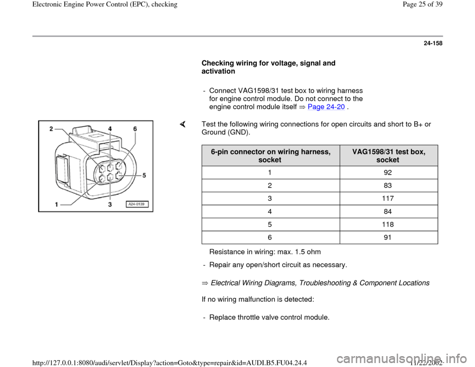
Test the following wiring connections for open circuits and short to B+ or
Ground (GND).
Electrical Wiring Diagrams, Troubleshooting & Component Locations
If no wiring malfunction is detected:
6-pin connector on wiring harness,
socket
VAG1598/31 test box,
socket
1 92
2 83
3 117
4 84
5 118
6 91
Resistance in wiring: max. 1.5 ohm
- Repair any open/short circuit as necessary.- Replace throttle valve control module.
Pa
ge 25 of 39 Electronic En
gine Power Control
(EPC
), checkin
g
11/22/2002 htt
p://127.0.0.1:8080/audi/servlet/Dis
play?action=Goto&t
yp
e=re
pair&id=AUDI.B5.FU04.24.4