AUDI A4 1996 B5 / 1.G AWM Engine Additional Signals Checking Workshop Manual
Manufacturer: AUDI, Model Year: 1996,
Model line: A4,
Model: AUDI A4 1996 B5 / 1.G
Pages: 25, PDF Size: 0.13 MB
AUDI A4 1996 B5 / 1.G AWM Engine Additional Signals Checking Workshop Manual
A4 1996 B5 / 1.G
AUDI
AUDI
https://www.carmanualsonline.info/img/6/1086/w960_1086-0.png
AUDI A4 1996 B5 / 1.G AWM Engine Additional Signals Checking Workshop Manual
Trending: cooling, ignition, air condition, wiring diagram, lock, airbag, wiring
Page 1 of 25
24-163
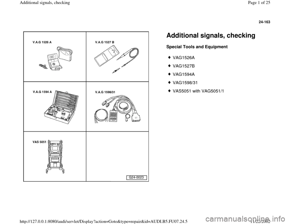
Additional signals, checking Special Tools and Equipment
VAG1526A
VAG1527B
VAG1594A
VAG1598/31
VAS5051 with VAG5051/1
Pa
ge 1 of 25 Additional si
gnals, checkin
g
11/22/2002 htt
p://127.0.0.1:8080/audi/servlet/Dis
play?action=Goto&t
yp
e=re
pair&id=AUDI.B5.FU07.24.5
Page 2 of 25
24-164
Engine speed signal, checking
Note:
The engine speed signal is output at terminal 37
of the Engine Control Module (ECM). The signal
is used, among other things, for RPM display in
the instrument cluster.
- Connect VAG1598/31 test box at wiring harness
to Engine Control Module (ECM), do not connect
ECM Page 24
-19
.
- Check the following wire connection for open
circuit and short circuit to Ground (GND) and B+:
Test box
VAG1598/31
Socket
Instrument cluster
Terminal
37 Electrical Wiring Diagrams,
Troubleshooting & Component
Locations
- Repair open circuit or short circuit if
necessary.
Pa
ge 2 of 25 Additional si
gnals, checkin
g
11/22/2002 htt
p://127.0.0.1:8080/audi/servlet/Dis
play?action=Goto&t
yp
e=re
pair&id=AUDI.B5.FU07.24.5
Page 3 of 25
24-165
Vehicle speed signal, checking
Notes:
The vehicle speed signal is generated by the
speedometer Vehicle Speed Sensor (VSS) -
G22- (at transmission) and is processed in the
instrument cluster.
The processed signal enters at terminal 54 of
the ECM and is used for idle stabilization and
tip-in shock reduction during shifting.
Test requirement:
Function and display of speedometer OK.
Troubleshooting:
Repair Manual, Electrical Equipment, Repair
Group 90; Instrument cluster; Speed signal, checking
Test sequence
WARNING!
To reduce the risk of accident during road
tests, always observe safety precautions
Page 24
-1 .
Pa
ge 3 of 25 Additional si
gnals, checkin
g
11/22/2002 htt
p://127.0.0.1:8080/audi/servlet/Dis
play?action=Goto&t
yp
e=re
pair&id=AUDI.B5.FU07.24.5
Page 4 of 25
- Connect VAS5051 tester Page 01
-7 and
select vehicle system "01 - Engine electronics".
Engine must run at idle for this.
Pa
ge 4 of 25 Additional si
gnals, checkin
g
11/22/2002 htt
p://127.0.0.1:8080/audi/servlet/Dis
play?action=Goto&t
yp
e=re
pair&id=AUDI.B5.FU07.24.5
Page 5 of 25
24-166
Display on VAS5051:
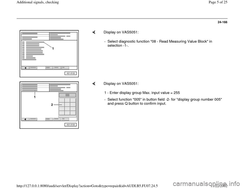
- Select diagnostic function "08 - Read Measuring Value Block" in
selection -1-.
Display on VAS5051:
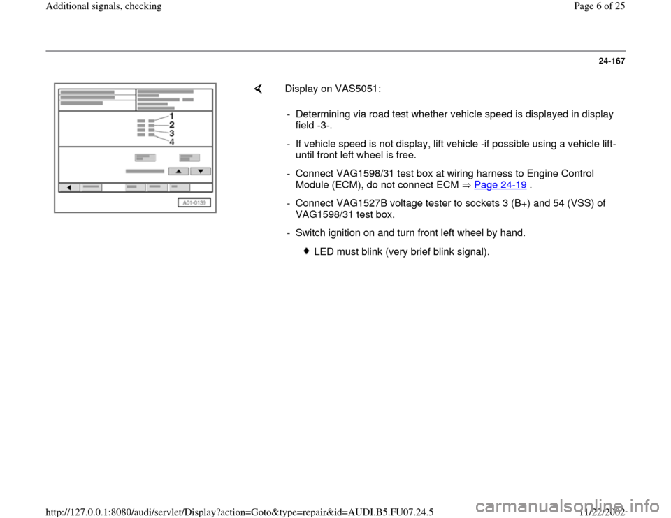
1 - Enter display group Max. input value = 255
- Select function "005" in button field -2- for "display group number 005"
and press Q button to confirm input.
Pa
ge 5 of 25 Additional si
gnals, checkin
g
11/22/2002 htt
p://127.0.0.1:8080/audi/servlet/Dis
play?action=Goto&t
yp
e=re
pair&id=AUDI.B5.FU07.24.5
Page 6 of 25
24-167
Display on VAS5051:
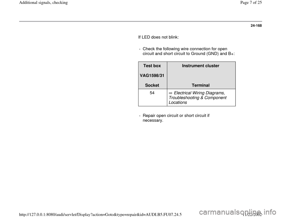
- Determining via road test whether vehicle speed is displayed in display
field -3-.
- If vehicle speed is not display, lift vehicle -if possible using a vehicle lift-
until front left wheel is free.
- Connect VAG1598/31 test box at wiring harness to Engine Control
Module (ECM), do not connect ECM Page 24
-19
.
- Connect VAG1527B voltage tester to sockets 3 (B+) and 54 (VSS) of
VAG1598/31 test box.
- Switch ignition on and turn front left wheel by hand.
LED must blink (very brief blink signal).
Pa
ge 6 of 25 Additional si
gnals, checkin
g
11/22/2002 htt
p://127.0.0.1:8080/audi/servlet/Dis
play?action=Goto&t
yp
e=re
pair&id=AUDI.B5.FU07.24.5
Page 7 of 25
24-168
If LED does not blink:
- Check the following wire connection for open
circuit and short circuit to Ground (GND) and B+:
Test box
VAG1598/31
Socket
Instrument cluster
Terminal
54 Electrical Wiring Diagrams,
Troubleshooting & Component
Locations
- Repair open circuit or short circuit if
necessary.
Pa
ge 7 of 25 Additional si
gnals, checkin
g
11/22/2002 htt
p://127.0.0.1:8080/audi/servlet/Dis
play?action=Goto&t
yp
e=re
pair&id=AUDI.B5.FU07.24.5
Page 8 of 25
24-169
A/C compressor shut-off, checking
Notes:
The A/C compressor signal communicates to
the ECM that the compressor will be switched
on in 140 ms.
The Engine Control Module (ECM) can switch
off the A/C compressor via the same wire
connection.
Engine Control Module (ECM) switches off A/C
compressor:
-- during hard acceleration (Wide Open
Throttle 1st gear)
-- in emergency mode (emergency
operation)
-- after initiating basic setting (function 04)
Pa
ge 8 of 25 Additional si
gnals, checkin
g
11/22/2002 htt
p://127.0.0.1:8080/audi/servlet/Dis
play?action=Goto&t
yp
e=re
pair&id=AUDI.B5.FU07.24.5
Page 9 of 25
24-170
Test requirements:
A/C system OK
No DTCs in DTC memory of Engine Control
Module (ECM).
Vehicle at room temperature (warmer than
+15 C).
Test sequence
- Connect VAS5051 tester Page 01
-7 and
select vehicle system "01 - Engine electronics".
Engine must run at idle for this.
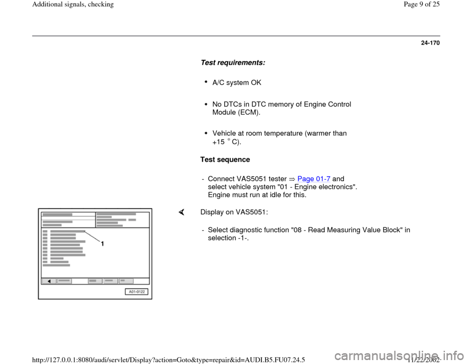
Display on VAS5051:
- Select diagnostic function "08 - Read Measuring Value Block" in
selection -1-.
Pa
ge 9 of 25 Additional si
gnals, checkin
g
11/22/2002 htt
p://127.0.0.1:8080/audi/servlet/Dis
play?action=Goto&t
yp
e=re
pair&id=AUDI.B5.FU07.24.5
Page 10 of 25
24-171
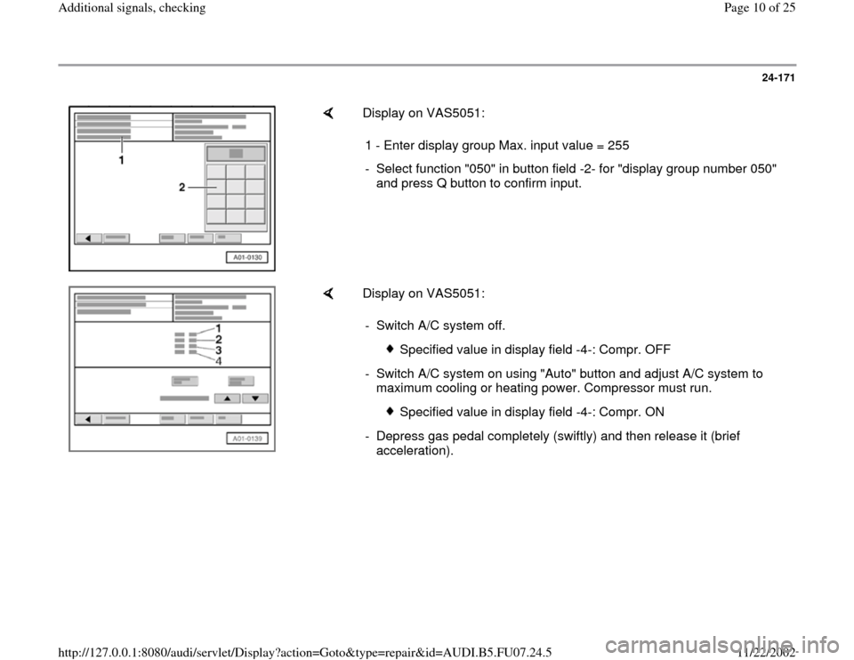
Display on VAS5051:
1 - Enter display group Max. input value = 255
- Select function "050" in button field -2- for "display group number 050"
and press Q button to confirm input.
Display on VAS5051:
- Switch A/C system off.
Specified value in display field -4-: Compr. OFF
- Switch A/C system on using "Auto" button and adjust A/C system to
maximum cooling or heating power. Compressor must run.
Specified value in display field -4-: Compr. ON
- Depress gas pedal completely (swiftly) and then release it (brief
acceleration).
Pa
ge 10 of 25 Additional si
gnals, checkin
g
11/22/2002 htt
p://127.0.0.1:8080/audi/servlet/Dis
play?action=Goto&t
yp
e=re
pair&id=AUDI.B5.FU07.24.5
Trending: manual transmission, heating, fuel, ignition, torque, air conditioning, wheel
