AUDI A4 1997 B5 / 1.G AWM Engine Valve Gear Service Owner's Guide
Manufacturer: AUDI, Model Year: 1997,
Model line: A4,
Model: AUDI A4 1997 B5 / 1.G
Pages: 58, PDF Size: 1.06 MB
AUDI A4 1997 B5 / 1.G AWM Engine Valve Gear Service Owner's Guide
A4 1997 B5 / 1.G
AUDI
AUDI
https://www.carmanualsonline.info/img/6/945/w960_945-0.png
AUDI A4 1997 B5 / 1.G AWM Engine Valve Gear Service Owner's Guide
Trending: oil filter, seats, torque, oil, coolant temperature, engine coolant, sensor
Page 31 of 58
15-66
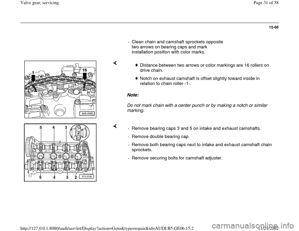
- Clean chain and camshaft sprockets opposite
two arrows on bearing caps and mark
installation position with color marks.
Note:
Do not mark chain with a center punch or by making a notch or similar
marking.
Distance between two arrows or color markings are 16 rollers on
drive chain.
Notch on exhaust camshaft is offset slightly toward inside in
relation to chain roller -1-.
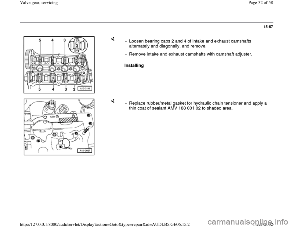
- Remove bearing caps 3 and 5 on intake and exhaust camshafts.
- Remove double bearing cap.
- Remove both bearing caps next to intake and exhaust camshaft chain
sprockets.
- Remove securing bolts for camshaft adjuster.
Pa
ge 31 of 58 Valve
gear, servicin
g
11/21/2002 htt
p://127.0.0.1:8080/audi/servlet/Dis
play?action=Goto&t
yp
e=re
pair&id=AUDI.B5.GE06.15.2
Page 32 of 58
15-67
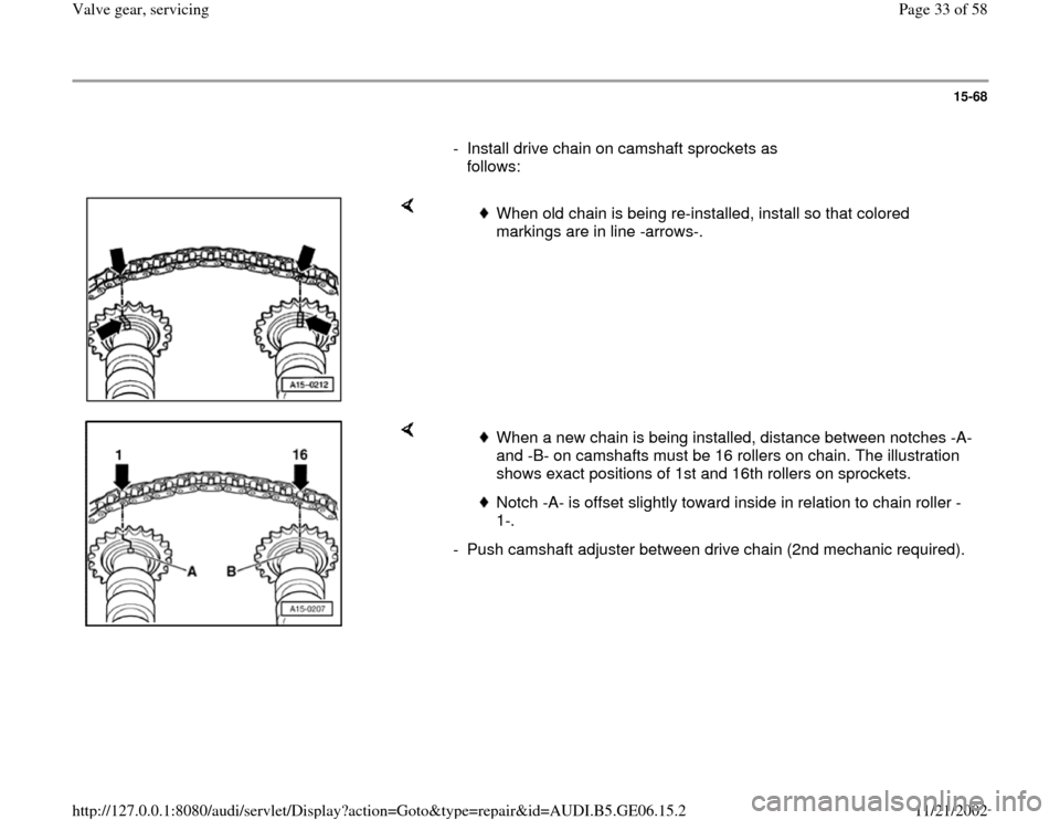
Installing - Loosen bearing caps 2 and 4 of intake and exhaust camshafts
alternately and diagonally, and remove.
- Remove intake and exhaust camshafts with camshaft adjuster.
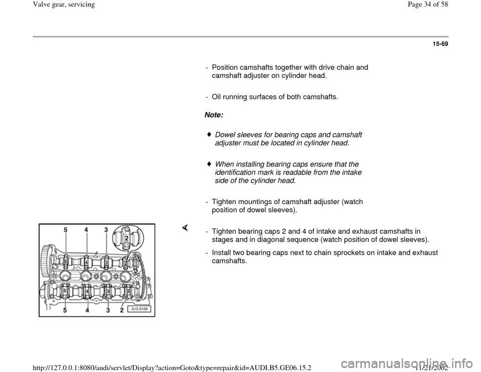
- Replace rubber/metal gasket for hydraulic chain tensioner and apply a
thin coat of sealant AMV 188 001 02 to shaded area.
Pa
ge 32 of 58 Valve
gear, servicin
g
11/21/2002 htt
p://127.0.0.1:8080/audi/servlet/Dis
play?action=Goto&t
yp
e=re
pair&id=AUDI.B5.GE06.15.2
Page 33 of 58
15-68
- Install drive chain on camshaft sprockets as
follows:
When old chain is being re-installed, install so that colored
markings are in line -arrows-.
When a new chain is being installed, distance between notches -A-
and -B- on camshafts must be 16 rollers on chain. The illustration
shows exact positions of 1st and 16th rollers on sprockets.
Notch -A- is offset slightly toward inside in relation to chain roller -
1-.
- Push camshaft adjuster between drive chain (2nd mechanic required).
Pa
ge 33 of 58 Valve
gear, servicin
g
11/21/2002 htt
p://127.0.0.1:8080/audi/servlet/Dis
play?action=Goto&t
yp
e=re
pair&id=AUDI.B5.GE06.15.2
Page 34 of 58
15-69
- Position camshafts together with drive chain and
camshaft adjuster on cylinder head.
- Oil running surfaces of both camshafts.
Note:
Dowel sleeves for bearing caps and camshaft
adjuster must be located in cylinder head.
When installing bearing caps ensure that the
identification mark is readable from the intake
side of the cylinder head.
- Tighten mountings of camshaft adjuster (watch
position of dowel sleeves).
- Tighten bearing caps 2 and 4 of intake and exhaust camshafts in
stages and in diagonal sequence (watch position of dowel sleeves).
- Install two bearing caps next to chain sprockets on intake and exhaust
camshafts.
Pa
ge 34 of 58 Valve
gear, servicin
g
11/21/2002 htt
p://127.0.0.1:8080/audi/servlet/Dis
play?action=Goto&t
yp
e=re
pair&id=AUDI.B5.GE06.15.2
Page 35 of 58
15-70
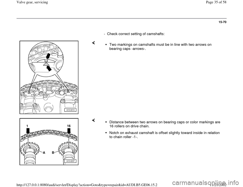
- Check correct setting of camshafts:
Two markings on camshafts must be in line with two arrows on
bearing caps -arrows-.
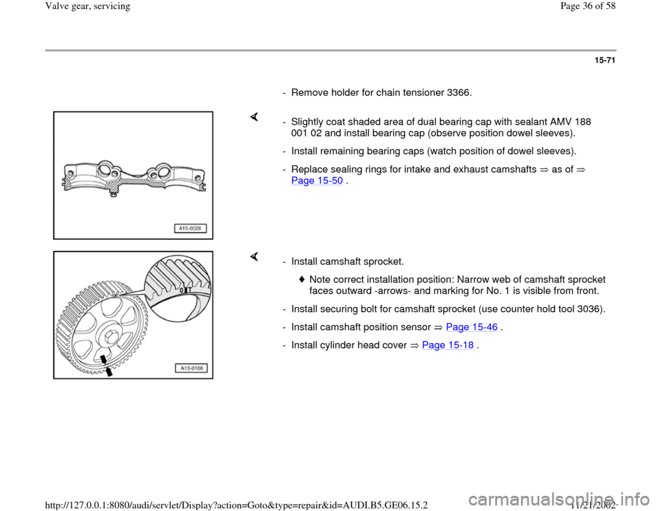
Distance between two arrows on bearing caps or color markings are
16 rollers on drive chain. Notch on exhaust camshaft is offset slightly toward inside in relation
to chain roller -1-.
Pa
ge 35 of 58 Valve
gear, servicin
g
11/21/2002 htt
p://127.0.0.1:8080/audi/servlet/Dis
play?action=Goto&t
yp
e=re
pair&id=AUDI.B5.GE06.15.2
Page 36 of 58
15-71
- Remove holder for chain tensioner 3366.
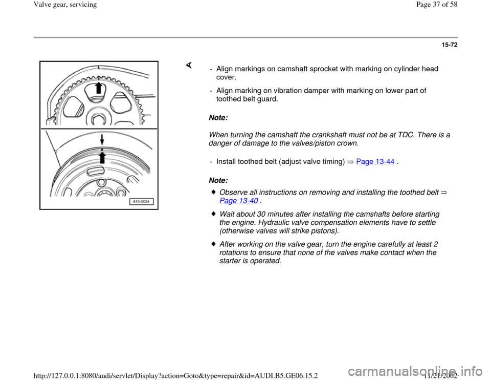
- Slightly coat shaded area of dual bearing cap with sealant AMV 188
001 02 and install bearing cap (observe position dowel sleeves).
- Install remaining bearing caps (watch position of dowel sleeves).
- Replace sealing rings for intake and exhaust camshafts as of
Page 15
-50
.
- Install camshaft sprocket.
Note correct installation position: Narrow web of camshaft sprocket
faces outward -arrows- and marking for No. 1 is visible from front.
- Install securing bolt for camshaft sprocket (use counter hold tool 3036).
- Install camshaft position sensor Page 15
-46
.
- Install cylinder head cover Page 15
-18
.
Pa
ge 36 of 58 Valve
gear, servicin
g
11/21/2002 htt
p://127.0.0.1:8080/audi/servlet/Dis
play?action=Goto&t
yp
e=re
pair&id=AUDI.B5.GE06.15.2
Page 37 of 58
15-72
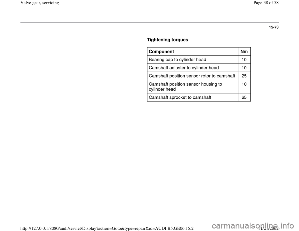
Note:
When turning the camshaft the crankshaft must not be at TDC. There is a
danger of damage to the valves/piston crown.
Note: - Align markings on camshaft sprocket with marking on cylinder head
cover.
- Align marking on vibration damper with marking on lower part of
toothed belt guard.
- Install toothed belt (adjust valve timing) Page 13
-44
.
Observe all instructions on removing and installing the toothed belt
Page 13
-40
.
Wait about 30 minutes after installing the camshafts before starting
the engine. Hydraulic valve compensation elements have to settle
(otherwise valves will strike pistons). After working on the valve gear, turn the engine carefully at least 2
rotations to ensure that none of the valves make contact when the
starter is operated.
Pa
ge 37 of 58 Valve
gear, servicin
g
11/21/2002 htt
p://127.0.0.1:8080/audi/servlet/Dis
play?action=Goto&t
yp
e=re
pair&id=AUDI.B5.GE06.15.2
Page 38 of 58
15-73
Tightening torques
Component
Nm
Bearing cap to cylinder head 10
Camshaft adjuster to cylinder head 10
Camshaft position sensor rotor to camshaft 25
Camshaft position sensor housing to
cylinder head 10
Camshaft sprocket to camshaft 65
Pa
ge 38 of 58 Valve
gear, servicin
g
11/21/2002 htt
p://127.0.0.1:8080/audi/servlet/Dis
play?action=Goto&t
yp
e=re
pair&id=AUDI.B5.GE06.15.2
Page 39 of 58
15-74
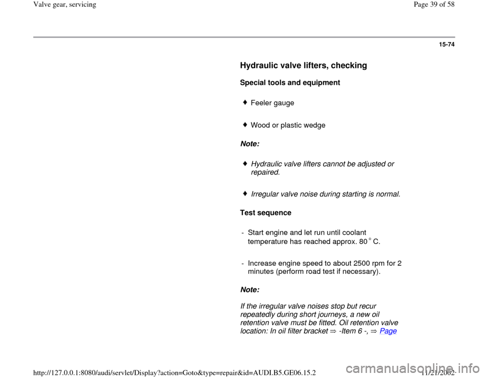
Hydraulic valve lifters, checking
Special tools and equipment
Feeler gauge
Wood or plastic wedge
Note:
Hydraulic valve lifters cannot be adjusted or
repaired.
Irregular valve noise during starting is normal.
Test sequence
- Start engine and let run until coolant
temperature has reached approx. 80 C.
- Increase engine speed to about 2500 rpm for 2
minutes (perform road test if necessary).
Note:
If the irregular valve noises stop but recur
repeatedly during short journeys, a new oil
retention valve must be fitted. Oil retention valve
location: In oil filter bracket -Item 6 -, Page
Pa
ge 39 of 58 Valve
gear, servicin
g
11/21/2002 htt
p://127.0.0.1:8080/audi/servlet/Dis
play?action=Goto&t
yp
e=re
pair&id=AUDI.B5.GE06.15.2
Page 40 of 58
17
-7 .
Pa
ge 40 of 58 Valve
gear, servicin
g
11/21/2002 htt
p://127.0.0.1:8080/audi/servlet/Dis
play?action=Goto&t
yp
e=re
pair&id=AUDI.B5.GE06.15.2
Trending: air filter, Valve guides, timing belt, torque, ignition, oil filter, light
