AUDI A6 1998 C5 / 2.G AEB ATW Engines Cylinder Head Remove And Install User Guide
Manufacturer: AUDI, Model Year: 1998,
Model line: A6,
Model: AUDI A6 1998 C5 / 2.G
Pages: 35, PDF Size: 0.68 MB
AUDI A6 1998 C5 / 2.G AEB ATW Engines Cylinder Head Remove And Install User Guide
A6 1998 C5 / 2.G
AUDI
AUDI
https://www.carmanualsonline.info/img/6/949/w960_949-0.png
AUDI A6 1998 C5 / 2.G AEB ATW Engines Cylinder Head Remove And Install User Guide
Trending: check engine, brake, check oil, service, transmission, coolant temperature, lock
Page 11 of 35
15-12
Note:
For vehicles with automatic transmission, remove vacuum hose -2- from
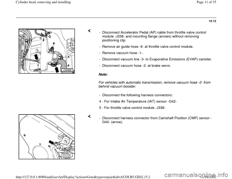
behind vacuum booster. - Disconnect Accelerator Pedal (AP) cable from throttle valve control
module -J338- and mounting flange (arrows) without removing
positioning clip.
- Remove air guide hose -6- at throttle valve control module.
- Remove vacuum hose -1-.
- Disconnect vacuum line -3- to Evaporative Emissions (EVAP) canister.
- Disconnect vacuum hose -2- at brake servo.
- Disconnect the following harness connectors:
4 - For Intake Air Temperature (IAT) sensor -G42-
5 - For throttle valve control module -J338-
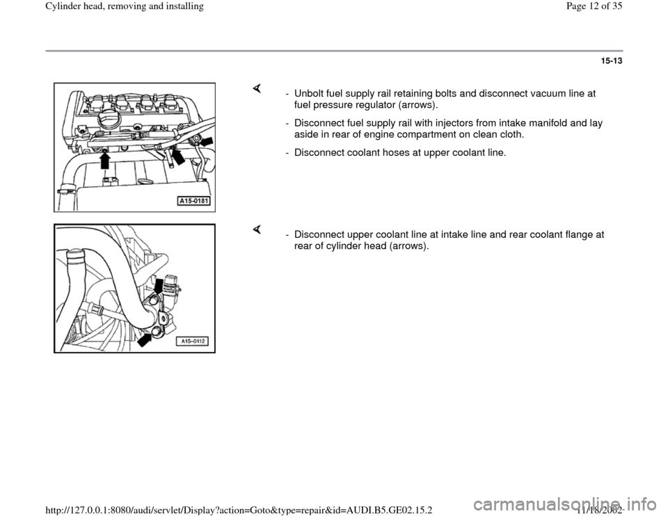
- Disconnect harness connector from Camshaft Position (CMP) sensor -
G40- (arrow).
Pa
ge 11 of 35 C
ylinder head, removin
g and installin
g
11/18/2002 htt
p://127.0.0.1:8080/audi/servlet/Dis
play?action=Goto&t
yp
e=re
pair&id=AUDI.B5.GE02.15.2
Page 12 of 35
15-13
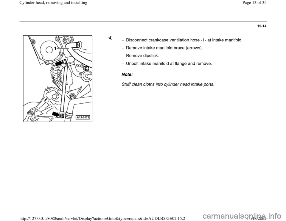
- Unbolt fuel supply rail retaining bolts and disconnect vacuum line at
fuel pressure regulator (arrows).
- Disconnect fuel supply rail with injectors from intake manifold and lay
aside in rear of engine compartment on clean cloth.
- Disconnect coolant hoses at upper coolant line.
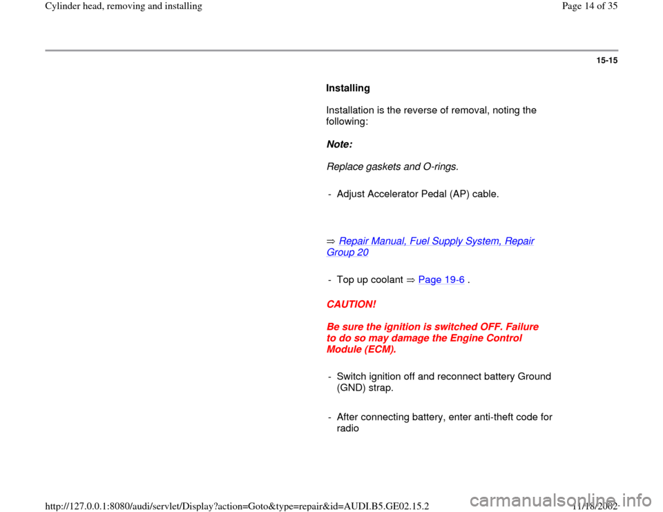
- Disconnect upper coolant line at intake line and rear coolant flange at
rear of cylinder head (arrows).
Pa
ge 12 of 35 C
ylinder head, removin
g and installin
g
11/18/2002 htt
p://127.0.0.1:8080/audi/servlet/Dis
play?action=Goto&t
yp
e=re
pair&id=AUDI.B5.GE02.15.2
Page 13 of 35
15-14
Note:
Stuff clean cloths into cylinder head intake ports. - Disconnect crankcase ventilation hose -1- at intake manifold.
- Remove intake manifold brace (arrows).
- Remove dipstick.
- Unbolt intake manifold at flange and remove.
Pa
ge 13 of 35 C
ylinder head, removin
g and installin
g
11/18/2002 htt
p://127.0.0.1:8080/audi/servlet/Dis
play?action=Goto&t
yp
e=re
pair&id=AUDI.B5.GE02.15.2
Page 14 of 35
15-15
Installing
Installation is the reverse of removal, noting the
following:
Note:
Replace gaskets and O-rings.
- Adjust Accelerator Pedal (AP) cable.
Repair Manual, Fuel Supply System, Repair
Group 20
- Top up coolant Page 19
-6 .
CAUTION!
Be sure the ignition is switched OFF. Failure
to do so may damage the Engine Control
Module (ECM).
- Switch ignition off and reconnect battery Ground
(GND) strap.
- After connecting battery, enter anti-theft code for
radio
Pa
ge 14 of 35 C
ylinder head, removin
g and installin
g
11/18/2002 htt
p://127.0.0.1:8080/audi/servlet/Dis
play?action=Goto&t
yp
e=re
pair&id=AUDI.B5.GE02.15.2
Page 15 of 35
Radio operating manual
- Fully close power windows to stop.
- Operate all power window switches again for at
least one second in "close" direction to activate
"one touch" opening/closing function.
- Set clock to correct time.
Pa
ge 15 of 35 C
ylinder head, removin
g and installin
g
11/18/2002 htt
p://127.0.0.1:8080/audi/servlet/Dis
play?action=Goto&t
yp
e=re
pair&id=AUDI.B5.GE02.15.2
Page 16 of 35
15-16
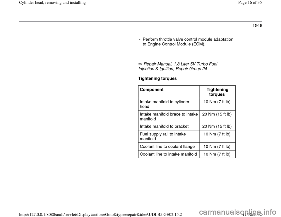
- Perform throttle valve control module adaptation
to Engine Control Module (ECM).
Repair Manual, 1.8 Liter 5V Turbo Fuel
Injection & Ignition, Repair Group 24
Tightening torques
Component
Tightening
torques
Intake manifold to cylinder
head 10 Nm (7 ft lb)
Intake manifold brace to intake
manifold 20 Nm (15 ft lb)
Intake manifold to bracket 20 Nm (15 ft lb)
Fuel supply rail to intake
manifold 10 Nm (7 ft lb)
Coolant line to coolant flange 10 Nm (7 ft lb)
Coolant line to intake manifold 10 Nm (7 ft lb)
Pa
ge 16 of 35 C
ylinder head, removin
g and installin
g
11/18/2002 htt
p://127.0.0.1:8080/audi/servlet/Dis
play?action=Goto&t
yp
e=re
pair&id=AUDI.B5.GE02.15.2
Page 17 of 35
15-17
Cylinder head cover, removing and
installing
Removing
- Remove engine covers.
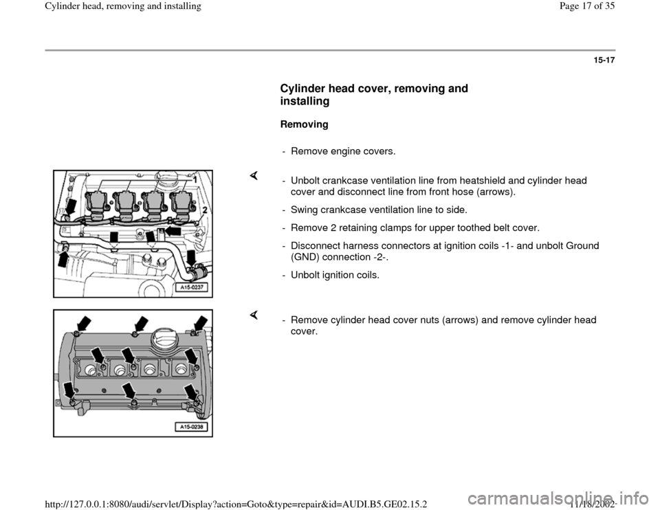
- Unbolt crankcase ventilation line from heatshield and cylinder head
cover and disconnect line from front hose (arrows).
- Swing crankcase ventilation line to side.
- Remove 2 retaining clamps for upper toothed belt cover.
- Disconnect harness connectors at ignition coils -1- and unbolt Ground
(GND) connection -2-.
- Unbolt ignition coils.
- Remove cylinder head cover nuts (arrows) and remove cylinder head
cover.
Pa
ge 17 of 35 C
ylinder head, removin
g and installin
g
11/18/2002 htt
p://127.0.0.1:8080/audi/servlet/Dis
play?action=Goto&t
yp
e=re
pair&id=AUDI.B5.GE02.15.2
Page 18 of 35
15-18
Installing
Installation is the reverse of removal, noting the
following:
Note:
Replace cylinder head cover gaskets if damaged.
CAUTION!
Part numbers are listed here for reference only. Always check with
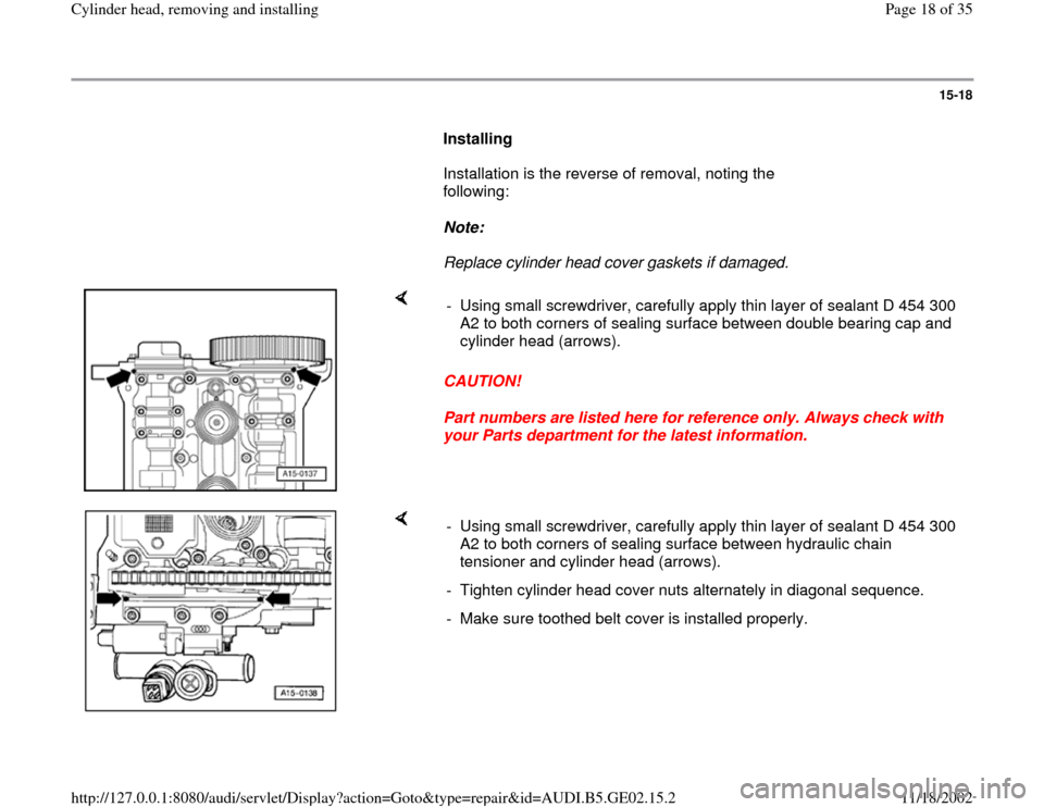
your Parts department for the latest information. - Using small screwdriver, carefully apply thin layer of sealant D 454 300
A2 to both corners of sealing surface between double bearing cap and
cylinder head (arrows).
- Using small screwdriver, carefully apply thin layer of sealant D 454 300
A2 to both corners of sealing surface between hydraulic chain
tensioner and cylinder head (arrows).
- Tighten cylinder head cover nuts alternately in diagonal sequence.
- Make sure toothed belt cover is installed properly.
Pa
ge 18 of 35 C
ylinder head, removin
g and installin
g
11/18/2002 htt
p://127.0.0.1:8080/audi/servlet/Dis
play?action=Goto&t
yp
e=re
pair&id=AUDI.B5.GE02.15.2
Page 19 of 35
15-19
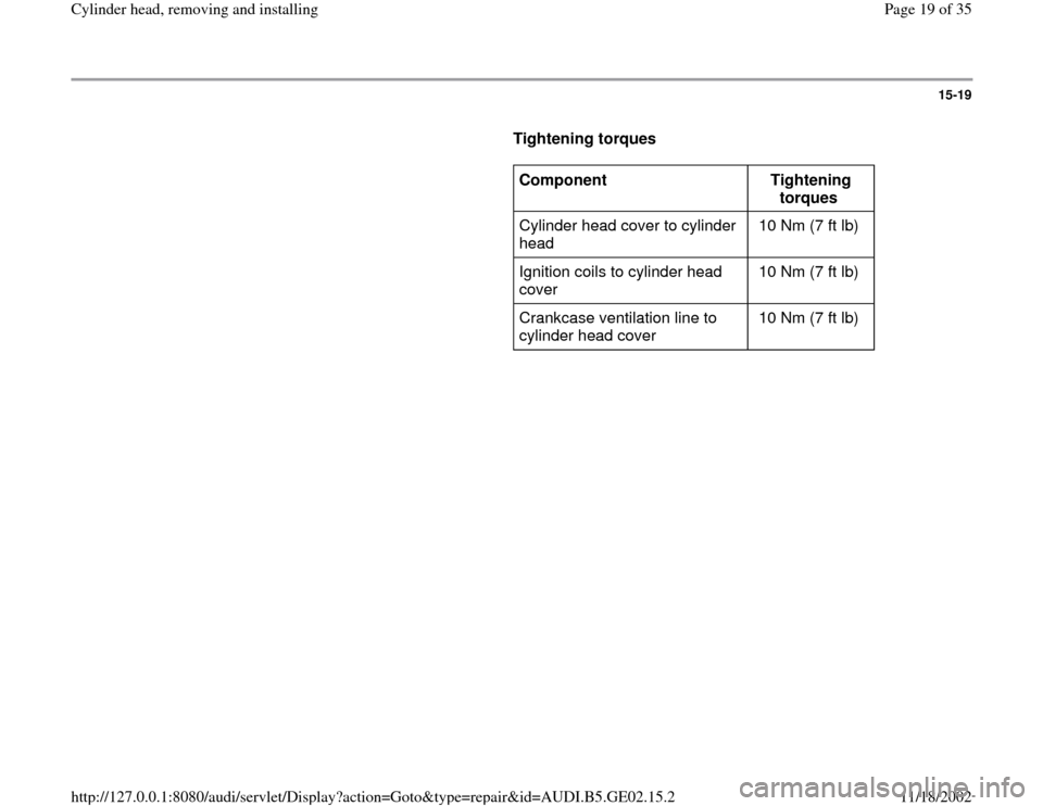
Tightening torques
Component
Tightening
torques
Cylinder head cover to cylinder
head 10 Nm (7 ft lb)
Ignition coils to cylinder head
cover 10 Nm (7 ft lb)
Crankcase ventilation line to
cylinder head cover 10 Nm (7 ft lb)
Pa
ge 19 of 35 C
ylinder head, removin
g and installin
g
11/18/2002 htt
p://127.0.0.1:8080/audi/servlet/Dis
play?action=Goto&t
yp
e=re
pair&id=AUDI.B5.GE02.15.2
Page 20 of 35
15-20
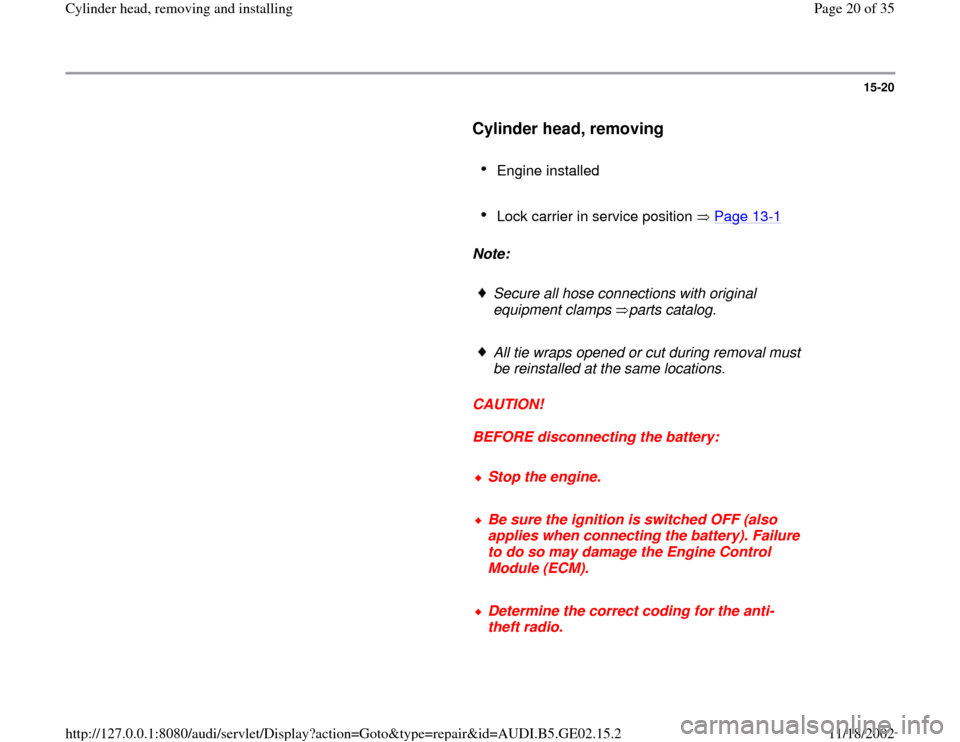
Cylinder head, removing
Engine installed
Lock carrier in service position Page 13
-1
Note:
Secure all hose connections with original
equipment clamps parts catalog.
All tie wraps opened or cut during removal must
be reinstalled at the same locations.
CAUTION!
BEFORE disconnecting the battery:
Stop the engine.
Be sure the ignition is switched OFF (also
applies when connecting the battery). Failure
to do so may damage the Engine Control
Module (ECM).
Determine the correct coding for the anti-
theft radio.
Pa
ge 20 of 35 C
ylinder head, removin
g and installin
g
11/18/2002 htt
p://127.0.0.1:8080/audi/servlet/Dis
play?action=Goto&t
yp
e=re
pair&id=AUDI.B5.GE02.15.2
Trending: CD changer, brake, remove seats, coolant, service, engine oil, fuel cap
