AUDI A8 2003 D3 / 2.G Technical Features Manual
Manufacturer: AUDI, Model Year: 2003, Model line: A8, Model: AUDI A8 2003 D3 / 2.GPages: 96, PDF Size: 5.51 MB
Page 51 of 96
Downloaded from www.Manualslib.com manuals search engine 51
4-level air suspension
The introduction of the Audi A8 ´03 is
accompanied by a system featuring new
technical details and functions. The major
differences with respect to the familiar Audi
allroad quattro
® system are as follows:
EDC instead of PDC damping
The control system makes allowance for the
currently applicable driving status. Wheel
movement (unsprung masses) and body
movement (sprung masses) are detected.
Various damping characteristic curves are
implemented within the scope of three
selectable programs (modes) and each
damper can be controlled individually.
Control concept
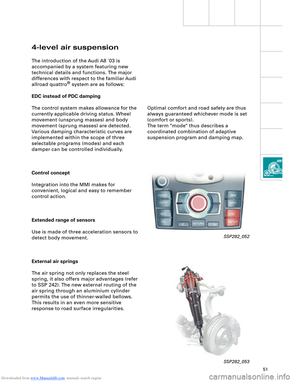
Integration into the MMI makes for
convenient, logical and easy to remember
control action.
Extended range of sensors
Use is made of three acceleration sensors to
detect body movement.
External air springs
The air spring not only replaces the steel
spring, it also offers major advantages (refer
to SSP 242). The new external routing of the
air spring through an aluminium cylinder
permits the use of thinner-walled bellows.
This results in an even more sensitive
response to road surface irregularities.
SSP282_052
SSP282_053
Optimal comfort and road safety are thus
always guaranteed whichever mode is set
(comfort or sports).
The term "mode" thus describes a
coordinated combination of adaptive
suspension program and damping map.
Page 52 of 96
Downloaded from www.Manualslib.com manuals search engine 52
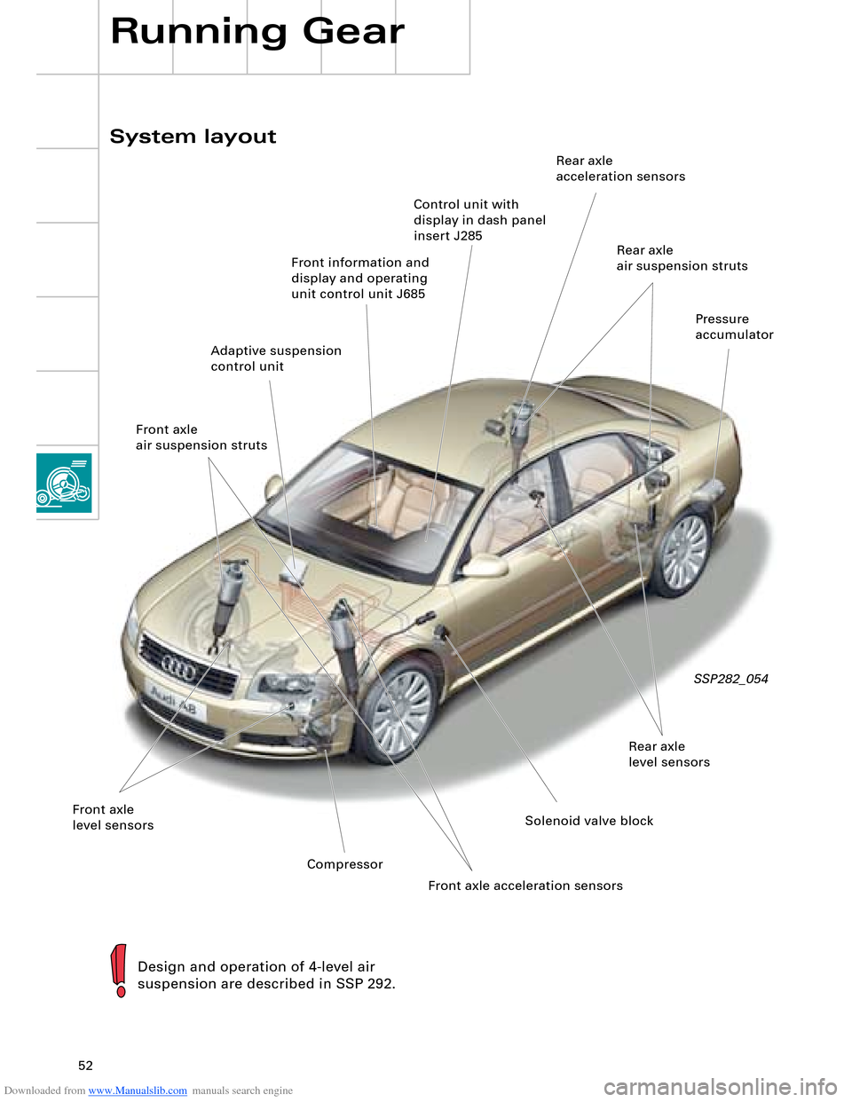
System layout
Running Gear
SSP282_054
Design and operation of 4-level air
suspension are described in SSP 292.
Front information and
display and operating
unit control unit J685
Front axle
level sensorsSolenoid valve blockRear axle
level sensorsPressure
accumulator
Adaptive suspension
control unitRear axle
air suspension struts Rear axle
acceleration sensors
CompressorControl unit with
display in dash panel
insert J285
Front axle
air suspension struts
Front axle acceleration sensors
Page 53 of 96
Downloaded from www.Manualslib.com manuals search engine 53
The following functions are provided by the
electric parking brake:
– Parking brake function
– Emergency braking function
– Holding function when driving off on a hill
– Brake pad wear indicator
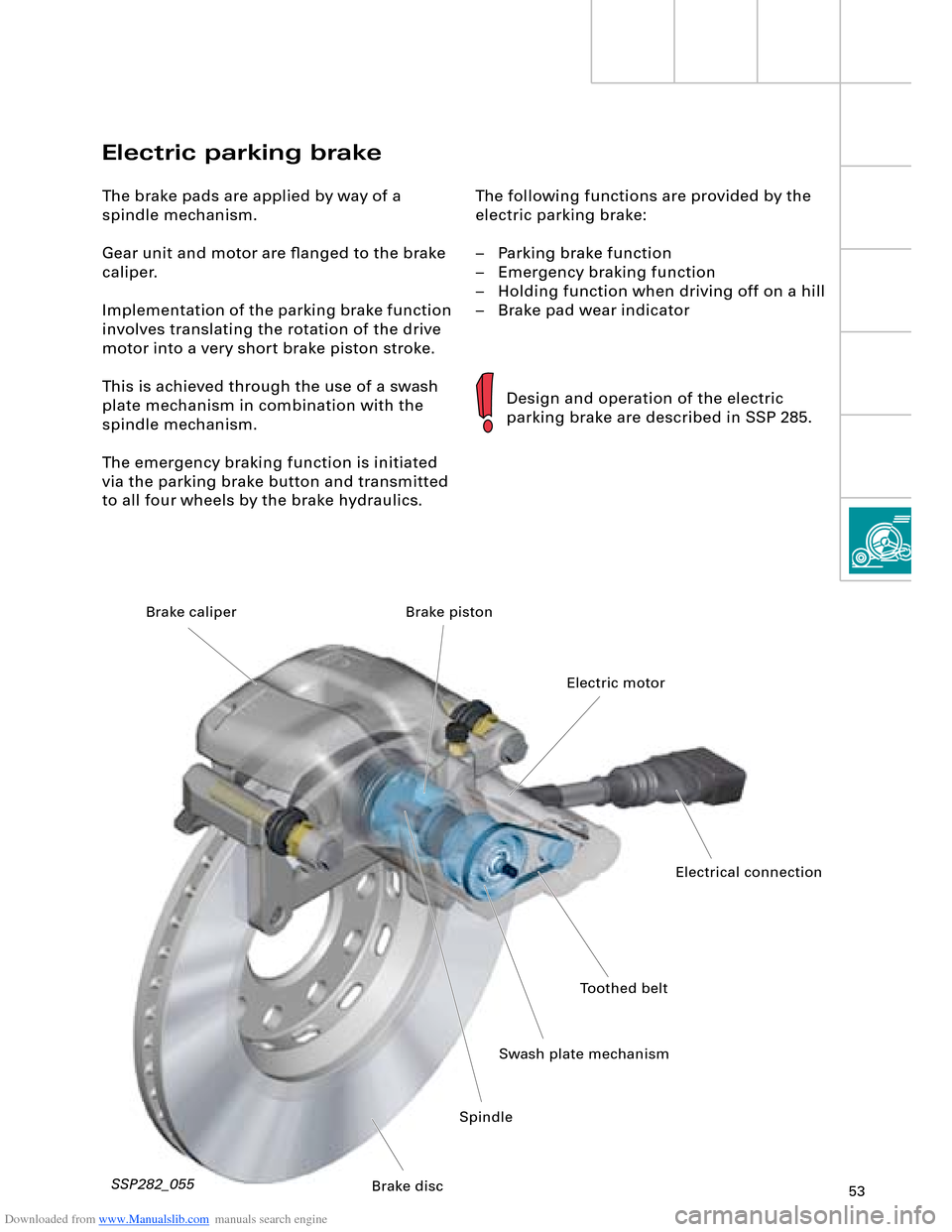
Electric parking brake
The brake pads are applied by way of a
spindle mechanism.
Gear unit and motor are flanged to the brake
caliper.
Implementation of the parking brake function
involves translating the rotation of the drive
motor into a very short brake piston stroke.
This is achieved through the use of a swash
plate mechanism in combination with the
spindle mechanism.
The emergency braking function is initiated
via the parking brake button and transmitted
to all four wheels by the brake hydraulics.
Design and operation of the electric
parking brake are described in SSP 285.
SSP282_055
Toothed belt
Swash plate mechanismElectric motor Brake piston
SpindleElectrical connection
Brake disc Brake caliper
Page 54 of 96
Downloaded from www.Manualslib.com manuals search engine 54
Driver convenience is further enhanced, as
fewer accelerator and brake pedal operations
are required. Speed restrictions and safety
factors are reliably observed and the flow of
traffic thus better regulated.
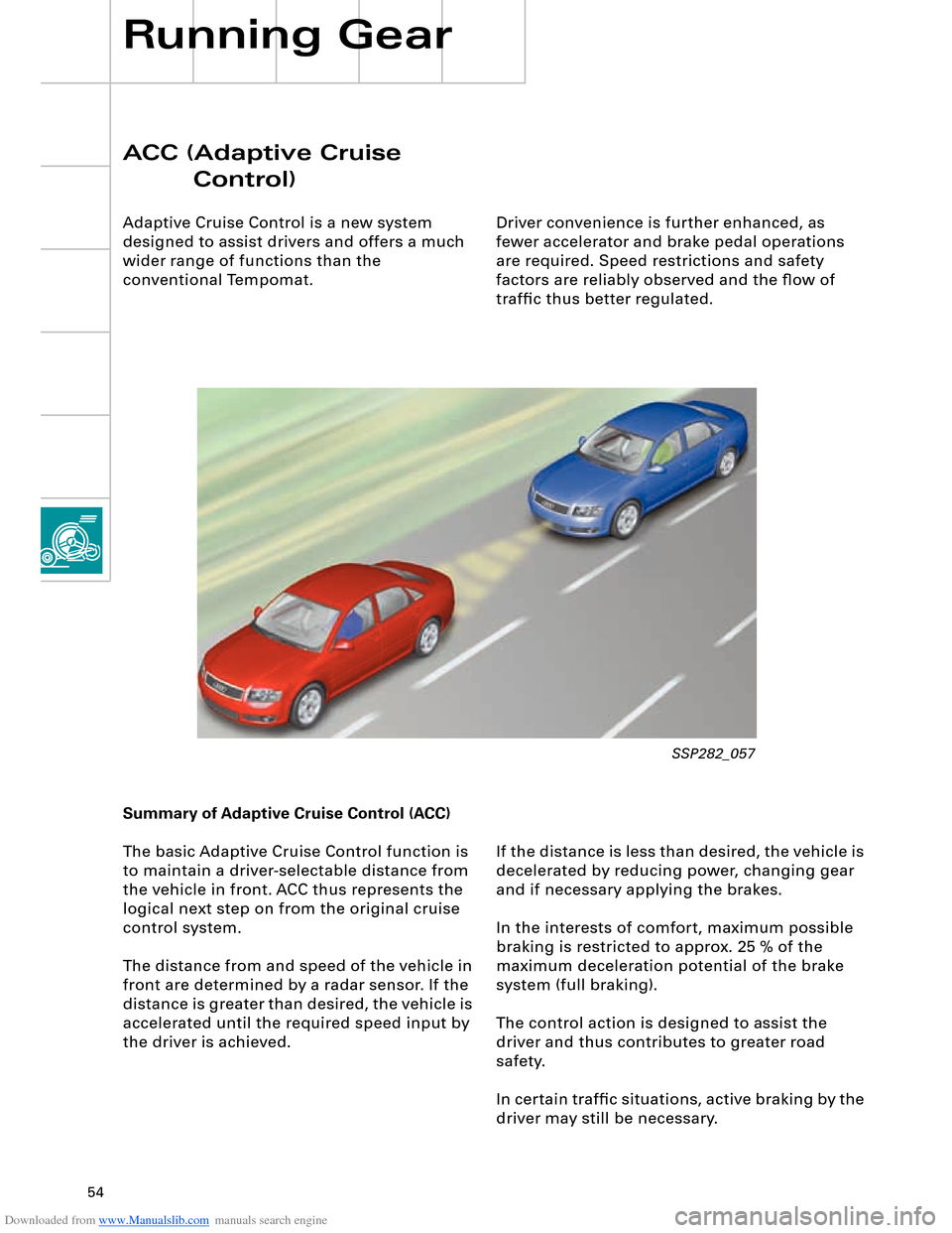
ACC (Adaptive Cruise
Control)
Adaptive Cruise Control is a new system
designed to assist drivers and offers a much
wider range of functions than the
conventional Tempomat.
Running Gear
If the distance is less than desired, the vehicle is
decelerated by reducing power, changing gear
and if necessary applying the brakes.
In the interests of comfort, maximum possible
braking is restricted to approx. 25 % of the
maximum deceleration potential of the brake
system (full braking).
The control action is designed to assist the
driver and thus contributes to greater road
safety.
In certain traffic situations, active braking by the
driver may still be necessary. Summary of Adaptive Cruise Control (ACC)
The basic Adaptive Cruise Control function is
to maintain a driver-selectable distance from
the vehicle in front. ACC thus represents the
logical next step on from the original cruise
control system.
The distance from and speed of the vehicle in
front are determined by a radar sensor. If the
distance is greater than desired, the vehicle is
accelerated until the required speed input by
the driver is achieved.
SSP282_057
Page 55 of 96
Downloaded from www.Manualslib.com manuals search engine 55
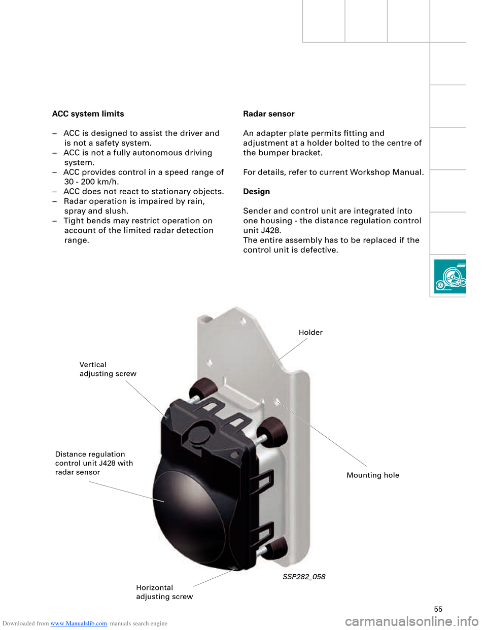
Radar sensor
An adapter plate permits fitting and
adjustment at a holder bolted to the centre of
the bumper bracket.
For details, refer to current Workshop Manual.
Design
Sender and control unit are integrated into
one housing - the distance regulation control
unit J428.
The entire assembly has to be replaced if the
control unit is defective. ACC system limits
– ACC is designed to assist the driver and
is not a safety system.
– ACC is not a fully autonomous driving
system.
– ACC provides control in a speed range of
30 - 200 km/h.
– ACC does not react to stationary objects.
– Radar operation is impaired by rain,
spray and slush.
– Tight bends may restrict operation on
account of the limited radar detection
range.
SSP282_058
Vertical
adjusting screwHolder
Distance regulation
control unit J428 with
radar sensor
Horizontal
adjusting screwMounting hole
Page 56 of 96
Downloaded from www.Manualslib.com manuals search engine 56
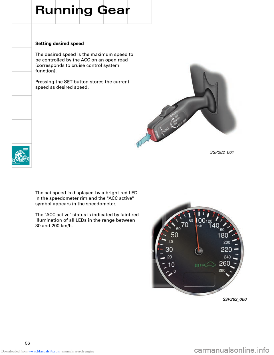
SSP282_061
Setting desired speed
The desired speed is the maximum speed to
be controlled by the ACC on an open road
(corresponds to cruise control system
function).
Pressing the SET button stores the current
speed as desired speed.
Running Gear
The set speed is displayed by a bright red LED
in the speedometer rim and the "ACC active"
symbol appears in the speedometer.
The "ACC active" status is indicated by faint red
illumination of all LEDs in the range between
30 and 200 km/h.
SSP282_060
Page 57 of 96
Downloaded from www.Manualslib.com manuals search engine 57
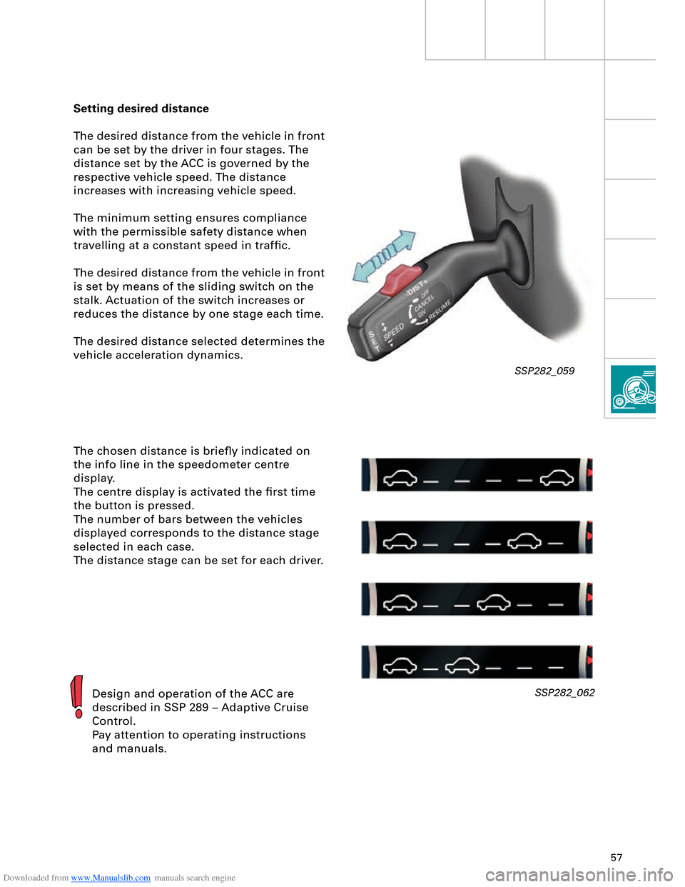
Setting desired distance
The desired distance from the vehicle in front
can be set by the driver in four stages. The
distance set by the ACC is governed by the
respective vehicle speed. The distance
increases with increasing vehicle speed.
The minimum setting ensures compliance
with the permissible safety distance when
travelling at a constant speed in traffic.
The desired distance from the vehicle in front
is set by means of the sliding switch on the
stalk. Actuation of the switch increases or
reduces the distance by one stage each time.
The desired distance selected determines the
vehicle acceleration dynamics.
The chosen distance is briefly indicated on
the info line in the speedometer centre
display.
The centre display is activated the first time
the button is pressed.
The number of bars between the vehicles
displayed corresponds to the distance stage
selected in each case.
The distance stage can be set for each driver.
Design and operation of the ACC are
described in SSP 289 – Adaptive Cruise
Control.
Pay attention to operating instructions
and manuals.SSP282_062
SSP282_059
Page 58 of 96
Downloaded from www.Manualslib.com manuals search engine 58
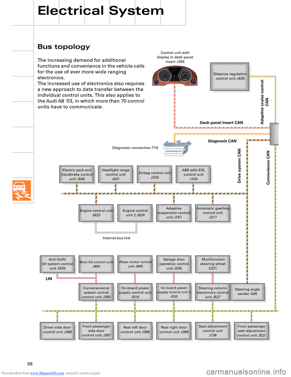
Bus topology
Electrical System
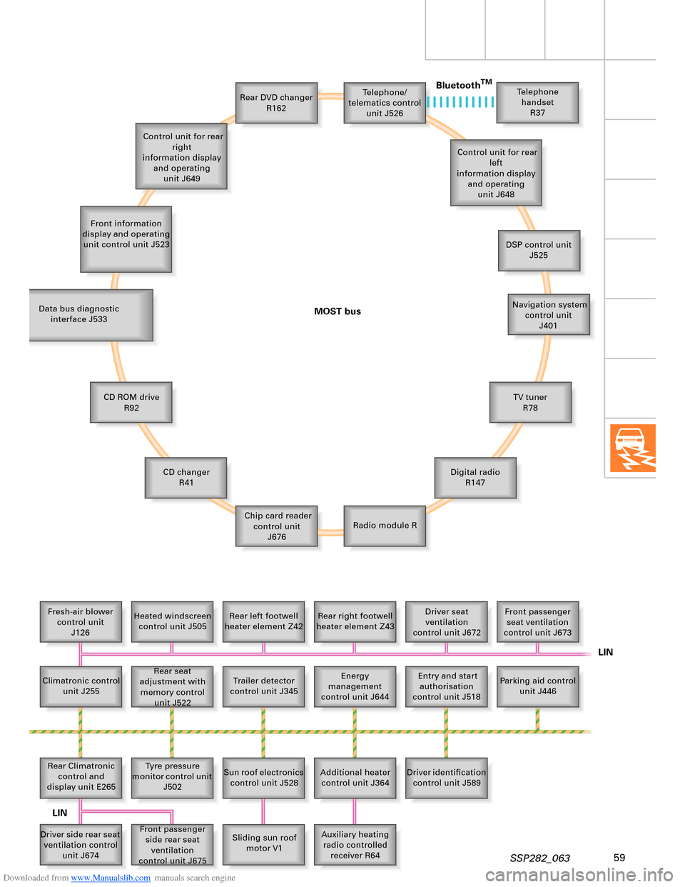
The increasing demand for additional
functions and convenience in the vehicle calls
for the use of ever more wide ranging
electronics.
The increased use of electronics also requires
a new approach to data transfer between the
individual control units. This also applies to
the Audi A8 ´03, in which more than 70 control
units have to communicate.
Distance regulation
control unit J428
Electric park and
handbrake control
unit J540Headlight range
control unit
J431Airbag control unit
J234ABS with EDL
control unit
J104
Engine control unit
J623Adaptive
suspension control
unit J197 Engine control
unit 2 J624Automatic gearbox
control unit
J217
Anti-theft/
tilt system control
unit J529
Boot lid control unit
J605Wiper motor control
unit J400Garage door
operation control
unit J530 Multifunction
steering wheel
E221
Convenenience
system central
control unit J393On-board power
supply control unit
J519
On-board power
supply control unit 2
J520Steering column
electronics control
unit J527Steering angle
sender G85
Driver side door
control unit J386Front passenger
side door
control unit J387Rear left door
control unit J388Rear right door
control unit J389Seat adjustment
control unit
J136Front passenger
seat adjustment
control unit J521 Control unit with
display in dash panel
insert J285
Diagnostic connection T16
Dash panel insert CAN
Drive system CAN
Diagnosis CAN
Convenience CAN
Internal bus link
LIN
Adaptive cruise control
CAN
Page 59 of 96
Downloaded from www.Manualslib.com manuals search engine 59SSP282_063
Telephone/
telematics control
unit J526
Front information
display and operating
unit control unit J523Rear DVD changer
R162Telephone
handset
R37
Control unit for rear
left
information display
and operating
unit J648
DSP control unit
J525
Navigation system
control unit
J401
TV tuner
R78
Digital radio
R147
Radio module R Chip card reader
control unit
J676 CD changer
R41 CD ROM drive
R92 Data bus diagnostic
interface J533
Fresh-air blower
control unit
J126Heated windscreen
control unit J505Rear left footwell
heater element Z42Rear right footwell
heater element Z43Driver seat
ventilation
control unit J672Front passenger
seat ventilation
control unit J673
Parking aid control
unit J446 Entry and start
authorisation
control unit J518 Energy
management
control unit J644 Rear seat
adjustment with
memory control
unit J522 Climatronic control
unit J255
Trailer detector
control unit J345
Rear Climatronic
control and
display unit E265Tyre pressure
monitor control unit
J502
Sun roof electronics
control unit J528
Additional heater
control unit J364Driver identification
control unit J589
Auxiliary heating
radio controlled
receiver R64 Sliding sun roof
motor V1 Front passenger
side rear seat
ventilation
control unit J675 Driver side rear seat
ventilation control
unit J674 Control unit for rear
right
information display
and operating
unit J649
MOST busBluetooth
TM
LIN
LIN
Page 60 of 96
Downloaded from www.Manualslib.com manuals search engine 60
LOCAL INTERCONNECT NETWORK
Electrical System
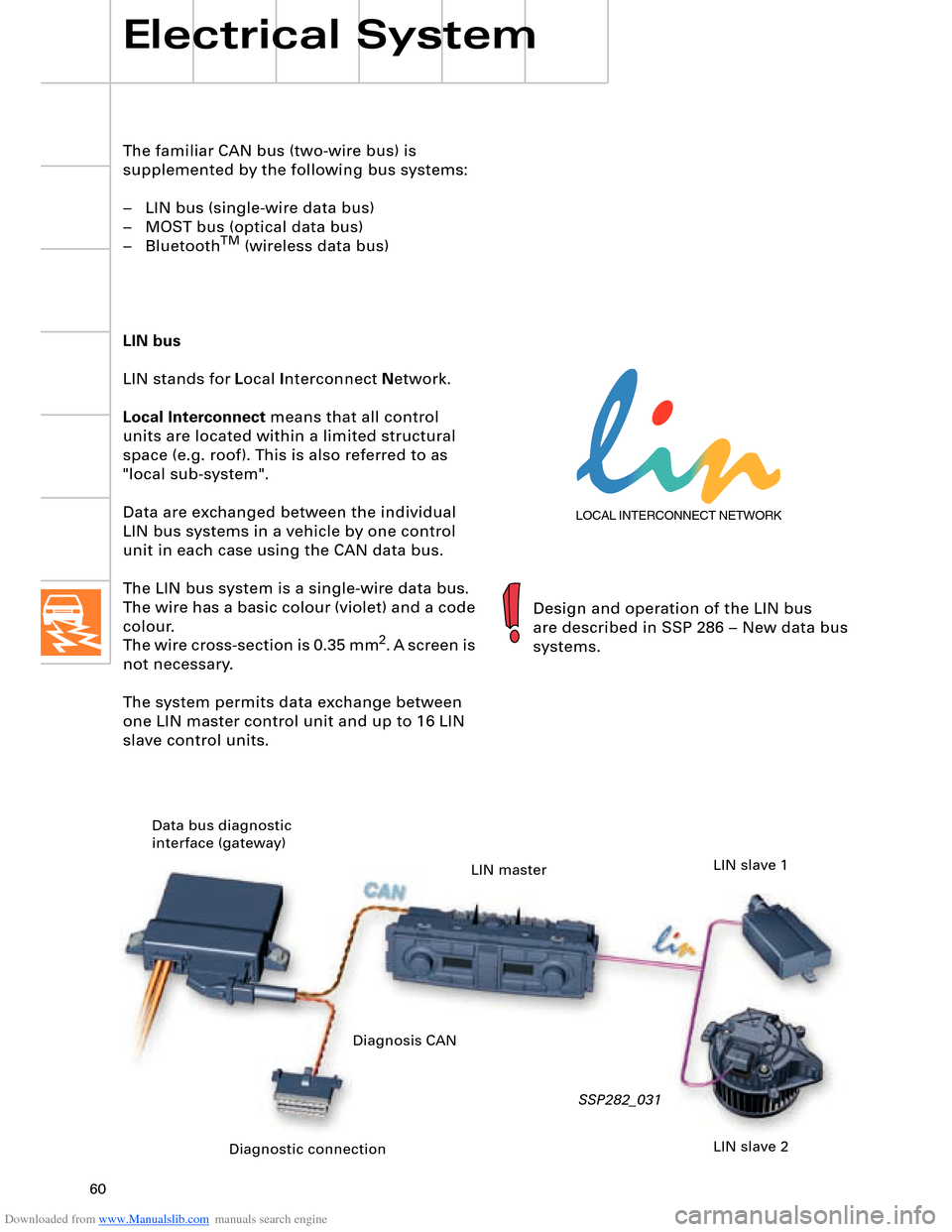
The familiar CAN bus (two-wire bus) is
supplemented by the following bus systems:
– LIN bus (single-wire data bus)
– MOST bus (optical data bus)
– Bluetooth
TM (wireless data bus)
LIN bus
LIN stands for Local Interconnect Network.
Local Interconnect means that all control
units are located within a limited structural
space (e.g. roof). This is also referred to as
"local sub-system".
Data are exchanged between the individual
LIN bus systems in a vehicle by one control
unit in each case using the CAN data bus.
The LIN bus system is a single-wire data bus.
The wire has a basic colour (violet) and a code
colour.
The wire cross-section is 0.35 mm
2. A screen is
not necessary.
The system permits data exchange between
one LIN master control unit and up to 16 LIN
slave control units.
SSP282_031
Design and operation of the LIN bus
are described in SSP 286 – New data bus
systems.
Diagnostic connection Data bus diagnostic
interface (gateway)
LIN master
LIN slave 2 LIN slave 1
Diagnosis CAN