Ignition lock AUDI A8 2003 D3 / 2.G Technical Features Manual
[x] Cancel search | Manufacturer: AUDI, Model Year: 2003, Model line: A8, Model: AUDI A8 2003 D3 / 2.GPages: 96, PDF Size: 5.51 MB
Page 43 of 96

Downloaded from www.Manualslib.com manuals search engine 43
D1
30
15
J329J53J695J694
75xE415
N376
6x
J623
J518
50R
50R
3
12
12
E408
STOP START
58s
210 210
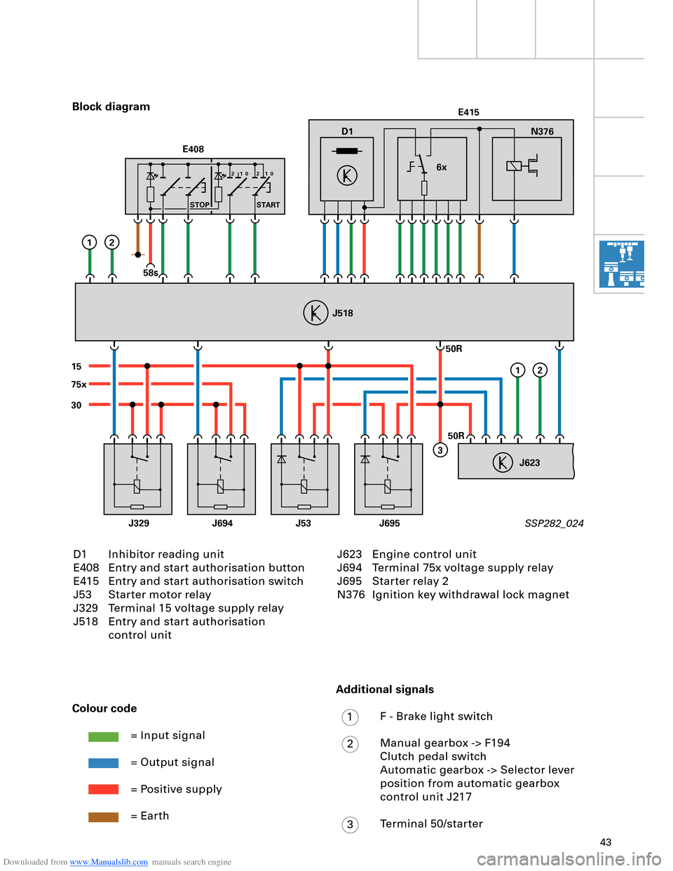
D1 Inhibitor reading unit
E408 Entry and start authorisation button
E415 Entry and start authorisation switch
J53 Starter motor relay
J329 Terminal 15 voltage supply relay
J518 Entry and start authorisation
control unit Block diagram
SSP282_024
Colour code
= Input signal
= Output signal
= Positive supply
= Earth
J623 Engine control unit
J694 Terminal 75x voltage supply relay
J695 Starter relay 2
N376 Ignition key withdrawal lock magnet
Additional signals
F - Brake light switch
Manual gearbox -> F194
Clutch pedal switch
Automatic gearbox -> Selector lever
position from automatic gearbox
control unit J217
Terminal 50/starter
1
2
3
Page 44 of 96

Downloaded from www.Manualslib.com manuals search engine 44
Engine, Mechanics
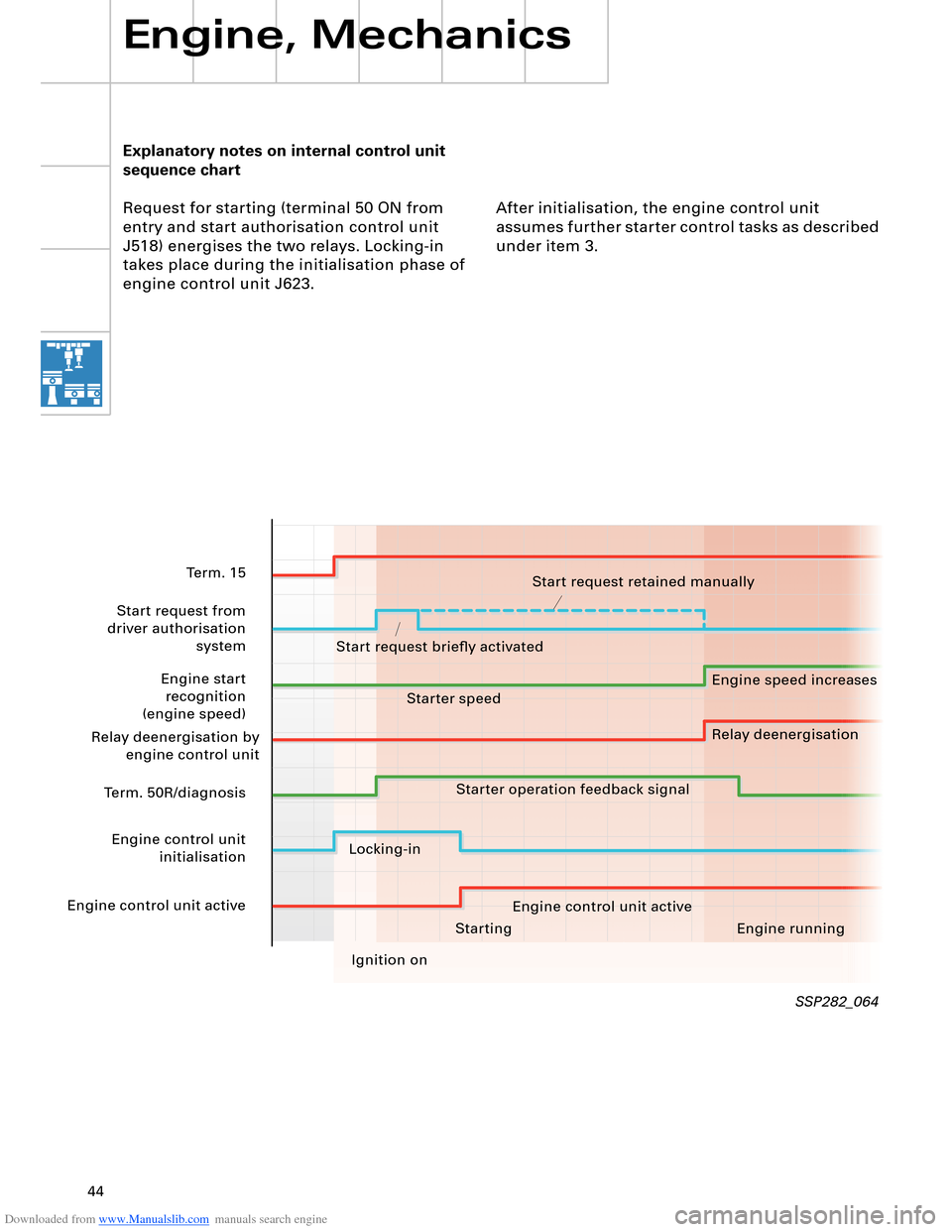
Explanatory notes on internal control unit
sequence chart
Request for starting (terminal 50 ON from
entry and start authorisation control unit
J518) energises the two relays. Locking-in
takes place during the initialisation phase of
engine control unit J623.After initialisation, the engine control unit
assumes further starter control tasks as described
under item 3.
SSP282_064
Starting Engine running
Ignition on
Term. 15
Start request from
driver authorisation system
Engine start recognition
(engine speed)
Relay deenergisation by engine control unit
Term. 50R/diagnosis
Engine control unit initialisation
Engine control unit active Start request retained manually
Start request briefly activated Engine speed increases
Relay deenergisation
Starter speed
Starter operation feedback signal
Locking-in Engine control unit active
Page 48 of 96

Downloaded from www.Manualslib.com manuals search engine 48
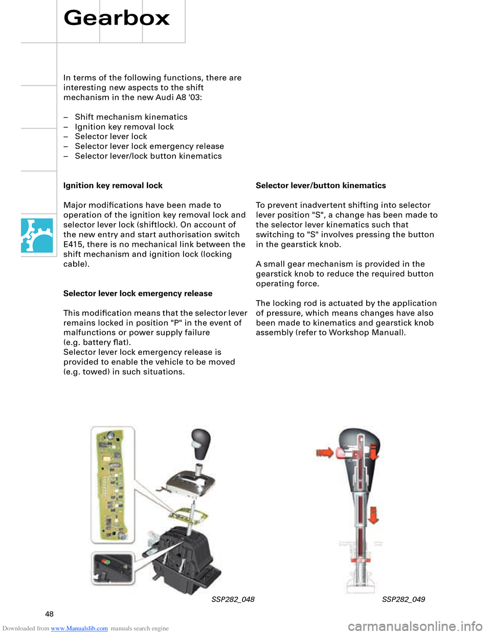
Selector lever/button kinematics
To prevent inadvertent shifting into selector
lever position "S", a change has been made to
the selector lever kinematics such that
switching to "S" involves pressing the button
in the gearstick knob.
A small gear mechanism is provided in the
gearstick knob to reduce the required button
operating force.
The locking rod is actuated by the application
of pressure, which means changes have also
been made to kinematics and gearstick knob
assembly (refer to Workshop Manual).
In terms of the following functions, there are
interesting new aspects to the shift
mechanism in the new Audi A8 '03:
– Shift mechanism kinematics
– Ignition key removal lock
– Selector lever lock
– Selector lever lock emergency release
– Selector lever/lock button kinematics
Ignition key removal lock
Major modifications have been made to
operation of the ignition key removal lock and
selector lever lock (shiftlock). On account of
the new entry and start authorisation switch
E415, there is no mechanical link between the
shift mechanism and ignition lock (locking
cable).
Selector lever lock emergency release
This modification means that the selector lever
remains locked in position "P" in the event of
malfunctions or power supply failure
(e.g. battery flat).
Selector lever lock emergency release is
provided to enable the vehicle to be moved
(e.g. towed) in such situations.
Gearbox
SSP282_048 SSP282_049
Page 64 of 96

Downloaded from www.Manualslib.com manuals search engine 64
Electrical System
Convenience and security
electronics
"Advanced Key" entry and start
authorisation system
"Advanced Key" can be taken to mean an
"advanced locking and security system".
It takes the form of a non-contacting key
recognition system. With the "Advanced Key"
package, the "Vehicle unlocking" and "Vehicle
locking" functions by way of a mechanical or
remote control key are supplemented by the non-
contacting functions "Vehicle unlocking" and
"Vehicle locking".
Functions
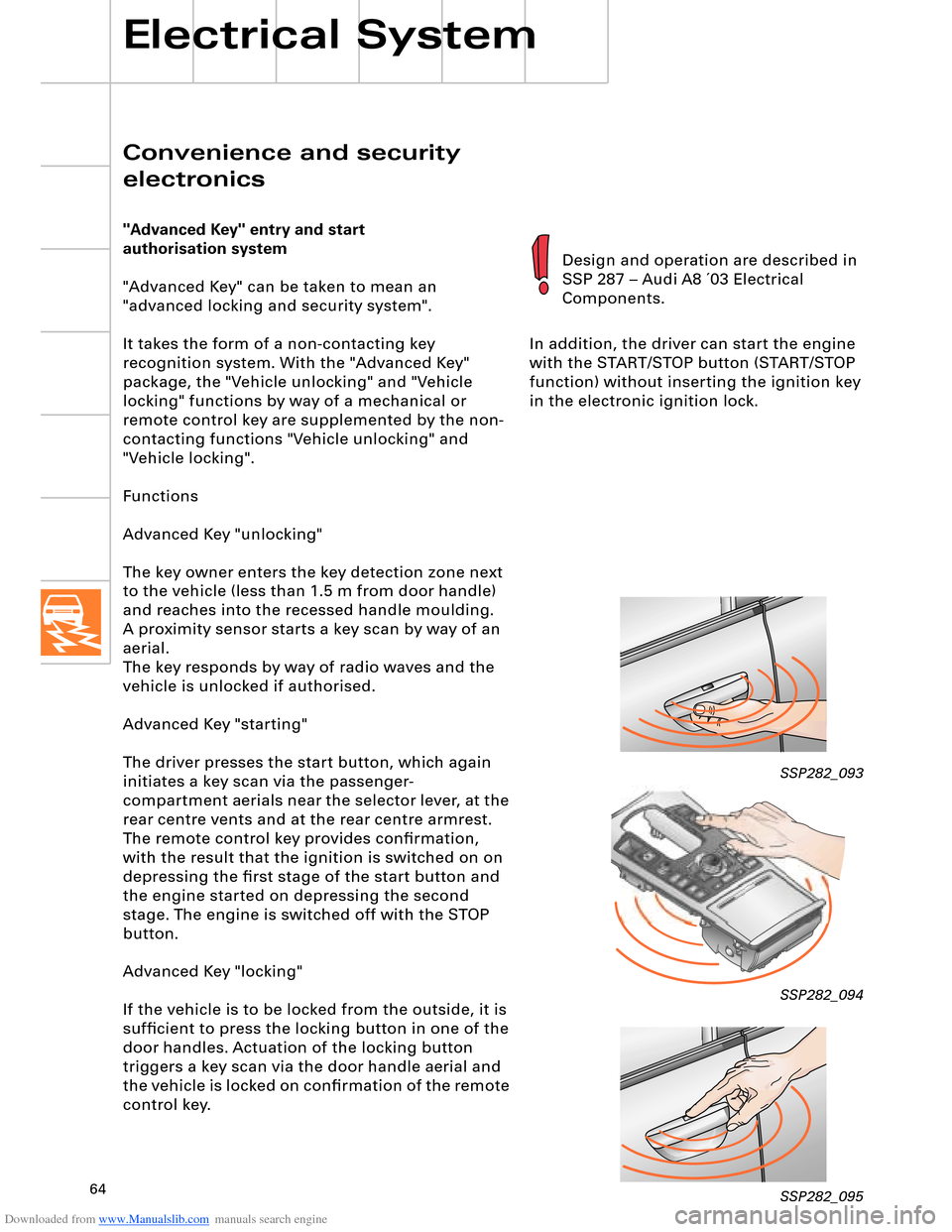
Advanced Key "unlocking"
The key owner enters the key detection zone next
to the vehicle (less than 1.5 m from door handle)
and reaches into the recessed handle moulding.
aerial.
The key responds by way of radio waves and the
vehicle is unlocked if authorised.
Advanced Key "starting"
The driver presses the start button, which again
initiates a key scan via the passenger-
compartment aerials near the selector lever, at the
rear centre vents and at the rear centre armrest.
The remote control key provides confirmation,
with the result that the ignition is switched on on
depressing the first stage of the start button and
the engine started on depressing the second
stage. The engine is switched off with the STOP
button.
Advanced Key "locking"
If the vehicle is to be locked from the outside, it is
sufficient to press the locking button in one of the
door handles. Actuation of the locking button
triggers a key scan via the door handle aerial and
the vehicle is locked on confirmation of the remote
control key.In addition, the driver can start the engine
with the START/STOP button (START/STOP
function) without inserting the ignition key
in the electronic ignition lock.
SSP282_093
SSP282_094
SSP282_095
Design and operation are described in
SSP 287 – Audi A8 ´03 Electrical
Components.
A proximity sensor starts a key scan by way of an
Page 73 of 96

Downloaded from www.Manualslib.com manuals search engine 7374
A distinction is made between two air
conditioner unit versions
– 2-zone front and rear climate
control
– 4-zone front and rear climate
control
and three types of control and
display unit
– Air conditioner control panel with
no seat heating/ventilation
– Air conditioner control panel with
seat heating
– Air conditioner control panel with
seat heating and seat ventilation
(identified by part number index).
SSP282_099
Self-diagnosis
Fault diagnosis and measured value blocks
for air conditioner and seat heating system
can be read out by way of address words 08
"Air conditioner/heater electronics" and 28
"Rear climate control". The functions of and
exact procedure for self-diagnosis and
assisted fault-finding with VAS 5051 can be
found in the Heating/Air Conditioner
Workshop Manual for the relevant vehicle
model.
Operating principle
When the ignition is switched on, the
Climatronic control unit J255 starts up with
the same temperature, air distribution and
fresh-air blower speed settings etc. as were
applicable the last time the ignition was
switched off by way of the appropriate key or
using fingerprint recognition.
If fingerprint recognition has been
implemented, this has priority over key
recognition (refer also to SSP 287 – Audi A8 ´03
Electrical Components).
Personalised settings
The following settings can be made for each
climate control zone (front left, right and,
optionally, with 4-zone climate control rear left
and right):
– Left/right temperature
– Air flow
– Left/right air distribution
– Left/right seat heating
– Left/right seat ventilation
– Operating modes (AUTO for driver and front
passenger, temperature-adjustable centre
vents, automatically controlled
recirculated-air mode, ECON)
The heated windscreen can be activated by
way of the air conditioner defrost button or
the air conditioner control unit automatically
switches on the electric heated windscreen if
the appropriate conditions are satisfied
(windscreen defrost or automatic mode on
cold starting).
The Climatronic J255 and heated windscreen
J505 control units communicate by way of the
LIN bus. The Climatronic control unit transmits
the specified windscreen heating power to the
heated windscreen control unit on the LIN bus.
Heating/Air Conditioner
Key recognition takes place in the case of
remote control (radio or key transponder),
with the driver identification control unit
providing the Climatronic control unit J255
with the appropriate information by way of
the CAN bus.
The electrically heated windscreen is only
supplied with the amount of power which can
currently be drawn from the electrical system
without draining the battery. This is
monitored by the energy management
control unit J644.
As is the case with the Audi A4, the
windscreen is heated by applying voltage to a
metallic foil fitted in the glass (refer to
SSP 213).
As in the Audi A4, the air conditioner
compressor is regulated as a function of load
and controlled externally by way of the
compressor regulating valve (refer to
SSP 240). The Climatronic control unit J255 is
connected to the convenience CAN, via
which diagnosis is also performed.
A manual air conditioning system is not
available.