tow BMW 2 SERIES CONVERTIBLE 2016 F23 Owner's Guide
[x] Cancel search | Manufacturer: BMW, Model Year: 2016, Model line: 2 SERIES CONVERTIBLE, Model: BMW 2 SERIES CONVERTIBLE 2016 F23Pages: 234, PDF Size: 5.93 MB
Page 170 of 234
prox. 50 km/h to 100 mph, approx. 160 km/h, if
the following conditions are met:▷Accelerator pedal and brake pedal are not
operated.▷The selector lever is in selector lever posi‐
tion D.▷Engine and transmission are at operating
temperature.
The driving status Coast can be influenced
with the shift paddles.
Display Display in the instrument cluster
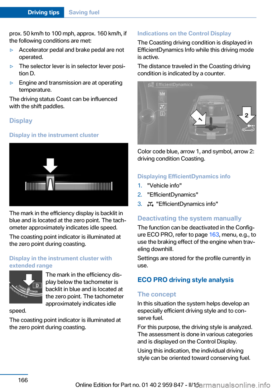
The mark in the efficiency display is backlit in
blue and is located at the zero point. The tach‐
ometer approximately indicates idle speed.
The coasting point indicator is illuminated at
the zero point during coasting.
Display in the instrument cluster with
extended range
The mark in the efficiency dis‐
play below the tachometer is
backlit in blue and is located at
the zero point. The tachometer
approximately indicates idle
speed.
The coasting point indicator is illuminated at
the zero point during coasting.
Indications on the Control Display
The Coasting driving condition is displayed in
EfficientDynamics Info while this driving mode
is active.
The distance traveled in the Coasting driving
condition is indicated by a counter.
Color code blue, arrow 1, and symbol, arrow 2:
driving condition Coasting.
Displaying EfficientDynamics info
1."Vehicle info"2."EfficientDynamics"3. "EfficientDynamics info"
Deactivating the system manually The function can be deactivated in the Config‐
ure ECO PRO, refer to page 163, menu, e.g., to
use the braking effect of the engine when trav‐
eling downhill.
Settings are stored for the profile currently in
use.
ECO PRO driving style analysis
The concept
In this situation the system helps develop an
especially efficient driving style and to con‐
serve fuel.
For this purpose, the driving style is analyzed.
The assessment is done in various categories
and is displayed on the Control Display.
Using this indication, the individual driving
style can be oriented toward conserving fuel.
Seite 166Driving tipsSaving fuel166
Online Edition for Part no. 01 40 2 959 847 - II/15
Page 183 of 234
0115: tire age
Tires with DOT codes meet the guidelines of
the U.S. Department of Transportation.
Tire age DOT … 0115: the tire was manufactured in the
1st week of 2015.
Recommendation
Regardless of wear and tear, replace tires at
least every 6 years.
Uniform Tire Quality Grading Quality grades can be found where applicable
on the tire sidewall between tread shoulder
and maximum section width.
For example: Treadwear 200; Traction AA;
Temperature A
DOT Quality Grades
Treadwear
Traction AA A B C
Temperature A B C
All passenger car tires must conform to Fed‐
eral Safety Requirements in addition to these
grades.
TreadwearThe treadwear grade is a comparative rating
based on the wear rate of the tire when tested
under controlled conditions on a specified gov‐
ernment test course. For example, a tire graded 150 would wear one and one-half, 1 g,
times as well on the government course as a
tire graded 100. The relative performance of
tires depends upon the actual conditions of
their use, however, and may depart signifi‐
cantly from the norm due to variations in driv‐
ing habits, service practices and differences in
road characteristics and climate.Traction
The traction grades, from highest to lowest,
are AA, A, B, and C.
Those grades represent the tire's ability to
stop on wet pavement as measured under
controlled conditions on specified government
test surfaces of asphalt and concrete. A tire
marked C may have poor traction performance.
The traction grade assigned to this tire is
based on straight-ahead braking traction tests,
and does not include acceleration, cornering,
hydroplaning, or peak traction characteristics.
Temperature
The temperature grades are A, the highest, B,
and C, representing the tire's resistance to the
generation of heat and its ability to dissipate
heat when tested under controlled conditions
on a specified indoor laboratory test wheel.
Sustained high temperature can cause the ma‐
terial of the tire to degenerate and reduce tire
life, and excessive temperature can lead to
sudden tire failure. The grade C corresponds
to a level of performance which all passenger
car tires must meet under the Federal Motor
Vehicle Safety Standard No. 109. Grades Band
A represent higher levels of performance on
the laboratory test wheel than the minimum re‐
quired by law.
Temperature grade for this tire
The temperature grade for this tire is es‐
tablished for a tire that is properly inflated and
not overloaded. Excessive speed, underinfla‐
tion, or excessive loading, either separately or
in combination, can cause heat buildup and
possible tire failure.
If necessary, have the vehicle towed.◀
RSC – Run-flat tires
Run-flat tires, refer to page 182, are labeled
with a circular symbol containing the letters
RSC marked on the sidewall.Seite 179Wheels and tiresMobility179
Online Edition for Part no. 01 40 2 959 847 - II/15
Page 184 of 234
M+S
Winter and all-season tires with better cold
weather performance than summer tires.
Tire tread Summer tires
Do not drive with a tire tread depth of less than
0.12 in/3 mm.
There is an increased danger of hydroplaning if
the tire tread depth is less than 0.12 in/3 mm.
Winter tires
Do not drive with a tire tread depth of less than
0.16 in/4 mm.
Below a tread depth of 0.16 in/4 mm, tires are
less suitable for winter operation.
Minimum tread depth
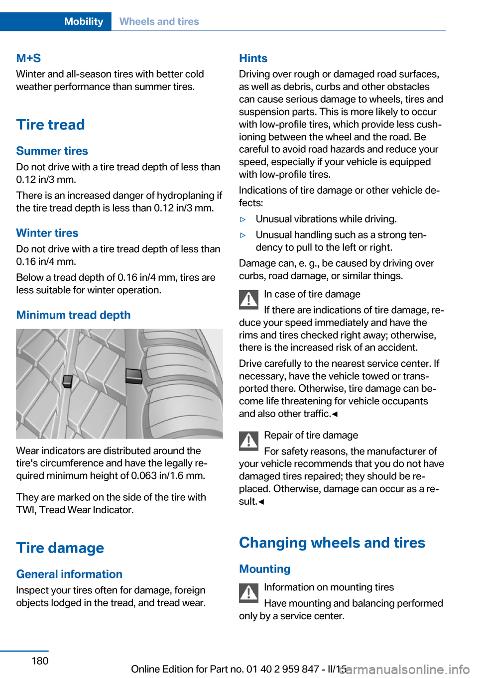
Wear indicators are distributed around the
tire's circumference and have the legally re‐
quired minimum height of 0.063 in/1.6 mm.
They are marked on the side of the tire with
TWI, Tread Wear Indicator.
Tire damage
General information
Inspect your tires often for damage, foreign
objects lodged in the tread, and tread wear.
Hints
Driving over rough or damaged road surfaces,
as well as debris, curbs and other obstacles can cause serious damage to wheels, tires and
suspension parts. This is more likely to occur
with low-profile tires, which provide less cush‐
ioning between the wheel and the road. Be
careful to avoid road hazards and reduce your
speed, especially if your vehicle is equipped
with low-profile tires.
Indications of tire damage or other vehicle de‐
fects:▷Unusual vibrations while driving.▷Unusual handling such as a strong ten‐
dency to pull to the left or right.
Damage can, e. g., be caused by driving over
curbs, road damage, or similar things.
In case of tire damage
If there are indications of tire damage, re‐
duce your speed immediately and have the
rims and tires checked right away; otherwise,
there is the increased risk of an accident.
Drive carefully to the nearest service center. If
necessary, have the vehicle towed or trans‐
ported there. Otherwise, tire damage can be‐
come life threatening for vehicle occupants
and also other traffic.◀
Repair of tire damage
For safety reasons, the manufacturer of
your vehicle recommends that you do not have
damaged tires repaired; they should be re‐
placed. Otherwise, damage can occur as a re‐
sult.◀
Changing wheels and tires
Mounting Information on mounting tires
Have mounting and balancing performed
only by a service center.
Seite 180MobilityWheels and tires180
Online Edition for Part no. 01 40 2 959 847 - II/15
Page 187 of 234
exhaust gases contain carbon monoxide, an
odorless and colorless but highly toxic gas.◀
Storage The Mobility System is located under the
cargo floor panel.
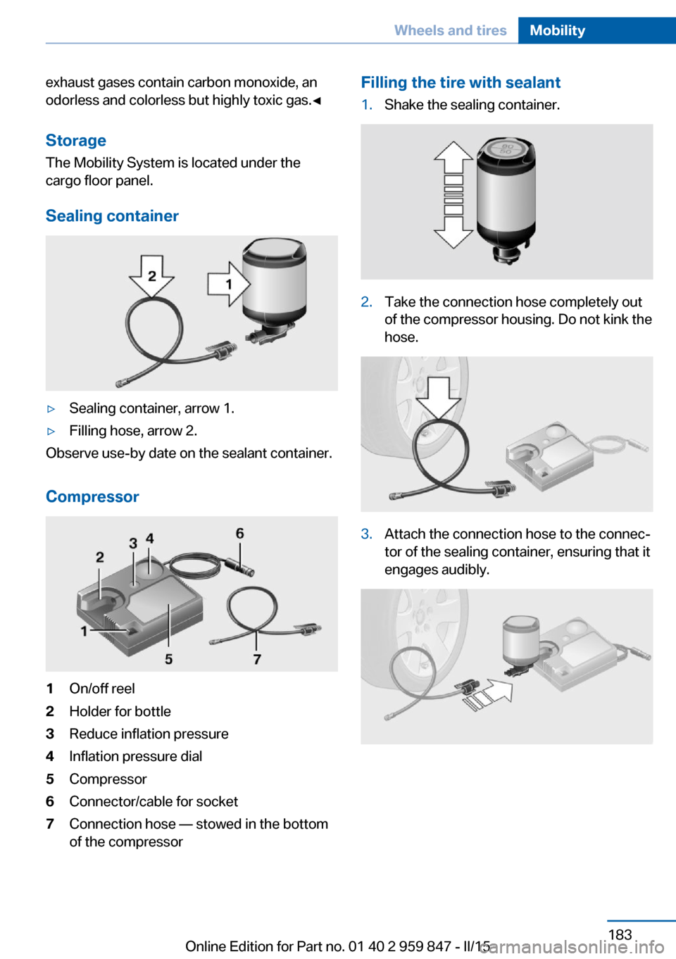
Sealing container▷Sealing container, arrow 1.▷Filling hose, arrow 2.
Observe use-by date on the sealant container.
Compressor
1On/off reel2Holder for bottle3Reduce inflation pressure4Inflation pressure dial5Compressor6Connector/cable for socket7Connection hose — stowed in the bottom
of the compressorFilling the tire with sealant1.Shake the sealing container.2.Take the connection hose completely out
of the compressor housing. Do not kink the
hose.3.Attach the connection hose to the connec‐
tor of the sealing container, ensuring that it
engages audibly.Seite 183Wheels and tiresMobility183
Online Edition for Part no. 01 40 2 959 847 - II/15
Page 188 of 234
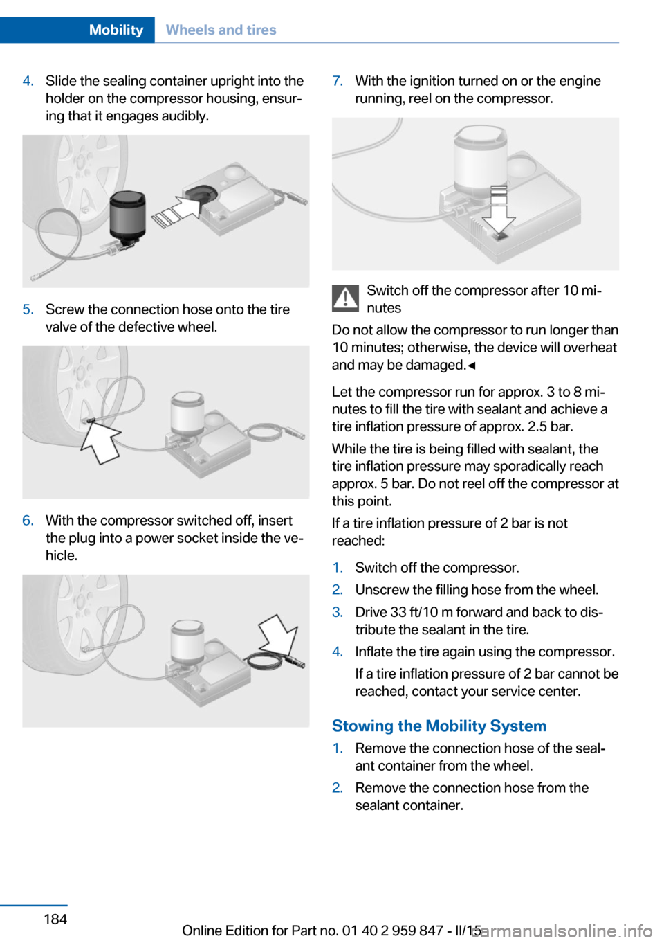
4.Slide the sealing container upright into the
holder on the compressor housing, ensur‐
ing that it engages audibly.5.Screw the connection hose onto the tire
valve of the defective wheel.6.With the compressor switched off, insert
the plug into a power socket inside the ve‐
hicle.7.With the ignition turned on or the engine
running, reel on the compressor.
Switch off the compressor after 10 mi‐
nutes
Do not allow the compressor to run longer than
10 minutes; otherwise, the device will overheat
and may be damaged.◀
Let the compressor run for approx. 3 to 8 mi‐
nutes to fill the tire with sealant and achieve a
tire inflation pressure of approx. 2.5 bar.
While the tire is being filled with sealant, the
tire inflation pressure may sporadically reach
approx. 5 bar. Do not reel off the compressor at
this point.
If a tire inflation pressure of 2 bar is not
reached:
1.Switch off the compressor.2.Unscrew the filling hose from the wheel.3.Drive 33 ft/10 m forward and back to dis‐
tribute the sealant in the tire.4.Inflate the tire again using the compressor.
If a tire inflation pressure of 2 bar cannot be
reached, contact your service center.
Stowing the Mobility System
1.Remove the connection hose of the seal‐
ant container from the wheel.2.Remove the connection hose from the
sealant container.Seite 184MobilityWheels and tires184
Online Edition for Part no. 01 40 2 959 847 - II/15
Page 189 of 234
3.Wrap the empty sealant container and con‐
nection hose in suitable material to avoid
dirtying the cargo area.4.Stow the Mobility System back in the vehi‐
cle.
Distributing the sealant
Immediately drive approx. 5 miles/10 km to en‐
sure that the sealant is evenly distributed in the
tire.
Do not exceed a speed of 50 mph/80 km/h.
If possible, do not drive at speeds less than
12 mph/20 km/h.
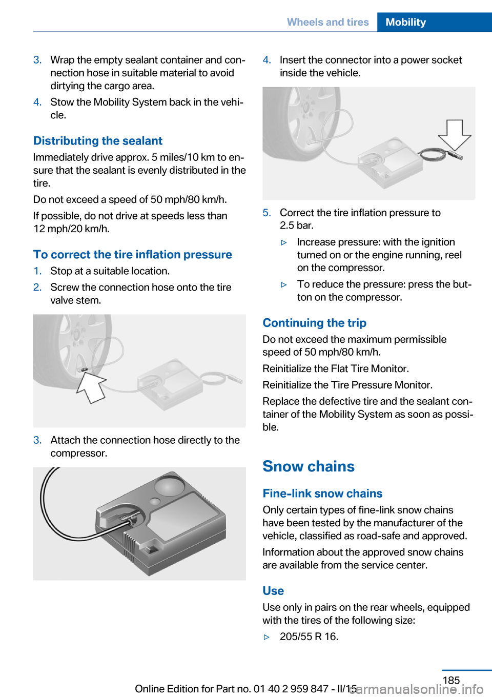
To correct the tire inflation pressure
1.Stop at a suitable location.2.Screw the connection hose onto the tire
valve stem.3.Attach the connection hose directly to the
compressor.4.Insert the connector into a power socket
inside the vehicle.5.Correct the tire inflation pressure to
2.5 bar.▷Increase pressure: with the ignition
turned on or the engine running, reel
on the compressor.▷To reduce the pressure: press the but‐
ton on the compressor.
Continuing the trip
Do not exceed the maximum permissible
speed of 50 mph/80 km/h.
Reinitialize the Flat Tire Monitor.
Reinitialize the Tire Pressure Monitor.
Replace the defective tire and the sealant con‐
tainer of the Mobility System as soon as possi‐
ble.
Snow chains Fine-link snow chains
Only certain types of fine-link snow chains
have been tested by the manufacturer of the
vehicle, classified as road-safe and approved.
Information about the approved snow chains
are available from the service center.
Use
Use only in pairs on the rear wheels, equipped
with the tires of the following size:
▷205/55 R 16.Seite 185Wheels and tiresMobility185
Online Edition for Part no. 01 40 2 959 847 - II/15
Page 196 of 234
CoolantVehicle features and optionsThis chapter describes all standard, country-
specific and optional features offered with the
series. It also describes features that are not
necessarily available in your car, e. g., due to
the selected options or country versions. This
also applies to safety-related functions and
systems. The respectively applicable country
provisions must be observed when using the
respective features and systems.
Hints Danger of burns from hot engine
Do not open the cooling system while
the engine is hot; otherwise, esliding coolant
may cause burns.◀
Suitable additives
Only use suitable additives; otherwise,
engine damage may occur. The additives are
harmful to your health.◀
Coolant consists of water and additives.
Not all commercially available additives are
suitable for the vehicle. Information about the
suitable additives are available from the service
center.
Coolant level
General information
Depending on the engine installation, the cool‐
ant reservoir is located on the right side or the
left side of the engine compartment.
Checking1.Let the engine cool.2.The coolant level is correct if it lies be‐
tween the minimum and maximum marks.The marks are on the side of the coolant
reservoir.SymbolMeaningMaximumMinimum
Adding
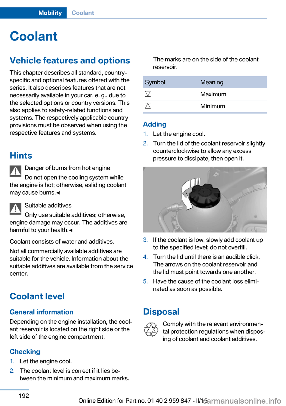
1.Let the engine cool.2.Turn the lid of the coolant reservoir slightly
counterclockwise to allow any excess
pressure to dissipate, then open it.3.If the coolant is low, slowly add coolant up
to the specified level; do not overfill.4.Turn the lid until there is an audible click.
The arrows on the coolant reservoir and
the lid must point towards one another.5.Have the cause of the coolant loss elimi‐
nated as soon as possible.
Disposal
Comply with the relevant environmen‐
tal protection regulations when dispos‐
ing of coolant and coolant additives.
Seite 192MobilityCoolant192
Online Edition for Part no. 01 40 2 959 847 - II/15
Page 211 of 234
Tow-starting and towingNote Tow-starting and towing
For tow-starting or towing, switch off the
Intelligent Safety systems; otherwise malfunc‐
tions of the individual braking systems might
lead to accidents.◀
Manual transmission Gearshift lever in neutral position.
Towing Follow the towing instructions
Follow all towing instructions; otherwise,
vehicle damage or accidents may occur.◀▷Make sure that the ignition is switched on;
otherwise, the low beams, tail lights, turn
signals, and wipers may be unavailable.▷Do not tow the vehicle with the rear axle
tilted, as the front wheels could turn.▷When the engine is stopped, there is no
power assist. Consequently, more force
needs to be applied when braking and
steering.▷Larger steering wheel movements are re‐
quired.▷The towing vehicle must not be lighter
than the vehicle being towed; otherwise,
it will not be possible to control the vehi‐
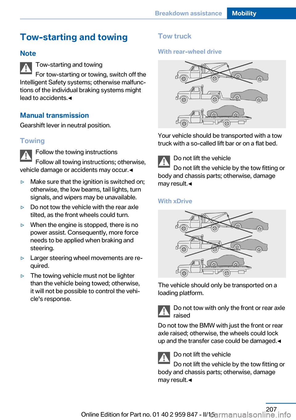
cle's response.Tow truck
With rear-wheel drive
Your vehicle should be transported with a tow
truck with a so-called lift bar or on a flat bed.
Do not lift the vehicle
Do not lift the vehicle by the tow fitting or
body and chassis parts; otherwise, damage
may result.◀
With xDrive
The vehicle should only be transported on a
loading platform.
Do not tow with only the front or rear axle
raised
Do not tow the BMW with just the front or rear
axle raised; otherwise, the wheels could lock
up and the transfer case could be damaged.◀
Do not lift the vehicle
Do not lift the vehicle by the tow fitting or
body and chassis parts; otherwise, damage
may result.◀
Seite 207Breakdown assistanceMobility207
Online Edition for Part no. 01 40 2 959 847 - II/15
Page 212 of 234
Steptronic transmission: transporting
your vehicle
Note Your vehicle is not permitted to be towed.
Therefore, contact a service center in the
event of a breakdown.
Do not have the vehicle towed
Have your vehicle transported on a load‐
ing platform only; otherwise, damage may oc‐
cur.◀
Tow truck
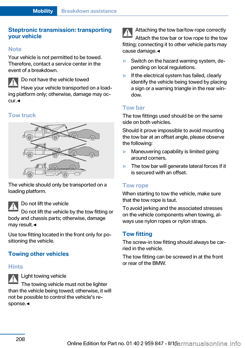
The vehicle should only be transported on a
loading platform.
Do not lift the vehicle
Do not lift the vehicle by the tow fitting or
body and chassis parts; otherwise, damage
may result.◀
Use tow fitting located in the front only for po‐
sitioning the vehicle.
Towing other vehicles
Hints Light towing vehicle
The towing vehicle must not be lighter
than the vehicle being towed; otherwise, it will
not be possible to control the vehicle's re‐
sponse.◀
Attaching the tow bar/tow rope correctly
Attach the tow bar or tow rope to the tow
fitting; connecting it to other vehicle parts may
cause damage.◀▷Switch on the hazard warning system, de‐
pending on local regulations.▷If the electrical system has failed, clearly
identify the vehicle being towed by placing
a sign or a warning triangle in the rear win‐
dow.
Tow bar
The tow fittings used should be on the same
side on both vehicles.
Should it prove impossible to avoid mounting
the tow bar at an offset angle, please observe
the following:
▷Maneuvering capability is limited going
around corners.▷The tow bar will generate lateral forces if it
is secured with an offset.
Tow rope
When starting to tow the vehicle, make sure
that the tow rope is taut.
To avoid jerking and the associated stresses
on the vehicle components when towing, al‐
ways use nylon ropes or nylon straps.
Tow fitting
The screw-in tow fitting should always be car‐
ried in the vehicle.
The tow fitting can be screwed in at the front
or rear of the BMW.
Seite 208MobilityBreakdown assistance208
Online Edition for Part no. 01 40 2 959 847 - II/15
Page 213 of 234
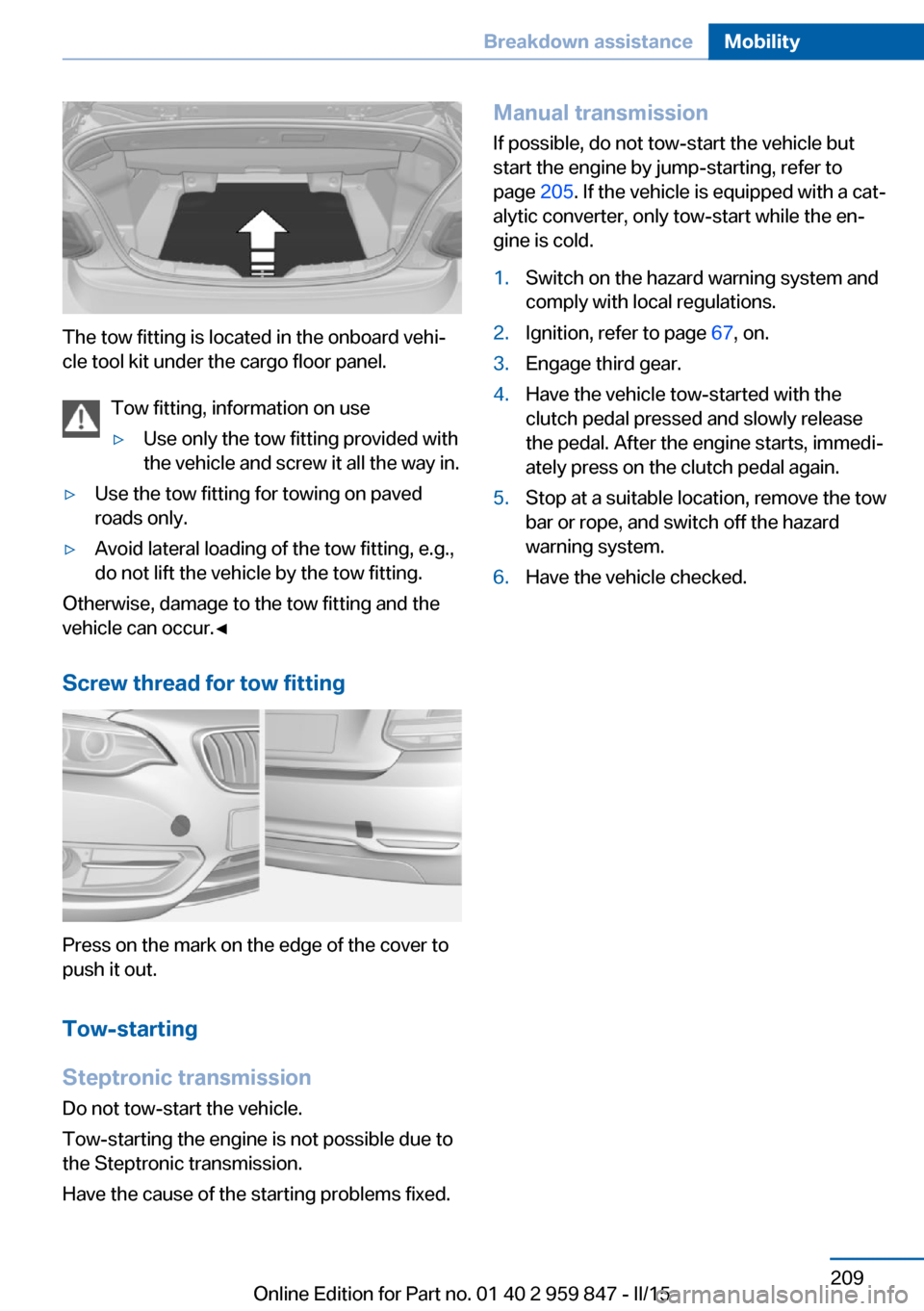
The tow fitting is located in the onboard vehi‐
cle tool kit under the cargo floor panel.
Tow fitting, information on use
▷Use only the tow fitting provided with
the vehicle and screw it all the way in.▷Use the tow fitting for towing on paved
roads only.▷Avoid lateral loading of the tow fitting, e.g.,
do not lift the vehicle by the tow fitting.
Otherwise, damage to the tow fitting and the
vehicle can occur.◀
Screw thread for tow fitting
Press on the mark on the edge of the cover to
push it out.
Tow-starting
Steptronic transmission
Do not tow-start the vehicle.
Tow-starting the engine is not possible due to
the Steptronic transmission.
Have the cause of the starting problems fixed.
Manual transmission If possible, do not tow-start the vehicle but
start the engine by jump-starting, refer to
page 205. If the vehicle is equipped with a cat‐
alytic converter, only tow-start while the en‐
gine is cold.1.Switch on the hazard warning system and
comply with local regulations.2.Ignition, refer to page 67, on.3.Engage third gear.4.Have the vehicle tow-started with the
clutch pedal pressed and slowly release
the pedal. After the engine starts, immedi‐
ately press on the clutch pedal again.5.Stop at a suitable location, remove the tow
bar or rope, and switch off the hazard
warning system.6.Have the vehicle checked.Seite 209Breakdown assistanceMobility209
Online Edition for Part no. 01 40 2 959 847 - II/15