clock BMW 3 SERIES 1983 E30 User Guide
[x] Cancel search | Manufacturer: BMW, Model Year: 1983, Model line: 3 SERIES, Model: BMW 3 SERIES 1983 E30Pages: 228, PDF Size: 7.04 MB
Page 83 of 228
3-Series models
14Remove the radiator grille assembly (see
Chapter 11).
15Unbolt and remove the fan bracket and
shroud assembly from the radiator (see
Section 5).
16Remove the radiator (see Section 4).
17Unbolt the air conditioning condenser
mounting bolts, where applicable. Do not
remove the condenser or disconnect any
refrigerant lines from the condenser.
18Carefully pull the condenser back towards
the engine, slightly, to gain access to lift the
auxiliary fan.
19Disconnect the fan motor electrical
connection and remove the auxiliary fan.
20Refitting is the reverse of removal.
5-Series models
21Remove the screws and trim panel in front
of the radiator.
22Unbolt the fan assembly from the
condenser mounting points.
23Disconnect the fan electrical connector.
24Remove the fan and housing from the car,
being careful not to damage the air
conditioning condenser (when applicable)
while removing the fan.
25Refitting is the reverse of removal.
Mechanical fan with viscous clutch
26Disconnect the battery negative cable.
Remove the fan shroud mounting screws or
plastic fasteners, and detach the shroud (see
Section 4).
27 Use a 32 mm open-ended spanner to
remove the fan/clutch assembly. Place the
spanner on the large nut ahead of the pulley
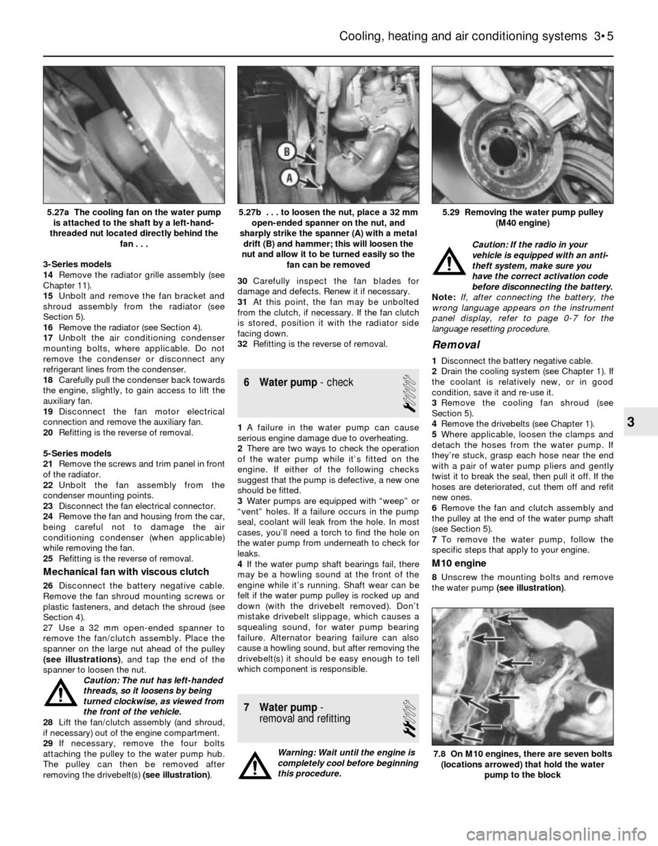
(see illustrations), and tap the end of the
spanner to loosen the nut.
Caution: The nut has left-handed
threads, so it loosens by being
turned clockwise, as viewed from
the front of the vehicle.
28Lift the fan/clutch assembly (and shroud,
if necessary) out of the engine compartment.
29If necessary, remove the four bolts
attaching the pulley to the water pump hub.
The pulley can then be removed after
removing the drivebelt(s) (see illustration).30Carefully inspect the fan blades for
damage and defects. Renew it if necessary.
31At this point, the fan may be unbolted
from the clutch, if necessary. If the fan clutch
is stored, position it with the radiator side
facing down.
32Refitting is the reverse of removal.
6 Water pump- check
1
1A failure in the water pump can cause
serious engine damage due to overheating.
2There are two ways to check the operation
of the water pump while it’s fitted on the
engine. If either of the following checks
suggest that the pump is defective, a new one
should be fitted.
3Water pumps are equipped with “weep” or
“vent” holes. If a failure occurs in the pump
seal, coolant will leak from the hole. In most
cases, you’ll need a torch to find the hole on
the water pump from underneath to check for
leaks.
4If the water pump shaft bearings fail, there
may be a howling sound at the front of the
engine while it’s running. Shaft wear can be
felt if the water pump pulley is rocked up and
down (with the drivebelt removed). Don’t
mistake drivebelt slippage, which causes a
squealing sound, for water pump bearing
failure. Alternator bearing failure can also
cause a howling sound, but after removing the
drivebelt(s) it should be easy enough to tell
which component is responsible.
7 Water pump-
removal and refitting
2
Warning: Wait until the engine is
completely cool before beginning
this procedure.Caution: If the radio in your
vehicle is equipped with an anti-
theft system, make sure you
have the correct activation code
before disconnecting the battery.
Note: If, after connecting the battery, the
wrong language appears on the instrument
panel display, refer to page 0-7 for the
language resetting procedure.
Removal
1Disconnect the battery negative cable.
2Drain the cooling system (see Chapter 1). If
the coolant is relatively new, or in good
condition, save it and re-use it.
3Remove the cooling fan shroud (see
Section 5).
4Remove the drivebelts (see Chapter 1).
5Where applicable, loosen the clamps and
detach the hoses from the water pump. If
they’re stuck, grasp each hose near the end
with a pair of water pump pliers and gently
twist it to break the seal, then pull it off. If the
hoses are deteriorated, cut them off and refit
new ones.
6Remove the fan and clutch assembly and
the pulley at the end of the water pump shaft
(see Section 5).
7To remove the water pump, follow the
specific steps that apply to your engine.
M10 engine
8Unscrew the mounting bolts and remove
the water pump (see illustration).
Cooling, heating and air conditioning systems 3•5
5.29 Removing the water pump pulley
(M40 engine)5.27b . . . to loosen the nut, place a 32 mm
open-ended spanner on the nut, and
sharply strike the spanner (A) with a metal
drift (B) and hammer; this will loosen the
nut and allow it to be turned easily so the
fan can be removed5.27a The cooling fan on the water pump
is attached to the shaft by a left-hand-
threaded nut located directly behind the
fan . . .
7.8 On M10 engines, there are seven bolts
(locations arrowed) that hold the water
pump to the block
3
Page 94 of 228
and clamps, and remove the fuel pump from
the under the vehicle.
13Refitting is the reverse of removal.
In-tank fuel pump or transfer pump
14On some models, access to the fuel pump
is gained by removing the rear seat cushion.
On other models, access is gained by
removing the carpet from the luggage
compartment.
15Remove the screws from the fuel pump
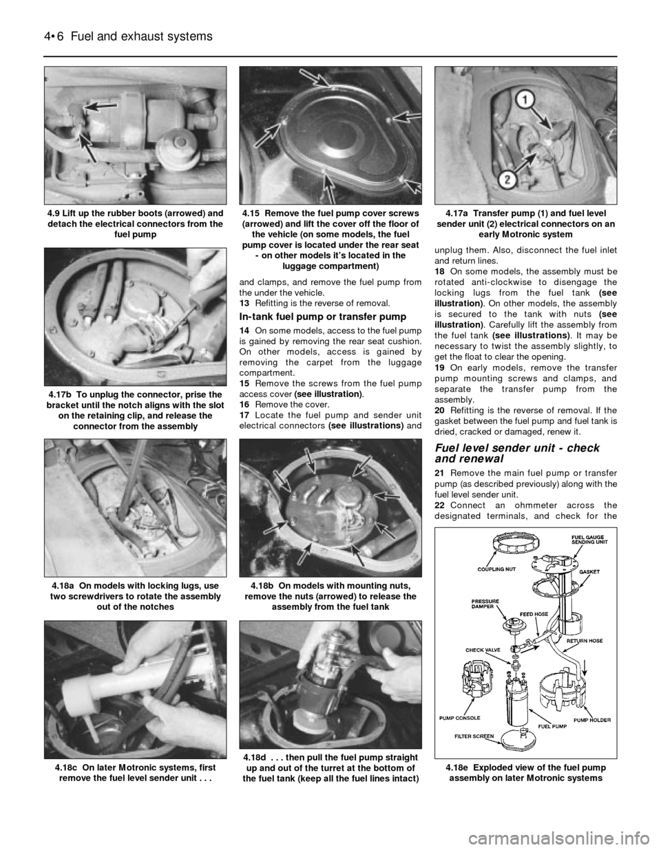
access cover (see illustration).
16Remove the cover.
17Locate the fuel pump and sender unit
electrical connectors (see illustrations)andunplug them. Also, disconnect the fuel inlet
and return lines.
18On some models, the assembly must be
rotated anti-clockwise to disengage the
locking lugs from the fuel tank (see
illustration). On other models, the assembly
is secured to the tank with nuts (see
illustration). Carefully lift the assembly from
the fuel tank (see illustrations). It may be
necessary to twist the assembly slightly, to
get the float to clear the opening.
19On early models, remove the transfer
pump mounting screws and clamps, and
separate the transfer pump from the
assembly.
20Refitting is the reverse of removal. If the
gasket between the fuel pump and fuel tank is
dried, cracked or damaged, renew it.
Fuel level sender unit - check
and renewal
21Remove the main fuel pump or transfer
pump (as described previously) along with the
fuel level sender unit.
22Connect an ohmmeter across the
designated terminals, and check for the
4•6 Fuel and exhaust systems
4.18e Exploded view of the fuel pump
assembly on later Motronic systems4.18d . . . then pull the fuel pump straight
up and out of the turret at the bottom of
the fuel tank (keep all the fuel lines intact)4.18c On later Motronic systems, first
remove the fuel level sender unit . . .
4.18b On models with mounting nuts,
remove the nuts (arrowed) to release the
assembly from the fuel tank4.18a On models with locking lugs, use
two screwdrivers to rotate the assembly
out of the notches
4.17b To unplug the connector, prise the
bracket until the notch aligns with the slot
on the retaining clip, and release the
connector from the assembly
4.17a Transfer pump (1) and fuel level
sender unit (2) electrical connectors on an
early Motronic system4.15 Remove the fuel pump cover screws
(arrowed) and lift the cover off the floor of
the vehicle (on some models, the fuel
pump cover is located under the rear seat
- on other models it’s located in the
luggage compartment)4.9 Lift up the rubber boots (arrowed) and
detach the electrical connectors from the
fuel pump
Page 108 of 228
reading should be between 400 and 500 mA.
Adjust the valve if the current reading is not as
specified. Note: The idle air stabiliser current
will fluctuate between 400 and 1100 mA if the
engine is too cold, if the coolant temperature
sensor is faulty, if there is an engine vacuum
leak, or if electrical accessories are on.
25If there is no current reading, have the idle
speed control unit (under the facia) checked
by a BMW dealer or other specialist.
26On three-wire valves, check for voltage at
the electrical connector. With the ignition on,
there should be battery voltage present at the
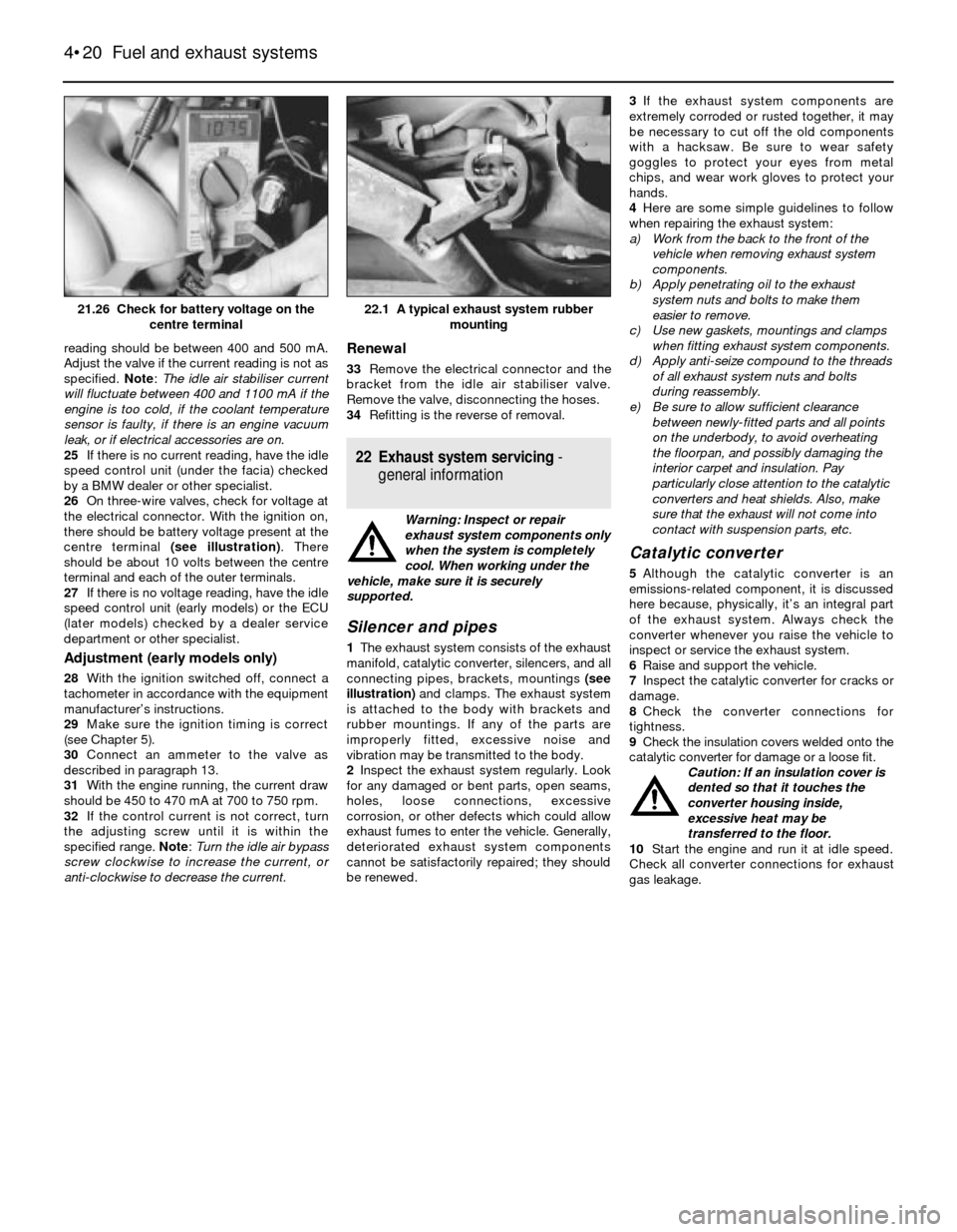
centre terminal (see illustration). There
should be about 10 volts between the centre
terminal and each of the outer terminals.
27If there is no voltage reading, have the idle
speed control unit (early models) or the ECU
(later models) checked by a dealer service
department or other specialist.
Adjustment (early models only)
28With the ignition switched off, connect a
tachometer in accordance with the equipment
manufacturer’s instructions.
29Make sure the ignition timing is correct
(see Chapter 5).
30Connect an ammeter to the valve as
described in paragraph 13.
31With the engine running, the current draw
should be 450 to 470 mA at 700 to 750 rpm.
32If the control current is not correct, turn
the adjusting screw until it is within the
specified range. Note: Turn the idle air bypass
screw clockwise to increase the current, or
anti-clockwise to decrease the current.
Renewal
33Remove the electrical connector and the
bracket from the idle air stabiliser valve.
Remove the valve, disconnecting the hoses.
34Refitting is the reverse of removal.
22 Exhaust system servicing-
general information
Warning: Inspect or repair
exhaust system components only
when the system is completely
cool. When working under the
vehicle, make sure it is securely
supported.
Silencer and pipes
1The exhaust system consists of the exhaust
manifold, catalytic converter, silencers, and all
connecting pipes, brackets, mountings (see
illustration)and clamps. The exhaust system
is attached to the body with brackets and
rubber mountings. If any of the parts are
improperly fitted, excessive noise and
vibration may be transmitted to the body.
2Inspect the exhaust system regularly. Look
for any damaged or bent parts, open seams,
holes, loose connections, excessive
corrosion, or other defects which could allow
exhaust fumes to enter the vehicle. Generally,
deteriorated exhaust system components
cannot be satisfactorily repaired; they should
be renewed.3If the exhaust system components are
extremely corroded or rusted together, it may
be necessary to cut off the old components
with a hacksaw. Be sure to wear safety
goggles to protect your eyes from metal
chips, and wear work gloves to protect your
hands.
4Here are some simple guidelines to follow
when repairing the exhaust system:
a) Work from the back to the front of the
vehicle when removing exhaust system
components.
b) Apply penetrating oil to the exhaust
system nuts and bolts to make them
easier to remove.
c) Use new gaskets, mountings and clamps
when fitting exhaust system components.
d) Apply anti-seize compound to the threads
of all exhaust system nuts and bolts
during reassembly.
e) Be sure to allow sufficient clearance
between newly-fitted parts and all points
on the underbody, to avoid overheating
the floorpan, and possibly damaging the
interior carpet and insulation. Pay
particularly close attention to the catalytic
converters and heat shields. Also, make
sure that the exhaust will not come into
contact with suspension parts, etc.
Catalytic converter
5Although the catalytic converter is an
emissions-related component, it is discussed
here because, physically, it’s an integral part
of the exhaust system. Always check the
converter whenever you raise the vehicle to
inspect or service the exhaust system.
6Raise and support the vehicle.
7Inspect the catalytic converter for cracks or
damage.
8Check the converter connections for
tightness.
9Check the insulation covers welded onto the
catalytic converter for damage or a loose fit.
Caution: If an insulation cover is
dented so that it touches the
converter housing inside,
excessive heat may be
transferred to the floor.
10Start the engine and run it at idle speed.
Check all converter connections for exhaust
gas leakage.
4•20 Fuel and exhaust systems
22.1 A typical exhaust system rubber
mounting21.26 Check for battery voltage on the
centre terminal
Page 119 of 228
Withdraw the sensor from its bracket and
remove it.
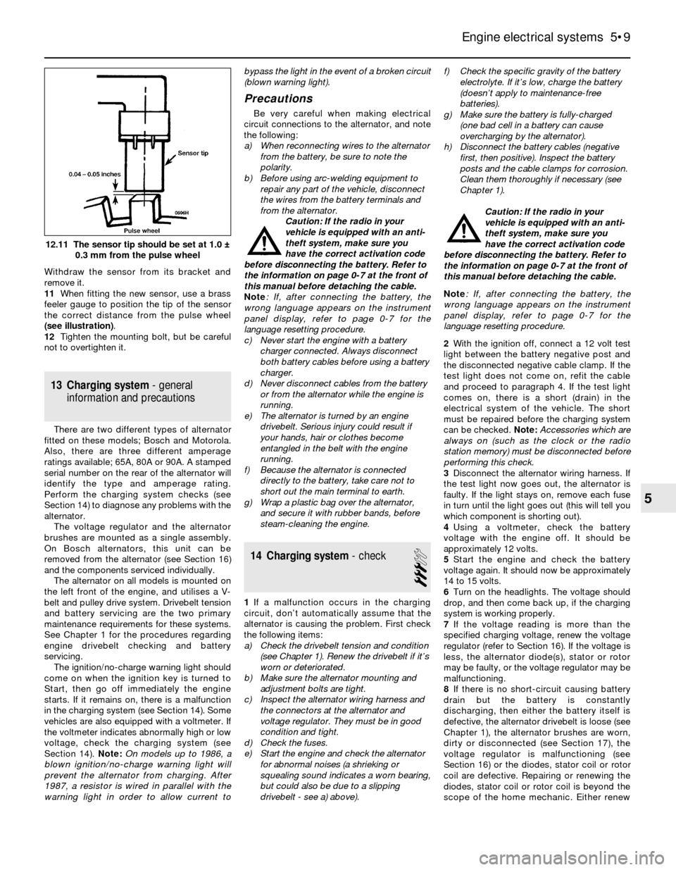
11When fitting the new sensor, use a brass
feeler gauge to position the tip of the sensor
the correct distance from the pulse wheel
(see illustration).
12Tighten the mounting bolt, but be careful
not to overtighten it.
13 Charging system- general
information and precautions
There are two different types of alternator
fitted on these models; Bosch and Motorola.
Also, there are three different amperage
ratings available; 65A, 80A or 90A. A stamped
serial number on the rear of the alternator will
identify the type and amperage rating.
Perform the charging system checks (see
Section 14) to diagnose any problems with the
alternator.
The voltage regulator and the alternator
brushes are mounted as a single assembly.
On Bosch alternators, this unit can be
removed from the alternator (see Section 16)
and the components serviced individually.
The alternator on all models is mounted on
the left front of the engine, and utilises a V-
belt and pulley drive system. Drivebelt tension
and battery servicing are the two primary
maintenance requirements for these systems.
See Chapter 1 for the procedures regarding
engine drivebelt checking and battery
servicing.
The ignition/no-charge warning light should
come on when the ignition key is turned to
Start, then go off immediately the engine
starts. If it remains on, there is a malfunction
in the charging system (see Section 14). Some
vehicles are also equipped with a voltmeter. If
the voltmeter indicates abnormally high or low
voltage, check the charging system (see
Section 14). Note:On models up to 1986, a
blown ignition/no-charge warning light will
prevent the alternator from charging. After
1987, a resistor is wired in parallel with the
warning light in order to allow current tobypass the light in the event of a broken circuit
(blown warning light).
Precautions
Be very careful when making electrical
circuit connections to the alternator, and note
the following:
a) When reconnecting wires to the alternator
from the battery, be sure to note the
polarity.
b) Before using arc-welding equipment to
repair any part of the vehicle, disconnect
the wires from the battery terminals and
from the alternator.
Caution: If the radio in your
vehicle is equipped with an anti-
theft system, make sure you
have the correct activation code
before disconnecting the battery. Refer to
the information on page 0-7 at the front of
this manual before detaching the cable.
Note: If, after connecting the battery, the
wrong language appears on the instrument
panel display, refer to page 0-7 for the
language resetting procedure.
c) Never start the engine with a battery
charger connected. Always disconnect
both battery cables before using a battery
charger.
d) Never disconnect cables from the battery
or from the alternator while the engine is
running.
e) The alternator is turned by an engine
drivebelt. Serious injury could result if
your hands, hair or clothes become
entangled in the belt with the engine
running.
f) Because the alternator is connected
directly to the battery, take care not to
short out the main terminal to earth.
g) Wrap a plastic bag over the alternator,
and secure it with rubber bands, before
steam-cleaning the engine.
14 Charging system- check
3
1If a malfunction occurs in the charging
circuit, don’t automatically assume that the
alternator is causing the problem. First check
the following items:
a) Check the drivebelt tension and condition
(see Chapter 1). Renew the drivebelt if it’s
worn or deteriorated.
b) Make sure the alternator mounting and
adjustment bolts are tight.
c) Inspect the alternator wiring harness and
the connectors at the alternator and
voltage regulator. They must be in good
condition and tight.
d) Check the fuses.
e) Start the engine and check the alternator
for abnormal noises (a shrieking or
squealing sound indicates a worn bearing,
but could also be due to a slipping
drivebelt - see a) above).f) Check the specific gravity of the battery
electrolyte. If it’s low, charge the battery
(doesn’t apply to maintenance-free
batteries).
g) Make sure the battery is fully-charged
(one bad cell in a battery can cause
overcharging by the alternator).
h) Disconnect the battery cables (negative
first, then positive). Inspect the battery
posts and the cable clamps for corrosion.
Clean them thoroughly if necessary (see
Chapter 1).
Caution: If the radio in your
vehicle is equipped with an anti-
theft system, make sure you
have the correct activation code
before disconnecting the battery. Refer to
the information on page 0-7 at the front of
this manual before detaching the cable.
Note: If, after connecting the battery, the
wrong language appears on the instrument
panel display, refer to page 0-7 for the
language resetting procedure.
2With the ignition off, connect a 12 volt test
light between the battery negative post and
the disconnected negative cable clamp. If the
test light does not come on, refit the cable
and proceed to paragraph 4. If the test light
comes on, there is a short (drain) in the
electrical system of the vehicle. The short
must be repaired before the charging system
can be checked. Note: Accessories which are
always on (such as the clock or the radio
station memory) must be disconnected before
performing this check.
3Disconnect the alternator wiring harness. If
the test light now goes out, the alternator is
faulty. If the light stays on, remove each fuse
in turn until the light goes out (this will tell you
which component is shorting out).
4Using a voltmeter, check the battery
voltage with the engine off. It should be
approximately 12 volts.
5Start the engine and check the battery
voltage again. It should now be approximately
14 to 15 volts.
6Turn on the headlights. The voltage should
drop, and then come back up, if the charging
system is working properly.
7If the voltage reading is more than the
specified charging voltage, renew the voltage
regulator (refer to Section 16). If the voltage is
less, the alternator diode(s), stator or rotor
may be faulty, or the voltage regulator may be
malfunctioning.
8If there is no short-circuit causing battery
drain but the battery is constantly
discharging, then either the battery itself is
defective, the alternator drivebelt is loose (see
Chapter 1), the alternator brushes are worn,
dirty or disconnected (see Section 17), the
voltage regulator is malfunctioning (see
Section 16) or the diodes, stator coil or rotor
coil are defective. Repairing or renewing the
diodes, stator coil or rotor coil is beyond the
scope of the home mechanic. Either renew
Engine electrical systems 5•9
12.11 The sensor tip should be set at 1.0 ±
0.3 mm from the pulse wheel
5
Page 140 of 228
and push it through until the forward end
comes out at the handbrake lever.
8Insert the cable conduit through the
backplate, and attach the rear end of the
cable to the handbrake lever (rear drum
models) or the actuator (rear disc models).
Make sure you don’t kink the cable while
connecting it.
9Refit the cable conduit to the clips on the
back of the trailing arm.
10On rear drum models, refit the brake
shoes and drum (see Section 6). On rear disc
models, refit the handbrake shoes and
actuator (see Section 12) and the rear brake
disc (see Section 5).
11Lower the vehicle, and refit the adjusting
nut at the handbrake lever. Adjust the
handbrake cable (see Section 11) and refit the
handbrake lever boot.
11 Handbrake- adjustment
2
Rear drum brake models
Note:Adjustment of the handbrake cable(s)
on models with rear drum brakes should only
be necessary when you renew a cable or
detach if from the rear brake assembly for
some reason. Failure of the handbrake system
to hold the vehicle usually indicates worn
brake shoes or a faulty self-adjusting
mechanism.
1Raise the rear of the vehicle, and place it
securely on axle stands.
2Fully release the handbrake lever, then
apply the brakes firmly several times with the
footbrake pedal.
3Pull the handbrake lever up five clicks.
4Tighten or loosen the adjusting nuts by
equal amounts until the rear brake shoes just
begin to drag on the brake drum. You should
feel the same amount of resistance at both
wheels when you rotate them.
5Release the handbrake lever, and verify that
the wheels rotate freely. If they don’t, re-
adjust them.
Rear disc brake models
Note: The handbrake system is not self-
adjusting on models with rear disc brakes. The
handbrake therefore requires periodic
adjustment to compensate for wear. It should
also be adjusted anytime either cable, brake
disc or handbrake assembly is renewed or
removed for some reason.
6Slowly apply the handbrake, and count the
number of clicks at the lever. If the lever can
be pulled up further than the eighth click,
adjust the handbrake cable as follows.
7Peel back the handbrake lever boot, and
loosen the cable adjusting nut (see
illustration 10.1). On some models, it may be
necessary to remove the centre console
completely for access.
8Loosen a single bolt in each rear wheel.Raise the vehicle and place it securely on axle
stands.
9Remove the bolt you loosened in each rear
wheel. Turn the wheel until, using a torch, you
can see the adjuster starwheel through the
bolt hole.
10Turn the adjuster - clockwise to expand
the shoes, anti-clockwise to retract them -
until the brake shoes just contact the brake
drum (see illustration 5.6d). Back off the
brake shoes so the wheel spins freely (three to
four teeth on the adjuster). Note:If the
adjuster starwheel is hard to turn, remove the
wheel and brake disc, lubricate the adjuster
wheel, and try again.
11With the disc fitted, apply the handbrake
three times to stretch and seat the cables,
then slowly pull up on the handbrake lever to
the fifth click. Tighten the cable adjusting nuts
by equal amounts until the rear brake shoes
just touch the brake drum. Verify that both
wheels have the same amount of resistance.
12Release the handbrake, and verify that
both rear wheels rotate freely.
13Tighten the wheel bolts to the torque
listed in Chapter 1 Specifications.
12 Handbrake assembly-
check, removal and refitting
2
Warning: The handbrake linings
on rear disc brake models may
be manufactured of asbestos-
based material. Refer to the
warning at the start of Section 6. When
servicing these components, do not create
dust by grinding or sanding the linings.
1The handbrake system should be checked
regularly. With the vehicle parked on a hill,
apply the handbrake, select neutral, and
check that the handbrake alone will hold the
vehicle when the footbrake is released (be
sure to stay in the vehicle during this check).
However, every 2 years (or whenever a fault is
suspected), the assembly itself should be
inspected.
2With the vehicle raised and supported onaxle stands, remove the rear wheels.
3On rear brake drum models, refer to
Chapter 1; checking the thickness of the
brake shoes is a routine maintenance
procedure.
4On rear disc brake models, remove the rear
discs as outlined in Section 5. Support the
caliper assemblies with a coat hanger or
heavy wire; do not disconnect the brake line
from the caliper.
5With the disc removed, the handbrake
components are visible, and can be inspected
for wear and damage. The linings should last
the life of the vehicle. However, they can wear
down if the handbrake system has been
improperly adjusted, or if the handbrake is
regularly used to stop the vehicle. There is no
minimum thickness specification for the
handbrake shoes, but as a rule of thumb, if
the shoe material is less than 1.5 mm thick,
you should renew them. Also check the
springs and adjuster mechanism and inspect
the drum for deep scratches and other
damage.
Removal and refitting
Note:The following procedure applies only to
models with rear disc brakes. The handbrake
system on models with rear drum brakes is an
integral part of the rear brake assembly (see
Section 6).
6Loosen the rear wheel bolts, raise the rear
of the vehicle and place it securely on axle
stands. Remove the rear wheels. Remove the
brake discs (see Section 5). Work on only one
side at a time, so you can use the other side
as a reference during reassembly, and to
avoid mixing up parts.
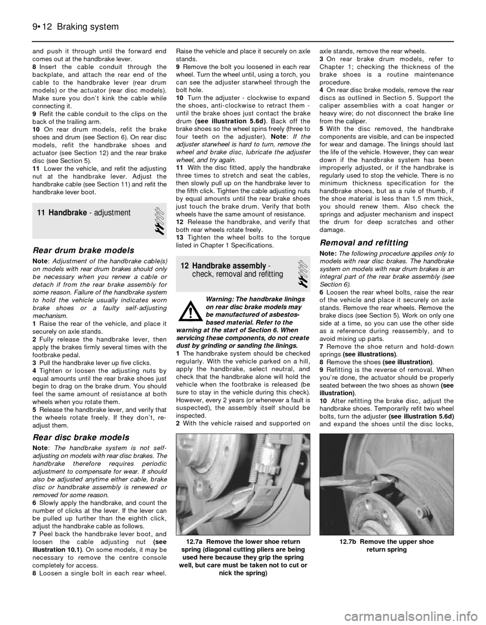
7Remove the shoe return and hold-down
springs (see illustrations).
8Remove the shoes (see illustration).
9Refitting is the reverse of removal. When
you’re done, the actuator should be properly
seated between the two shoes as shown (see
illustration).
10After refitting the brake disc, adjust the
handbrake shoes. Temporarily refit two wheel
bolts, turn the adjuster (see illustration 5.6d)
and expand the shoes until the disc locks,
9•12 Braking system
12.7b Remove the upper shoe
return spring12.7a Remove the lower shoe return
spring (diagonal cutting pliers are being
used here because they grip the spring
well, but care must be taken not to cut or
nick the spring)
Page 167 of 228
15 Latch, lock cylinder and
handles- removal, refitting
and adjustment
1
1Remove the trim panel(s) and, on the door,
the plastic shield (see Section 12).
Latch
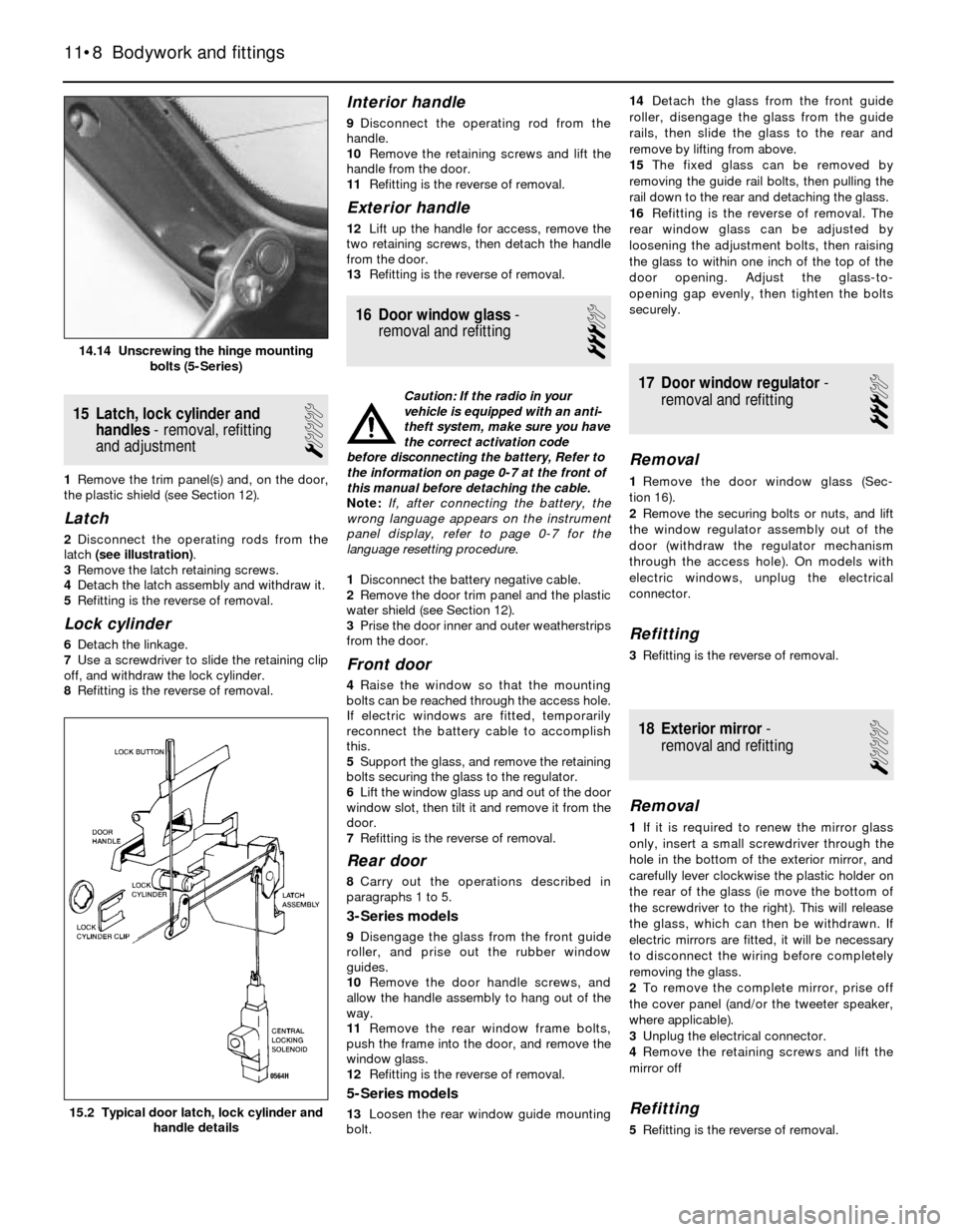
2Disconnect the operating rods from the
latch (see illustration).
3Remove the latch retaining screws.
4Detach the latch assembly and withdraw it.
5Refitting is the reverse of removal.
Lock cylinder
6Detach the linkage.
7Use a screwdriver to slide the retaining clip
off, and withdraw the lock cylinder.
8Refitting is the reverse of removal.
Interior handle
9Disconnect the operating rod from the
handle.
10Remove the retaining screws and lift the
handle from the door.
11Refitting is the reverse of removal.
Exterior handle
12Lift up the handle for access, remove the
two retaining screws, then detach the handle
from the door.
13Refitting is the reverse of removal.
16 Door window glass-
removal and refitting
3
Caution: If the radio in your
vehicle is equipped with an anti-
theft system, make sure you have
the correct activation code
before disconnecting the battery, Refer to
the information on page 0-7 at the front of
this manual before detaching the cable.
Note: If, after connecting the battery, the
wrong language appears on the instrument
panel display, refer to page 0-7 for the
language resetting procedure.
1Disconnect the battery negative cable.
2Remove the door trim panel and the plastic
water shield (see Section 12).
3Prise the door inner and outer weatherstrips
from the door.
Front door
4Raise the window so that the mounting
bolts can be reached through the access hole.
If electric windows are fitted, temporarily
reconnect the battery cable to accomplish
this.
5Support the glass, and remove the retaining
bolts securing the glass to the regulator.
6Lift the window glass up and out of the door
window slot, then tilt it and remove it from the
door.
7Refitting is the reverse of removal.
Rear door
8Carry out the operations described in
paragraphs 1 to 5.
3-Series models
9Disengage the glass from the front guide
roller, and prise out the rubber window
guides.
10Remove the door handle screws, and
allow the handle assembly to hang out of the
way.
11Remove the rear window frame bolts,
push the frame into the door, and remove the
window glass.
12Refitting is the reverse of removal.
5-Series models
13Loosen the rear window guide mounting
bolt.14Detach the glass from the front guide
roller, disengage the glass from the guide
rails, then slide the glass to the rear and
remove by lifting from above.
15The fixed glass can be removed by
removing the guide rail bolts, then pulling the
rail down to the rear and detaching the glass.
16Refitting is the reverse of removal. The
rear window glass can be adjusted by
loosening the adjustment bolts, then raising
the glass to within one inch of the top of the
door opening. Adjust the glass-to-
opening gap evenly, then tighten the bolts
securely.
17 Door window regulator-
removal and refitting
3
Removal
1Remove the door window glass (Sec-
tion 16).
2Remove the securing bolts or nuts, and lift
the window regulator assembly out of the
door (withdraw the regulator mechanism
through the access hole). On models with
electric windows, unplug the electrical
connector.
Refitting
3Refitting is the reverse of removal.
18 Exterior mirror-
removal and refitting
1
Removal
1If it is required to renew the mirror glass
only, insert a small screwdriver through the
hole in the bottom of the exterior mirror, and
carefully lever clockwise the plastic holder on
the rear of the glass (ie move the bottom of
the screwdriver to the right). This will release
the glass, which can then be withdrawn. If
electric mirrors are fitted, it will be necessary
to disconnect the wiring before completely
removing the glass.
2To remove the complete mirror, prise off
the cover panel (and/or the tweeter speaker,
where applicable).
3Unplug the electrical connector.
4Remove the retaining screws and lift the
mirror off
Refitting
5Refitting is the reverse of removal.
11•8 Bodywork and fittings
15.2 Typical door latch, lock cylinder and
handle details
14.14 Unscrewing the hinge mounting
bolts (5-Series)
Page 174 of 228
13 Headlights- adjustment
2
Note:The headlights must be aimed correctly.
If adjusted incorrectly, they could momentarily
blind the driver of an oncoming vehicle and
cause a serious accident, or seriously reduce
your ability to see the road. The headlights
should be checked for proper aim every
12 months (as is done during the MOT test),
and any time a new headlight is fitted or front-
end body work is performed. It should be
emphasised that the following procedure will
only provide a temporary setting until the
headlights can be adjusted by a properly-
equipped garage.
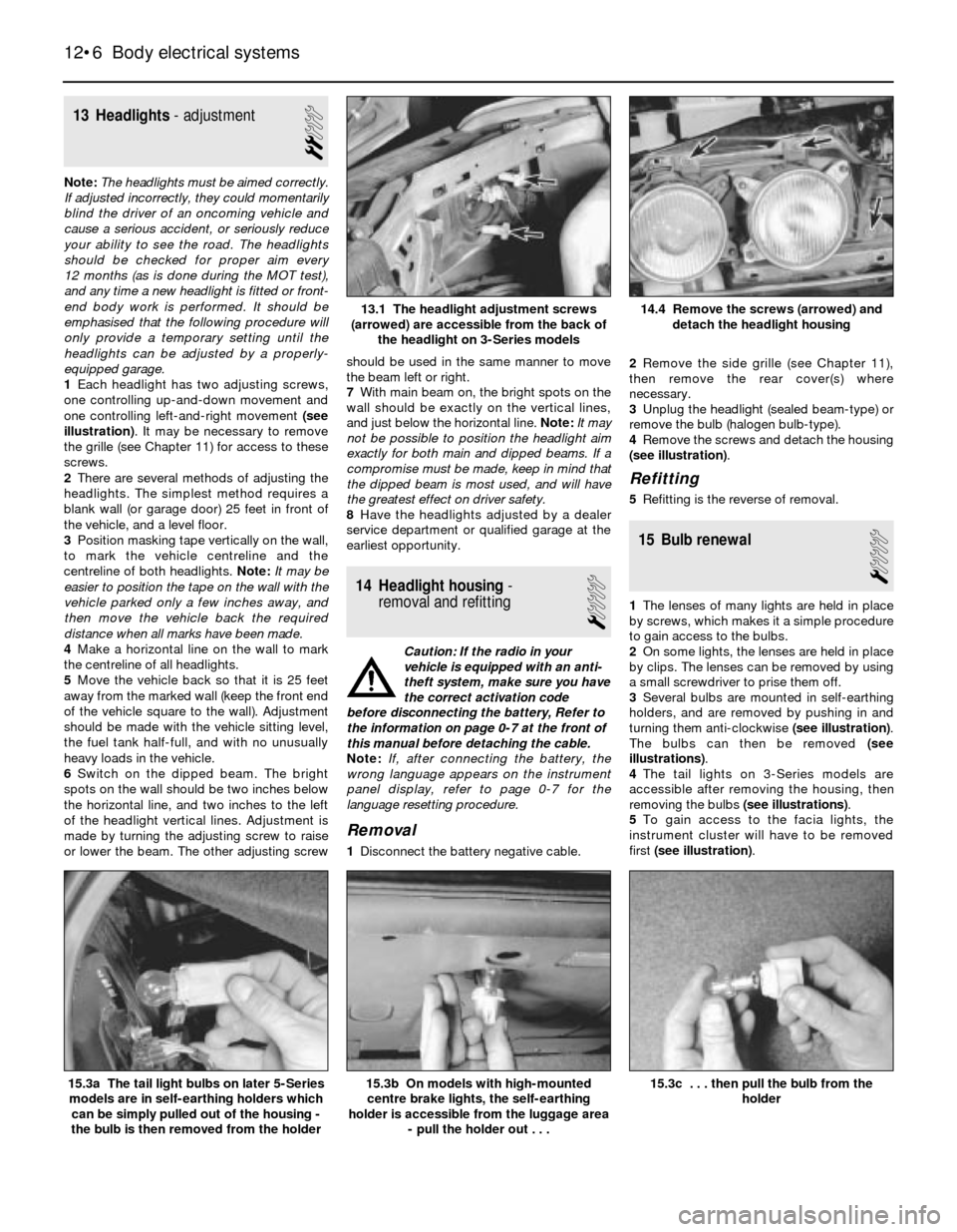
1Each headlight has two adjusting screws,
one controlling up-and-down movement and
one controlling left-and-right movement (see
illustration). It may be necessary to remove
the grille (see Chapter 11) for access to these
screws.
2There are several methods of adjusting the
headlights. The simplest method requires a
blank wall (or garage door) 25 feet in front of
the vehicle, and a level floor.
3Position masking tape vertically on the wall,
to mark the vehicle centreline and the
centreline of both headlights. Note:It may be
easier to position the tape on the wall with the
vehicle parked only a few inches away, and
then move the vehicle back the required
distance when all marks have been made.
4Make a horizontal line on the wall to mark
the centreline of all headlights.
5Move the vehicle back so that it is 25 feet
away from the marked wall (keep the front end
of the vehicle square to the wall). Adjustment
should be made with the vehicle sitting level,
the fuel tank half-full, and with no unusually
heavy loads in the vehicle.
6Switch on the dipped beam. The bright
spots on the wall should be two inches below
the horizontal line, and two inches to the left
of the headlight vertical lines. Adjustment is
made by turning the adjusting screw to raise
or lower the beam. The other adjusting screwshould be used in the same manner to move
the beam left or right.
7With main beam on, the bright spots on the
wall should be exactly on the vertical lines,
and just below the horizontal line. Note:It may
not be possible to position the headlight aim
exactly for both main and dipped beams. If a
compromise must be made, keep in mind that
the dipped beam is most used, and will have
the greatest effect on driver safety.
8Have the headlights adjusted by a dealer
service department or qualified garage at the
earliest opportunity.
14 Headlight housing-
removal and refitting
1
Caution: If the radio in your
vehicle is equipped with an anti-
theft system, make sure you have
the correct activation code
before disconnecting the battery, Refer to
the information on page 0-7 at the front of
this manual before detaching the cable.
Note: If, after connecting the battery, the
wrong language appears on the instrument
panel display, refer to page 0-7 for the
language resetting procedure.
Removal
1Disconnect the battery negative cable.2Remove the side grille (see Chapter 11),
then remove the rear cover(s) where
necessary.
3Unplug the headlight (sealed beam-type) or
remove the bulb (halogen bulb-type).
4Remove the screws and detach the housing
(see illustration).
Refitting
5Refitting is the reverse of removal.
15 Bulb renewal
1
1The lenses of many lights are held in place
by screws, which makes it a simple procedure
to gain access to the bulbs.
2On some lights, the lenses are held in place
by clips. The lenses can be removed by using
a small screwdriver to prise them off.
3Several bulbs are mounted in self-earthing
holders, and are removed by pushing in and
turning them anti-clockwise (see illustration).
The bulbs can then be removed (see
illustrations).
4The tail lights on 3-Series models are
accessible after removing the housing, then
removing the bulbs (see illustrations).
5To gain access to the facia lights, the
instrument cluster will have to be removed
first (see illustration).
12•6 Body electrical systems
15.3c . . . then pull the bulb from the
holder15.3b On models with high-mounted
centre brake lights, the self-earthing
holder is accessible from the luggage area
- pull the holder out . . .15.3a The tail light bulbs on later 5-Series
models are in self-earthing holders which
can be simply pulled out of the housing -
the bulb is then removed from the holder
14.4 Remove the screws (arrowed) and
detach the headlight housing13.1 The headlight adjustment screws
(arrowed) are accessible from the back of
the headlight on 3-Series models
Page 175 of 228
16 Windscreen/tailgate wiper
motor- removal and refitting
2
Caution: If the radio in your
vehicle is equipped with an anti-
theft system, make sure you have
the correct activation code
before disconnecting the battery, Refer to
the information on page 0-7 at the front of
this manual before detaching the cable.
Note: If, after connecting the battery, the
wrong language appears on the instrument
panel display, refer to page 0-7 for the
language resetting procedure.
1Disconnect the battery negative cable.
Windscreen wiper motor
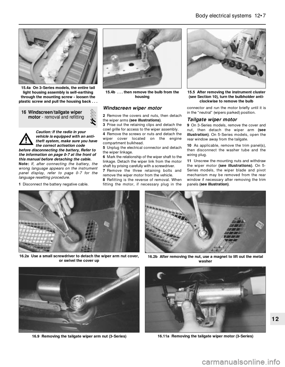
2Remove the covers and nuts, then detach
the wiper arms (see illustrations).
3Prise out the retaining clips and detach the
cowl grille for access to the wiper assembly.
4Remove the screws or nuts and detach the
wiper cover located on the engine
compartment bulkhead.
5Unplug the electrical connector and detach
the wiper linkage.
6Mark the relationship of the wiper shaft to the
linkage. Detach the wiper link from the motor
shaft by prising carefully with a screwdriver.
7Remove the three retaining bolts and
remove the wiper motor from the vehicle.
8Refitting is the reverse of removal. When
fitting the motor, if necessary plug in theconnector and run the motor briefly until it is
in the “neutral” (wipers parked) position.Tailgate wiper motor
9On 3-Series models, remove the cover and
nut, then detach the wiper arm (see
illustration). On 5-Series models, open the
rear window away from the tailgate.
10As applicable, remove the trim panel(s),
then disconnect the washer tube and the
wiring plug.
11Unscrew the mounting nuts and withdraw
the wiper motor (see illustrations). On 5-
Series models, the wiper blade and pivot
mechanism may be removed from the rear
window if necessary after removing the trim
panels (see illustration).
Body electrical systems 12•7
15.5 After removing the instrument cluster
(see Section 10), turn the bulbholder anti-
clockwise to remove the bulb15.4b . . . then remove the bulb from the
housing15.4a On 3-Series models, the entire tail
light housing assembly is self-earthing
through the mounting screw - loosen the
plastic screw and pull the housing back . . .
16.11a Removing the tailgate wiper motor (3-Series)
16.2b After removing the nut, use a magnet to lift out the metal
washer16.2a Use a small screwdriver to detach the wiper arm nut cover,
or swivel the cover up
16.9 Removing the tailgate wiper arm nut (3-Series)
12
Page 186 of 228

12•18 Wiring diagrams
Typical wiring diagram for the central locking, burglar alarm, on-board computer, additional heater and digital clock (1 of 2)
Page 187 of 228

Wiring diagrams 12•19
12
Typical wiring diagram for the central locking, burglar alarm, on-board computer, additional heater and digital clock (2 of 2)