change wheel BMW 428I CONVERTIBLE 2016 User Guide
[x] Cancel search | Manufacturer: BMW, Model Year: 2016, Model line: 428I CONVERTIBLE, Model: BMW 428I CONVERTIBLE 2016Pages: 247, PDF Size: 5.22 MB
Page 108 of 247

sequent vehicle start-ups as long as the mal‐
function exists. When the malfunction indicator
is illuminated, the system may not be able to
detect or signal low tire pressure as intended.
TPMS malfunctions may occur for a variety of
reasons, including the installation of replace‐
ment or alternate tires or wheels on the vehicle
that prevent the TPMS from functioning prop‐
erly. Always check the TPMS malfunction tell‐
tale after replacing one or more tires or wheels
on your vehicle to ensure that the replacement
or alternate tires and wheels allow the TPMS
to continue to function properly.
FTM Flat Tire Monitor The conceptThe system detects tire inflation pressure losson the basis of rotation speed differences be‐
tween the individual wheels while driving.
In the event of a tire inflation pressure loss, the
diameter and therefore the rotational speed of
the corresponding wheel changes. This will be
detected and reported as a flat tire.
The system does not measure the actual infla‐
tion pressure in the tires.
Functional requirements
The system must have been initialized when
the tire inflation pressure was correct; other‐
wise, reliable flagging of a flat tire is not as‐
sured. Initialize the system after each correc‐ tion of the tire inflation pressure and after
every tire or wheel change.
Status display
The current status of the Flat Tire Monitor can
be displayed on the Control Display, e.g.,
whether or not the FTM is active.
On the Control Display:1."Vehicle info"2."Vehicle status"3. "Flat Tire Monitor (FTM)"The status is displayed.
Initialization
When initializing the once set inflation tire
pressures serve as reference values in order to
detect a flat tire. Initialization is started by con‐
firming the tire inflation pressures.
Do not initialize the system when driving with
snow chains.
On the Control Display:1."Vehicle info"2."Vehicle status"3. "Perform reset"4.Start the engine - do not drive off.5.Start the initialization with "Perform reset".6.Drive away.
The initialization is completed while driving,
which can be interrupted at any time.
The initialization automatically continues when
driving resumes.
Indication of a flat tire The yellow warning lamp lights up. A
Check Control message is displayed.
There is a flat tire or a major loss in tire
inflation pressure.
1.Reduce your speed and stop cautiously.
Avoid sudden braking and steering maneu‐
vers.2.Check whether the vehicle is fitted with
regular tires or run-flat tires.
Run-flat tires, refer to page 194, are la‐
beled with a circular symbol containing the
letters RSC marked on the tire's sidewall.
Do not continue driving without run-flat
tires
Do not continue driving if the vehicle is not
equipped with run-flat tires; continued driving
may result in serious accidents.◀
Seite 104ControlsSafety104
Online Edition for Part no. 01 40 2 960 547 - II/15
Page 120 of 247

▷When using the turn signal.
System limits
The system may not be fully functional in the
following situations:
▷In heavy fog, rain or snowfall.▷In the event of missing, worn, poorly visi‐
ble, merging, diverging, or multiple lane
markings such as in construction areas.▷When lane markings are covered in snow,
ice, dirt or water.▷In tight curves or on narrow lanes.▷When the lane markings are covered by
objects.▷When driving very close to the vehicle in
front of you.▷When driving toward bright lights.▷When the windshield in front of the interior
rearview mirror is fogged over, dirty or cov‐
ered with stickers, etc.▷During calibration of the camera immedi‐
ately after vehicle shipment.
Active Blind Spot Detection
The concept
Two radar sensors below the rear bumper
monitor the area behind and next to the vehicle
at speeds above approx. 30 mph/50 km/h.
The system indicates whether there are vehi‐
cles in the blind spot, arrow 1, or approaching
from behind on the adjacent lane, arrow 2.
The lamp in the exterior mirror housing is dim‐
med.
Before you change lanes after setting the turn
signal, the system issues a warning in the sit‐
uations described above.
The lamp in the exterior mirror housing flashes
and the steering wheel vibrates.
Hints Personal responsibility
The system does not serve as a substi‐
tute for the driver's personal judgment of the
traffic situation.
Be aware of the traffic situation and the vehi‐
cle's surroundings at all times, otherwise acci‐
dents are still possible despite all warnings.◀
At a glance
Button in the vehicle
Active Blind Spot Detection
Seite 116ControlsSafety116
Online Edition for Part no. 01 40 2 960 547 - II/15
Page 121 of 247

Radar sensors
The radar sensors are located under the rear
bumper.
Switching on/off Press button.
▷On: the LED lights up.▷Off: the LED goes out.
Settings are stored for the profile currently in
use.
Display
Lamp in the exterior mirror housing
Information stage
The dimmed lamp in the exterior mirror hous‐
ing indicates when there are vehicles in the
blind spot or approaching from behind.
Warning If the turn signal is set while a vehicle is in the
critical zone, the steering wheel vibrates briefly
and the lamp in the exterior mirror housing
flashes brightly.
The warning stops when the turn signal is
switched off, or the other vehicle leaves the
critical zone.
System limits
The system may not be fully functional in the
following situations:▷When a vehicle is approaching at a speed
much faster than your own.▷In heavy fog, rain or snowfall.▷In tight curves or on narrow lanes.▷If the bumper is dirty or iced up, or covered
with stickers.
A Check Control message is displayed when
the system is not fully functional.
For US owners only The transmitter and receiver units comply with
part 15 of the FCC/Federal Communication
Commission regulations. Operation is gov‐
erned by the following:
FCC ID:
▷NBG009014A.
Compliance statement:
This device complies with part 15 of the FCC
Rules. Operation is subject to the following
two conditions:
▷This device may not cause harmful inter‐
ference, and▷this device must accept any interference
received, including interference that may
cause undesired operation.
Any unauthorized modifications or changes to
these devices could void the user's authority to
operate this equipment.
Seite 117SafetyControls117
Online Edition for Part no. 01 40 2 960 547 - II/15
Page 125 of 247

Dynamic Damping Control
The concept This system reduces undesirable vehicle mo‐
tion when using a dynamic driving style or trav‐
eling on uneven road surfaces.
The system enhances driving dynamics and
comfort fitting road surface and driving style.
Programs The system offers several different programs.
Select the programs via the Driving Dynamics
Control, refer to page 121.
SPORT
Consistently sporty control of the shock ab‐
sorbers for greater driving agility.
SPORT+ Consistently sporty control of the shock ab‐
sorbers for greater driving agility when driving
with limited driving stabilization.
COMFORT/ECO PRO
Balanced control of the vehicle.
Variable sport steering The variable sport steering increases the
steering angle of the front wheels at large
steering wheel angles, e.g., in tight curves or
when parking. Steering becomes more direct.
It also varies the force required to turn the
wheels in accordance with the vehicle speed.
This results in a sporty steering response. In
addition, it becomes easier to steer during
parking and maneuvering.Driving Dynamics Control
The conceptThe Driving Dynamics Control helps to fine-
tune the vehicle's settings and features. Vari‐
ous programs can be selected for this purpose.
The Driving Dynamics Control and the DSC
OFF buttons can each be used to activate a
program.
Overview
Button in the vehicle
Operating the programs
Press buttonProgramDSC OFF
TRACTIONSPORT+
SPORT
COMFORT
ECO PRO
Automatic program change
The system may automatically switch to COM‐
FORT in the following situations:
▷Failure of Dynamic Damping Control.▷Failure of DSC Dynamic Stability Control.▷The vehicle has a flat tire.▷When activating cruise control in TRAC‐
TION or DSC OFF mode.Seite 121Driving stability control systemsControls121
Online Edition for Part no. 01 40 2 960 547 - II/15
Page 127 of 247
The program can be configured to individual
specifications.
Activating ECO PRO Press button repeatedly until ECO
PRO is displayed in the instrument
cluster.
Configuring ECO PRO1.Activate ECO PRO.2."Configure ECO PRO"
Make the desired settings.
Configuring driving program Settings can be made for the following driving
programs in Driving mode:
▷SPORT, refer to page 122.▷ECO PRO, refer to page 175.
Displays
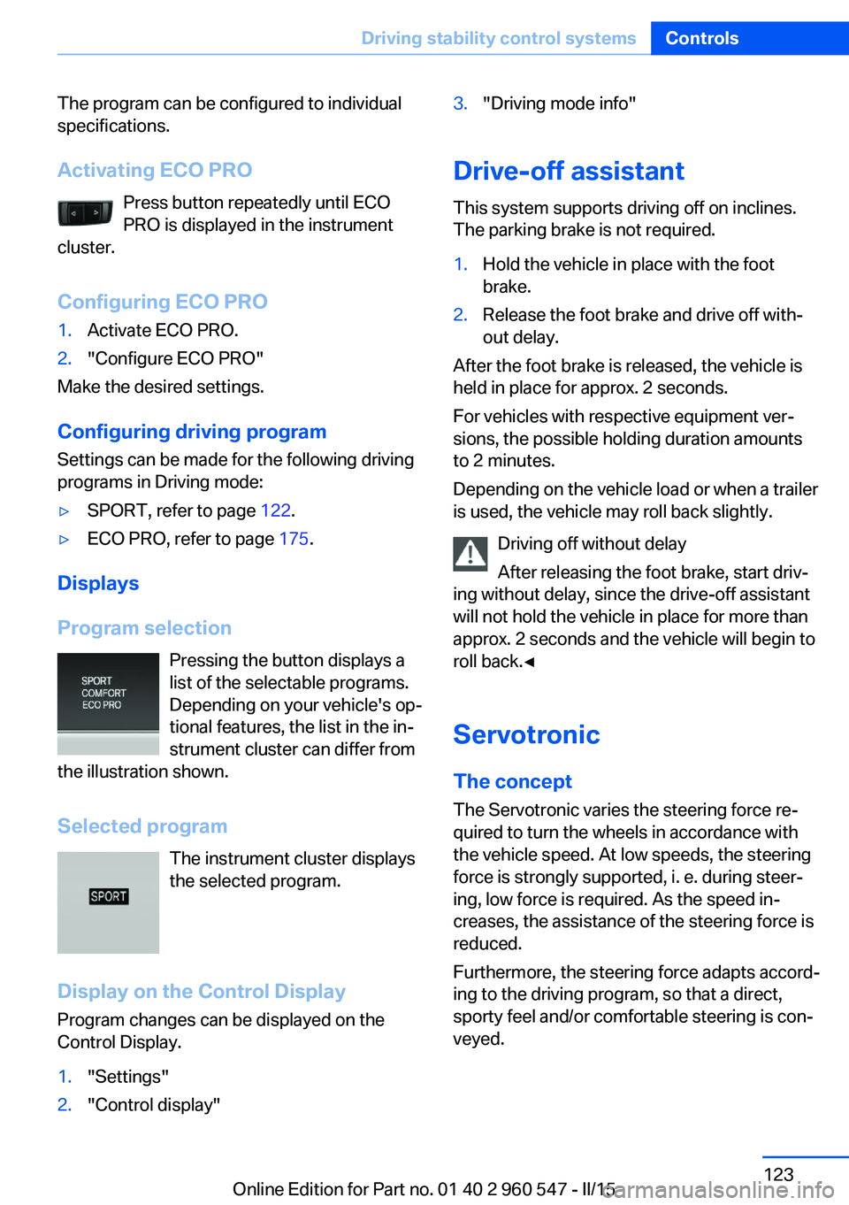
Program selection Pressing the button displays a
list of the selectable programs.
Depending on your vehicle's op‐
tional features, the list in the in‐
strument cluster can differ from
the illustration shown.
Selected program The instrument cluster displays
the selected program.
Display on the Control Display Program changes can be displayed on the
Control Display.
1."Settings"2."Control display"3."Driving mode info"
Drive-off assistant
This system supports driving off on inclines.
The parking brake is not required.
1.Hold the vehicle in place with the foot
brake.2.Release the foot brake and drive off with‐
out delay.
After the foot brake is released, the vehicle is
held in place for approx. 2 seconds.
For vehicles with respective equipment ver‐
sions, the possible holding duration amounts
to 2 minutes.
Depending on the vehicle load or when a trailer
is used, the vehicle may roll back slightly.
Driving off without delay
After releasing the foot brake, start driv‐
ing without delay, since the drive-off assistant
will not hold the vehicle in place for more than
approx. 2 seconds and the vehicle will begin to
roll back.◀
Servotronic The conceptThe Servotronic varies the steering force re‐
quired to turn the wheels in accordance with
the vehicle speed. At low speeds, the steering
force is strongly supported, i. e. during steer‐
ing, low force is required. As the speed in‐ creases, the assistance of the steering force is
reduced.
Furthermore, the steering force adapts accord‐
ing to the driving program, so that a direct, sporty feel and/or comfortable steering is con‐
veyed.
Seite 123Driving stability control systemsControls123
Online Edition for Part no. 01 40 2 960 547 - II/15
Page 129 of 247

Before leaving the vehicle, secure it
against moving on its own.
Before leaving the vehicle with the engine run‐
ning: set the parking brake and ensure that the
Steptronic transmission is in position P. Other‐
wise, the vehicle may begin to move.◀
Overview
Buttons on the steering wheelPress but‐
tonFunctionSystem on/off, interrupt, refer
to page 125Store, maintain speed, refer to
page 126Resume speed, refer to
page 127Reduce distance, refer to
page 127Increase distance, refer to
page 127rocker switch:
Maintain, store, change speed,
refer to page 126
Buttons are arranged according to vehicle's
series, optional features and country specifica‐
tions.
Radar sensor
A radar sensor is located in the front bumper for detecting vehicles on the road ahead of the
vehicle.
A dirty or covered sensor may prevent the de‐
tection of vehicles.
▷If necessary, clean the radar sensor. Re‐
move layers of snow and ice carefully.▷Do not cover the view field of the radar
sensor.
Switching on/off and interrupting cruise control
Switching on Press button on the steering wheel.
The indicator lights in the instrument cluster
light up and the mark in the speedometer is set
to the current speed.
Cruise control can be used.
Switch off Deactivated or interrupted system
With deactivated or interrupted system
use your brakes, steering and moves as usual
to avoid the chance of an accident.◀
To switch off the system while standing, step
on brake pedal at the same time.
Press button.
▷If active: press twice.▷If interrupted: press once.
The displays go out. The stored desired speed
is deleted.
Seite 125Driving comfortControls125
Online Edition for Part no. 01 40 2 960 547 - II/15
Page 134 of 247

When you approach a curve the system may
briefly report vehicles in the next lane due to
the bend of the curve. If the system deceler‐
ates you may compensate it by briefly acceler‐
ating.
After releasing the gas pedal the system is re‐
activated and controls speed independently.
Driving away In some situations, the vehicle cannot drive off
automatically; for example:
▷On steep inclines.▷From behind bumps in the road.
In these cases, step on the accelerator pedal.
Radar sensor
For US owners only
The transmitter and receiver units comply with
part 15 of the FCC/Federal Communication
Commission regulations. Operation is gov‐
erned by the following:
FCC ID:
▷OAYARS3-A
Compliance statement:
This device complies with part 15 of the FCC
Rules. Operation is subject to the following
two conditions:
▷This device may not cause harmful inter‐
ference, and▷this device must accept any interference
received, including interference that may
cause undesired operation.Any unauthorized modifications or changes to
these devices could void the user's authority to
operate this equipment.
Malfunction
The system cannot be activated if the radar sensor is not aligned correctly. This may be
caused by damage incurred during parking,
e.g.
A Check Control message is displayed if the
system fails.
Cruise control The concept The system maintains a preset speed via the
buttons on the steering wheel. The system
brakes on downhill gradients if engine braking
is insufficient.
General information
Depending on the driving settings, the features
of the cruise control can change in certain
areas.
Hints Unfavorable conditions
Do not use the system if unfavorable
conditions make it impossible to drive at a con‐
stant speed, e.g.:▷On winding roads.▷In heavy traffic.▷On slippery roads, in fog, snow or rain, or
on a loose road surface.
Otherwise, you could lose control of the vehi‐
cle and cause an accident.◀
Seite 130ControlsDriving comfort130
Online Edition for Part no. 01 40 2 960 547 - II/15
Page 135 of 247

Overview
Buttons on the steering wheelPress buttonFunctionSystem on/off, interruptStore speedResume speedrocker switch: change, hold,
store speed
Controls
Switching on Press button on the steering wheel.
The marking in the speedometer is set to the
current speed.
Cruise control can be used.
Switch off Deactivated or interrupted system
With deactivated or interrupted system
use your brakes, steering and moves as usual
to avoid the chance of an accident.◀
Press button.
▷If active: press twice.▷If interrupted: press once.
The displays go out. The stored desired speed
is deleted.
Interrupting When active, press the button.
The system is automatically interrupted if:
▷The brakes are applied.▷The clutch pedal is depressed for a few
seconds or released while a gear is not en‐
gaged.▷The gear engaged is too high for the cur‐
rent speed.▷Selector lever position D is disengaged.▷DTC Dynamic Traction Control is activated
or DSC is deactivated.▷DSC is actively controlling stability.▷When SPORT+ is activated with Driving
Dynamics Control.
Maintaining, storing, and changing the
speed
Hints Adjusting the desired speed
Modify desired speed to road conditions
and be ready to brake at all times; otherwise,
there is the risk of an accident.◀
Maintaining/storing the speed Press button.
Or:
Press the rocker switch while the system is in‐
terrupted.
When the system is switched on, the current
speed is maintained and stored as the desired
speed.
This is displayed, refer to page 132, in the
speedometer and briefly in the instrument
cluster.
Seite 131Driving comfortControls131
Online Edition for Part no. 01 40 2 960 547 - II/15
Page 145 of 247

HintsPersonal responsibility
Even an active system does not relieve
the driver from personal responsibility while
driving.
Technically the system has its limits, it cannot
independently react to all traffic situations.
Monitor your driving, be on the alert, observe
the vehicle surroundings and other traffic and
react when needed - risk of accident.◀
Changes to the parking space
Changes to the parking space after it was
measured are not taken into account by the system.
Therefore, always be alert and ready to inter‐
vene; otherwise, there is the risk of an acci‐
dent.◀
Transporting cargo
Cargo that extends beyond the perimeter
of the vehicle is not taken into account by the
system during the parking procedure.
Therefore, always be alert and ready to inter‐
vene; otherwise, there is the risk of an acci‐
dent.◀
Curbs
The parking assistant may steer the vehi‐
cle over or onto curb if need be.
Therefore, always be alert and ready to inter‐
vene; otherwise, the wheels, tires, or the vehi‐
cle may become damaged.◀
An engine that has been switched off by the
Auto Start Stop function is restarted automati‐
cally when the parking assistant is activated.
Requirements
For measuring parking spaces▷Maximum speed while driving forward ap‐
prox. 22 mph/35 km/h.▷Maximum distance to row of parked vehi‐
cles: 5 ft/1.5 m.
Suitable parking space
▷Gap between two objects with a minimum
length of approx. 5 ft/1.5 m.▷Min. length of gap between two objects:
your vehicle's length plus approx.
4 ft/1.2 m.▷Minimum depth: approx. 5 ft/1.5 m.
Regarding the parking procedure
▷Doors and trunk lid closed.▷Parking brake released.▷When parking in parking spaces on the
driver's side, the corresponding turn signal
must be set where applicable.
Overview
Button in the vehicle
Parking assistant
Seite 141Driving comfortControls141
Online Edition for Part no. 01 40 2 960 547 - II/15
Page 147 of 247

Parking using the parking assistantCheck the traffic situation as well
Louds noises outside and inside the ve‐
hicle can drown out the parking assistant's and
PDC's signals.
Check the traffic situation around the vehicle
with your own eyes; otherwise, there is a dan‐
ger of an accident.◀1.Switch on the parking assistant and acti‐
vate it if needed.
The status of the parking space search is
indicated on the Control Display.2.Follow the instructions on the Control Dis‐
play.
The best possible parking position will
come after gear change on the stationary
vehicle - wait for the automatic steering
wheel move.
The end of the parking procedure is indi‐
cated on the Control Display.3.Adjust the parking position yourself if
needed.
Interrupting manually
The parking assistant can be interrupted at any
time:
▷ "Parking Assistant" Select the symbol
on the Control Display.▷Press button.
Interrupting automatically
The system is interrupted automatically in the
following situations:
▷If the driver grasps the steering wheel or if
he takes over steering.▷If a gear is selected that does not match
the instruction on the Control Display.▷If the vehicle speed exceeds approx.
6 mph/10 km/h.▷Possible on snow-covered or slippery road
surfaces.▷When there are obstacles that are hard to
overcome, such as curbs.▷When there are obstacles that suddenly
arise.▷If the Park Distance Control PDC displays
clearances that are too small.▷If a maximum number of parking attempts
or the time taken for parking is exceeded.▷If a turn signal has been actuated contrary
to the desired side for parking.▷When switching to another function on the
Control Display.
A Check Control message is displayed.
Resume An interrupted parking procedure can be con‐
tinued if needed.
Follow the instructions on the Control Display
to do this.
System limits
No parking assistance
The parking assistant does not offer assis‐
tance in the following situations:
▷In tight curves.
Functional limitations
The system may not be fully functional in the
following situations:
▷On bumpy road surfaces such as gravel
roads.▷On slippery ground.▷On steep uphill or downhill grades.▷With accumulations of leaves/snow in the
parking space.
Limits of ultrasonic measurement
Ultrasonic measuring might not function under
the following circumstances:
Seite 143Driving comfortControls143
Online Edition for Part no. 01 40 2 960 547 - II/15