Relè BMW 5 SERIES GRAN TURISMO 2013 F07 Owner's Guide
[x] Cancel search | Manufacturer: BMW, Model Year: 2013, Model line: 5 SERIES GRAN TURISMO, Model: BMW 5 SERIES GRAN TURISMO 2013 F07Pages: 255, PDF Size: 7.25 MB
Page 159 of 255
Parking assistantThe concept
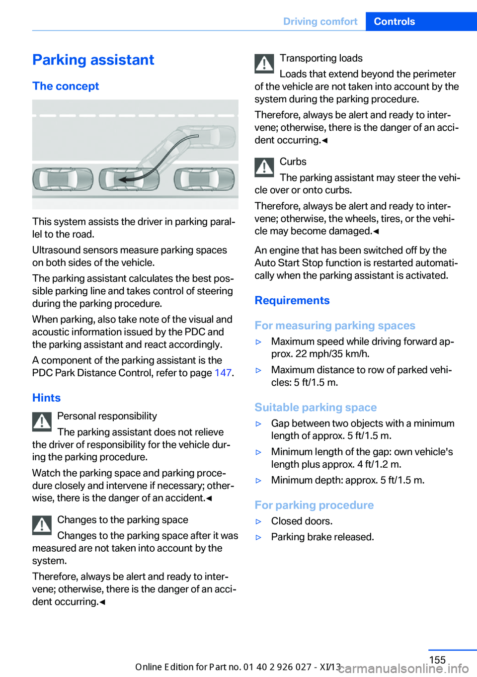
This system assists the driver in parking paral‐
lel to the road.
Ultrasound sensors measure parking spaces
on both sides of the vehicle.
The parking assistant calculates the best pos‐
sible parking line and takes control of steering
during the parking procedure.
When parking, also take note of the visual and
acoustic information issued by the PDC and
the parking assistant and react accordingly.
A component of the parking assistant is the
PDC Park Distance Control, refer to page 147.
Hints Personal responsibility
The parking assistant does not relieve
the driver of responsibility for the vehicle dur‐
ing the parking procedure.
Watch the parking space and parking proce‐
dure closely and intervene if necessary; other‐
wise, there is the danger of an accident.◀
Changes to the parking space
Changes to the parking space after it was
measured are not taken into account by the
system.
Therefore, always be alert and ready to inter‐
vene; otherwise, there is the danger of an acci‐
dent occurring.◀
Transporting loads
Loads that extend beyond the perimeter
of the vehicle are not taken into account by the
system during the parking procedure.
Therefore, always be alert and ready to inter‐
vene; otherwise, there is the danger of an acci‐
dent occurring.◀
Curbs
The parking assistant may steer the vehi‐
cle over or onto curbs.
Therefore, always be alert and ready to inter‐
vene; otherwise, the wheels, tires, or the vehi‐
cle may become damaged.◀
An engine that has been switched off by the
Auto Start Stop function is restarted automati‐
cally when the parking assistant is activated.
Requirements
For measuring parking spaces▷Maximum speed while driving forward ap‐
prox. 22 mph/35 km/h.▷Maximum distance to row of parked vehi‐
cles: 5 ft/1.5 m.
Suitable parking space
▷Gap between two objects with a minimum
length of approx. 5 ft/1.5 m.▷Minimum length of the gap: own vehicle's
length plus approx. 4 ft/1.2 m.▷Minimum depth: approx. 5 ft/1.5 m.
For parking procedure
▷Closed doors.▷Parking brake released.Seite 155Driving comfortControls155
Online Edition for Part no. 01 40 2 909 928 - VI/13
Page 174 of 255
erases all programming of the buttons on
the interior rearview mirror.3.Hold the hand-held transmitter for the sys‐
tem to be controlled approx. 1 to 3 in/2.5 to
8 cm away from the buttons on the interior
rearview mirror. The required distance de‐
pends on the manual transmitter.4.Simultaneously press and hold the button
of the desired function on the hand-held
transmitter and the button to be program‐
med on the interior rearview mirror. The
LED on the interior rearview mirror will be‐
gin flashing slowly.5.Release both buttons as soon as the LED
flashes more rapidly. When the LED is
flashing faster, this indicates that the but‐
ton on the interior rearview mirror has been
programmed.
If the LED does not flash faster after at
least 60 seconds, change the distance be‐
tween the interior rearview mirror and the
hand-held transmitter and repeat the step.
Several more attempts at different distan‐
ces may be necessary. Wait at least
15 seconds between attempts.
Canada: if programming with the hand-
held transmitter was interrupted, hold
down the interior rearview mirror button
and repeatedly press and release the
hand-held transmitter button for 2 sec‐
onds.6.To program other functions on other but‐
tons, repeat steps 3 to 5.
The systems can be controlled using the inte‐
rior rearview mirror buttons.
Special feature of the alternating-
code wireless system
If you are unable to operate the system after
repeated programming, please check if the
system to be controlled features an alternat‐
ing-code system.
Read the system's operating manual, or press
the programmed button on the interior rear‐
view mirror longer. If the LED on the interior
rearview mirror starts flashing rapidly and then
stays lit constantly for 2 seconds, the system
features an alternating-code system. Flashing
and continuous illumination of the LED will re‐
peat for approximately 20 seconds.
For systems with an alternating-code system,
the integrated universal remote control and the
system also have to be synchronized.
Please read the operating manual of the sys‐
tem being set up for information on how to
synchronize the system.
Synchronizing is easier with the aid of a sec‐
ond person.
To synchronize:1.Park the vehicle within range of the re‐
mote-controlled system.2.Program the relevant button on the interior
rearview mirror as described.3.Locate and press the synchronizing button
on the system being programmed. You
have approx. 30 seconds for the next step.4.Hold down the programmed button on the
interior rearview mirror for approximately
3 seconds and then release it. If necessary,
repeat this work step up to three times in
order to finish synchronization. Once syn‐
chronization is complete, the programmed
function will be carried out.
Reprogramming individual buttons
1.Switch on the ignition.2.Press and hold the interior rearview mirror
button to be programmed.3.As soon as the interior rearview mirror LED
starts flashing slowly, hold the hand-held
transmitter for the system to be controlled
approx. 1 to 3 in/2.5 to 8 cm away from the
buttons on the interior rearview mirror. The
required distance depends on the manual
transmitter.Seite 170ControlsInterior equipment170
Online Edition for Part no. 01 40 2 909 928 - VI/13
Page 175 of 255
4.Likewise, press and hold the button of the
desired function on the hand-held trans‐
mitter.5.Release both buttons as soon as the inte‐
rior rearview mirror LED flashes more rap‐
idly. When the LED is flashing faster, this
indicates that the button on the interior
rearview mirror has been programmed.
The system can then be controlled by the
button on the interior rearview mirror.
If the LED does not flash faster after at
least 60 seconds, change the distance and
repeat the step. Several more attempts at
different distances may be necessary. Wait
at least 15 seconds between attempts.
Canada: if programming with the hand-
held transmitter was interrupted, hold
down the interior rearview mirror button
and repeatedly press and release the
hand-held transmitter button for 2 sec‐
onds.
Controls
Before operation
Before operating a system using the
integrated universal remote control, ensure
that there are no people, animals, or objects
within the range of movement of the remote- controlled system; otherwise, there is a risk of
injury or damage.
Also follow the safety instructions of the hand-
held transmitter.◀
The system, such as the garage door, can be
operated using the button on the interior rear‐
view mirror while the engine is running or when
the ignition is started. To do this, hold down
the button within receiving range of the system
until the function is activated. The interior rear‐ view mirror LED stays lit while the wireless sig‐
nal is being transmitted.
Deleting stored functions Press and hold the left and right button on the
interior rearview mirror simultaneously for ap‐
proximately 20 seconds until the LED flashes
rapidly. All stored functions are deleted. The
functions cannot be deleted individually.
Ashtray/cigarette lighter Front
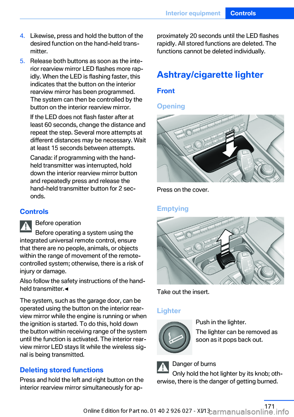
Opening
Press on the cover.
Emptying
Take out the insert. Lighter Push in the lighter.
The lighter can be removed as
soon as it pops back out.
Danger of burns
Only hold the hot lighter by its knob; oth‐
erwise, there is the danger of getting burned.
Seite 171Interior equipmentControls171
Online Edition for Part no. 01 40 2 909 928 - VI/13
Page 179 of 255
of injury due to unexpected movement of the
seat backrest.◀
Folding down the cargo partition Danger of pinching
Before folding down the trunk partition,
ensure that the area of movement of the parti‐
tion is clear. In particular, ensure that no one is
located in the area of movement and that no
one reaches into the area of movement of the
trunk partition when the middle section is
folded down. Otherwise, injury or damage may
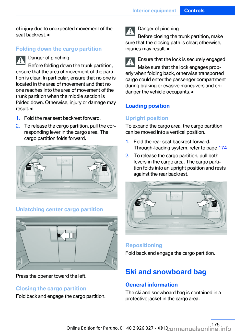
result.◀1.Fold the rear seat backrest forward.2.To release the cargo partition, pull the cor‐
responding lever in the cargo area. The
cargo partition folds forward.
Unlatching center cargo partition
Press the opener toward the left.
Closing the cargo partition Fold back and engage the cargo partition.
Danger of pinching
Before closing the trunk partition, make
sure that the closing path is clear; otherwise,
injuries may result.◀
Ensure that the lock is securely engaged
Make sure that the lock engages prop‐
erly when folding back, otherwise transported
cargo could enter the passenger compartment
during braking or evasive maneuvers and en‐
danger the vehicle occupants.◀
Loading position
Upright position
To expand the cargo area, the cargo partition
can be moved into a vertical position.1.Fold the rear seat backrest forward.
Through-loading system, refer to page 1742.To release the cargo partition, pull both
levers in the cargo area. The cargo parti‐
tion folds into an upright position and rests
against the rear backrest.
Repositioning
Fold back and engage the cargo partition.
Ski and snowboard bagGeneral information
The ski and snowboard bag is contained in a
protective jacket in the cargo area.
Seite 175Interior equipmentControls175
Online Edition for Part no. 01 40 2 909 928 - VI/13
Page 203 of 255
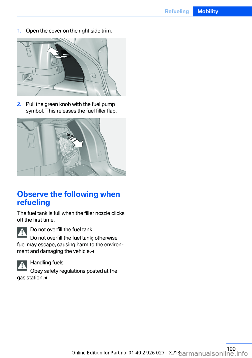
1.Open the cover on the right side trim.2.Pull the green knob with the fuel pump
symbol. This releases the fuel filler flap.
Observe the following when
refueling
The fuel tank is full when the filler nozzle clicks
off the first time.
Do not overfill the fuel tank
Do not overfill the fuel tank; otherwise
fuel may escape, causing harm to the environ‐
ment and damaging the vehicle.◀
Handling fuels
Obey safety regulations posted at the
gas station.◀
Seite 199RefuelingMobility199
Online Edition for Part no. 01 40 2 909 928 - VI/13
Page 207 of 255
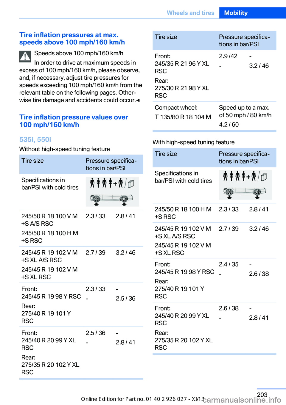
Tire inflation pressures at max.
speeds above 100 mph/160 km/h
Speeds above 100 mph/160 km/h
In order to drive at maximum speeds in
excess of 100 mph/160 km/h, please observe,
and, if necessary, adjust tire pressures for
speeds exceeding 100 mph/160 km/h from the
relevant table on the following pages. Other‐
wise tire damage and accidents could occur.◀
Tire inflation pressure values over
100 mph/160 km/h
535i, 550i
Without high-speed tuning feature
Tire sizePressure specifica‐
tions in bar/PSI
Specifications in
bar/PSI with cold tires
245/50 R 18 100 V M
+S A/S RSC
245/50 R 18 100 H M
+S RSC
2.3 / 332.8 / 41245/45 R 19 102 V M
+S XL A/S RSC
245/45 R 19 102 V M
+S XL RSC
2.7 / 393.2 / 46Front:
245/45 R 19 98 Y RSC
Rear:
275/40 R 19 101 Y
RSC
2.3 / 33
-
-
2.5 / 36
Front:
245/40 R 20 99 Y XL
RSC
Rear:
275/35 R 20 102 Y XL
RSC
2.5 / 36
-
-
2.8 / 41
Tire sizePressure specifica‐
tions in bar/PSI
Front:
245/35 R 21 96 Y XL
RSC
Rear:
275/30 R 21 98 Y XL
RSC
2.9 /42
-
-
3.2 / 46
Compact wheel:
T 135/80 R 18 104 M
Speed up to a max.
of 50 mph / 80 km/h
4.2 / 60
With high-speed tuning feature
Tire sizePressure specifica‐
tions in bar/PSI
Specifications in
bar/PSI with cold tires
245/50 R 18 100 H M
+S RSC
2.3 / 332.8 / 41245/45 R 19 102 V M
+S XL A/S RSC
2.7 / 393.2 / 46Front:
245/45 R 19 98 Y RSC
Rear:
275/40 R 19 101 Y
RSC
2.4 / 35
-
-
2.6 / 38
Front:
245/40 R 20 99 Y XL
RSC
Rear:
275/35 R 20 102 Y XL
RSC
2.6 / 38
-
-
2.8 / 41
Seite 203Wheels and tiresMobility203
Online Edition for Part no. 01 40 2 909 928 - VI/13
245/45 R 19 102 V M
+S XL RSC
Page 216 of 255
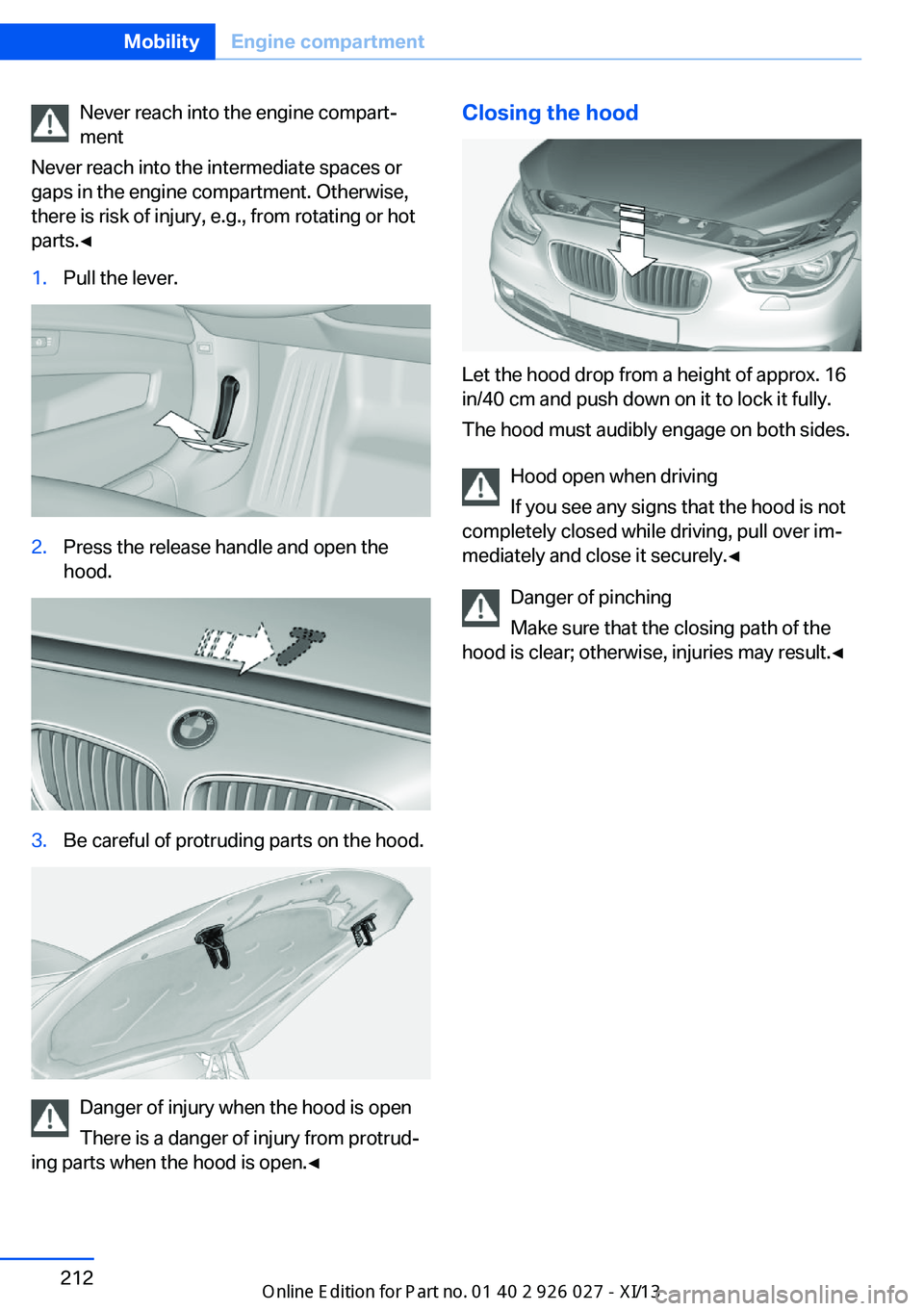
Never reach into the engine compart‐
ment
Never reach into the intermediate spaces or
gaps in the engine compartment. Otherwise,
there is risk of injury, e.g., from rotating or hot
parts.◀1.Pull the lever.2.Press the release handle and open the
hood.3.Be careful of protruding parts on the hood.
Danger of injury when the hood is open
There is a danger of injury from protrud‐
ing parts when the hood is open.◀
Closing the hood
Let the hood drop from a height of approx. 16
in/40 cm and push down on it to lock it fully.
The hood must audibly engage on both sides.
Hood open when driving
If you see any signs that the hood is not
completely closed while driving, pull over im‐
mediately and close it securely.◀
Danger of pinching
Make sure that the closing path of the
hood is clear; otherwise, injuries may result.◀
Seite 212MobilityEngine compartment212
Online Edition for Part no. 01 40 2 909 928 - VI/13
Page 230 of 255
if it can be established, are transmitted to
the BMW Response Center.▷If the LED is flashing, but the BMW Re‐
sponse Center can no longer be heard via
the speaker, you can nevertheless still be
heard for the BMW Response Center.
Initiating an Emergency Request
automatically
Under certain conditions, an Emergency Re‐
quest is automatically initiated immediately af‐
ter a severe accident. Automatic Collision Noti‐
fication is not affected by pressing the SOS
button.
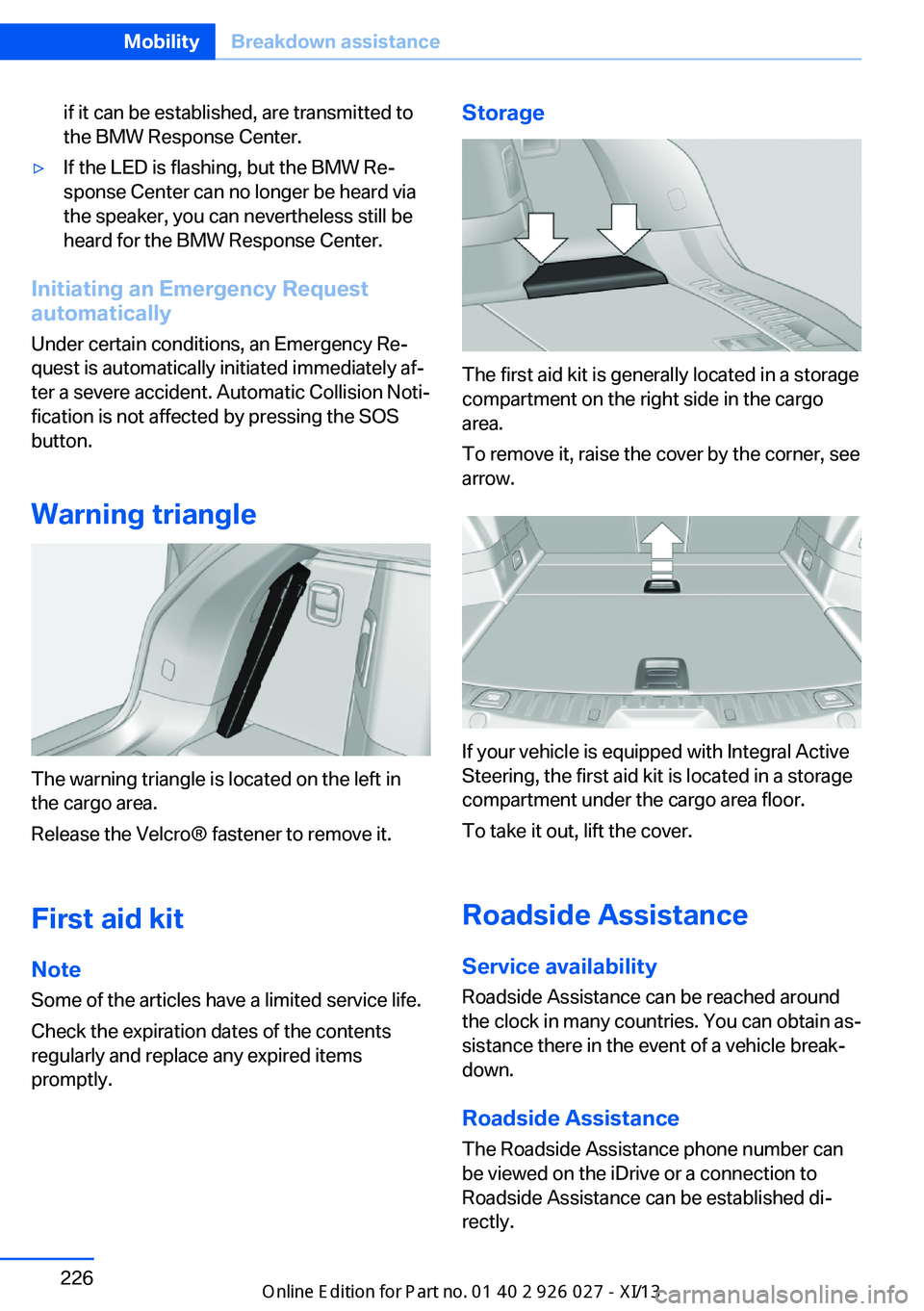
Warning triangle
The warning triangle is located on the left in
the cargo area.
Release the Velcro® fastener to remove it.
First aid kit NoteSome of the articles have a limited service life.
Check the expiration dates of the contents
regularly and replace any expired items
promptly.
Storage
The first aid kit is generally located in a storage
compartment on the right side in the cargo
area.
To remove it, raise the cover by the corner, see
arrow.
If your vehicle is equipped with Integral Active
Steering, the first aid kit is located in a storage
compartment under the cargo area floor.
To take it out, lift the cover.
Roadside Assistance
Service availability Roadside Assistance can be reached around
the clock in many countries. You can obtain as‐
sistance there in the event of a vehicle break‐
down.
Roadside Assistance The Roadside Assistance phone number can
be viewed on the iDrive or a connection to
Roadside Assistance can be established di‐
rectly.
Seite 226MobilityBreakdown assistance226
Online Edition for Part no. 01 40 2 909 928 - VI/13
Page 246 of 255
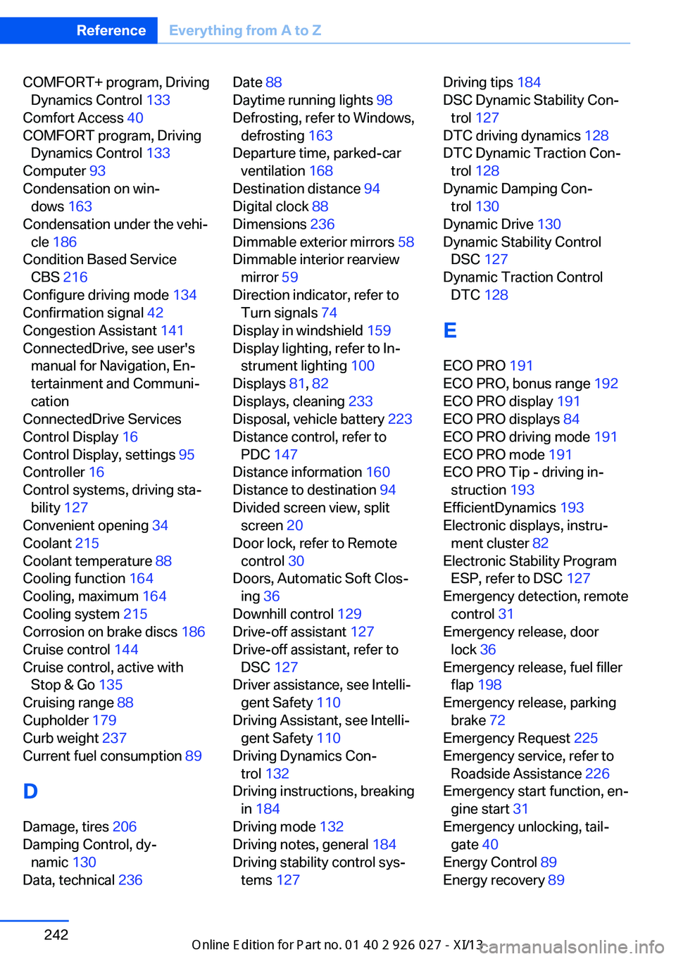
COMFORT+ program, DrivingDynamics Control 133
Comfort Access 40
COMFORT program, Driving Dynamics Control 133
Computer 93
Condensation on win‐ dows 163
Condensation under the vehi‐ cle 186
Condition Based Service CBS 216
Configure driving mode 134
Confirmation signal 42
Congestion Assistant 141
ConnectedDrive, see user's manual for Navigation, En‐
tertainment and Communi‐
cation
ConnectedDrive Services
Control Display 16
Control Display, settings 95
Controller 16
Control systems, driving sta‐ bility 127
Convenient opening 34
Coolant 215
Coolant temperature 88
Cooling function 164
Cooling, maximum 164
Cooling system 215
Corrosion on brake discs 186
Cruise control 144
Cruise control, active with Stop & Go 135
Cruising range 88
Cupholder 179
Curb weight 237
Current fuel consumption 89
D
Damage, tires 206
Damping Control, dy‐ namic 130
Data, technical 236 Date 88
Daytime running lights 98
Defrosting, refer to Windows, defrosting 163
Departure time, parked-car ventilation 168
Destination distance 94
Digital clock 88
Dimensions 236
Dimmable exterior mirrors 58
Dimmable interior rearview mirror 59
Direction indicator, refer to Turn signals 74
Display in windshield 159
Display lighting, refer to In‐ strument lighting 100
Displays 81, 82
Displays, cleaning 233
Disposal, vehicle battery 223
Distance control, refer to PDC 147
Distance information 160
Distance to destination 94
Divided screen view, split screen 20
Door lock, refer to Remote control 30
Doors, Automatic Soft Clos‐ ing 36
Downhill control 129
Drive-off assistant 127
Drive-off assistant, refer to DSC 127
Driver assistance, see Intelli‐ gent Safety 110
Driving Assistant, see Intelli‐ gent Safety 110
Driving Dynamics Con‐ trol 132
Driving instructions, breaking in 184
Driving mode 132
Driving notes, general 184
Driving stability control sys‐ tems 127 Driving tips 184
DSC Dynamic Stability Con‐ trol 127
DTC driving dynamics 128
DTC Dynamic Traction Con‐ trol 128
Dynamic Damping Con‐ trol 130
Dynamic Drive 130
Dynamic Stability Control DSC 127
Dynamic Traction Control DTC 128
E
ECO PRO 191
ECO PRO, bonus range 192
ECO PRO display 191
ECO PRO displays 84
ECO PRO driving mode 191
ECO PRO mode 191
ECO PRO Tip - driving in‐ struction 193
EfficientDynamics 193
Electronic displays, instru‐ ment cluster 82
Electronic Stability Program ESP, refer to DSC 127
Emergency detection, remote control 31
Emergency release, door lock 36
Emergency release, fuel filler flap 198
Emergency release, parking brake 72
Emergency Request 225
Emergency service, refer to Roadside Assistance 226
Emergency start function, en‐ gine start 31
Emergency unlocking, tail‐ gate 40
Energy Control 89
Energy recovery 89 Seite 242ReferenceEverything from A to Z242
Online Edition for Part no. 01 40 2 909 928 - VI/13