navigation system BMW 535I XDRIVE GT 2011 F07 User Guide
[x] Cancel search | Manufacturer: BMW, Model Year: 2011, Model line: 535I XDRIVE GT, Model: BMW 535I XDRIVE GT 2011 F07Pages: 297, PDF Size: 8.59 MB
Page 67 of 297
Before leaving the car with the engine running,
set
the parking brake and place the transmission
in position P or neutral to prevent the car from
moving.◀
Frequent starting in quick succession
Avoid repeated futile attempts at starting
the car and avoid starting the car frequently in
quick succession. Otherwise, the fuel is not
burned or is inadequately burned, and there is
the danger of overheating and damaging the
catalytic converter.◀
Do not wait for the engine to warm up while the
vehicle remains stationary. Start driving at mod‐
erate engine speeds.
Starting the engine
Press on the brake pedal and
press the Start/Stop button.
The engine is cranked until it
starts.
Engine stop
General information Take the remote control with you
Take the remote control with you when
leaving the vehicle so that children, for example,
cannot operate the windows and injure them‐
selves.◀
Set the parking brake and further secure
the vehicle as required
Set the parking brake firmly when parking; oth‐
erwise, the vehicle could roll. On steep upward
and downward inclines, further secure the vehi‐
cle, for example, by turning the steering wheel in
the direction of the curb. ◀
Before driving into a car wash
In order for the vehicle to be able to roll into a car
wash, heed the information regarding Washing
in automatic car washes, refer to page 269. Switching off the engine
1.
Engage transmission position P with the ve‐
hicle stopped.
2. Press the Start/Stop button.
The engine is switched off.
The radio ready state is switched on.
3. Set the parking brake.
Parking brake
The concept
The
parking brake is used to prevent the vehicle
from rolling when it is parked.
▷ Engine switched off: the parking brake acts
on the rear wheels.
▷ Engine running: the parking brake acts on
the disc brakes of the front and rear wheels
via the hydraulic brake system.
The parking brake can be set manually or auto‐
matically:
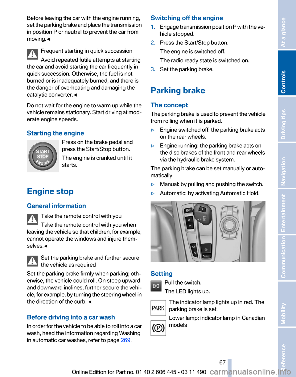
▷ Manual: by pulling and pushing the switch.
▷ Automatic: by activating Automatic Hold. Setting
Pull the switch.
The LED lights up.
The indicator lamp lights up in red. The
parking brake is set.
Lower lamp: indicator lamp in Canadian
models Seite 67
67Online Edition for Part no. 01 40 2 606 445 - 03 11 490
Reference Mobility Communication Entertainment Navigation Driving tips
Controls At a glance
Page 69 of 297
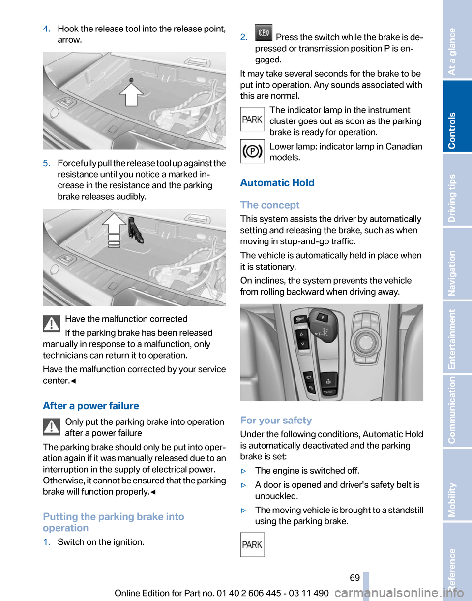
4.
Hook the release tool into the release point,
arrow. 5.
Forcefully pull the release tool up against the
resistance until you notice a marked in‐
crease in the resistance and the parking
brake releases audibly. Have the malfunction corrected
If the parking brake has been released
manually in response to a malfunction, only
technicians can return it to operation.
Have
the malfunction corrected by your service
center.◀
After a power failure
Only put the parking brake into operation
after a power failure
The parking brake should only be put into oper‐
ation again if it was manually released due to an
interruption in the supply of electrical power.
Otherwise, it cannot be ensured that the parking
brake will function properly.◀
Putting the parking brake into
operation
1. Switch on the ignition. 2. Press the switch while the brake is de‐
pressed or transmission position P is en‐
gaged.
It may take several seconds for the brake to be
put into operation. Any sounds associated with
this are normal. The indicator lamp in the instrument
cluster goes out as soon as the parking
brake is ready for operation.
Lower lamp: indicator lamp in Canadian
models.
Automatic Hold
The concept
This system assists the driver by automatically
setting and releasing the brake, such as when
moving in stop-and-go traffic.
The vehicle is automatically held in place when
it is stationary.
On inclines, the system prevents the vehicle
from rolling backward when driving away. For your safety
Under
the following conditions, Automatic Hold
is automatically deactivated and the parking
brake is set:
▷ The engine is switched off.
▷ A door is opened and driver's safety belt is
unbuckled.
▷ The moving vehicle is brought to a standstill
using the parking brake. Seite 69
69Online Edition for Part no. 01 40 2 606 445 - 03 11 490
Reference Mobility Communication Entertainment Navigation Driving tips
Controls At a glance
Page 71 of 297
Turn signal, high beams,
headlamp flasher
Turn signal
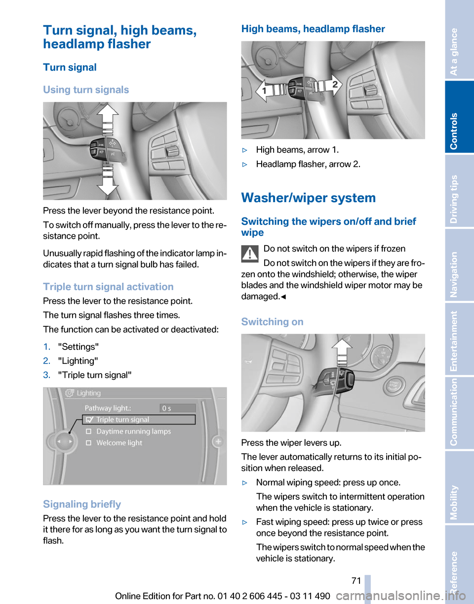
Using turn signals
Press the lever beyond the resistance point.
To
switch off manually, press the lever to the re‐
sistance point.
Unusually rapid flashing of the indicator lamp in‐
dicates that a turn signal bulb has failed.
Triple turn signal activation
Press the lever to the resistance point.
The turn signal flashes three times.
The function can be activated or deactivated:
1. "Settings"
2. "Lighting"
3. "Triple turn signal" Signaling briefly
Press the lever to the resistance point and hold
it
there for as long as you want the turn signal to
flash. High beams, headlamp flasher
▷
High beams, arrow 1.
▷ Headlamp flasher, arrow 2.
Washer/wiper system
Switching the wipers on/off and brief
wipe Do not switch on the wipers if frozen
Do
not switch on the wipers if they are fro‐
zen onto the windshield; otherwise, the wiper
blades and the windshield wiper motor may be
damaged.◀
Switching on Press the wiper levers up.
The lever automatically returns to its initial po‐
sition when released.
▷
Normal wiping speed: press up once.
The wipers switch to intermittent operation
when the vehicle is stationary.
▷ Fast wiping speed: press up twice or press
once beyond the resistance point.
The
wipers switch to normal speed when the
vehicle is stationary. Seite 71
71Online Edition for Part no. 01 40 2 606 445 - 03 11 490
Reference Mobility Communication Entertainment Navigation Driving tips
Controls At a glance
Page 73 of 297
Windshield washer nozzles
The washer jets are automatically heated*
whenever the ignition is switched on.
Fold-out position of the wipers
Required when changing the wiper blades or
under frosty conditions, for example.
1.
Switch off the ignition.
2. Under frosty conditions, ensure that the
wiper blades are not frozen onto the wind‐
shield.
3. Press the wiper lever up beyond the point of
resistance
and hold it for approx. 3 seconds,
until the wiper remains in a nearly vertical
position.
After the wipers are folded back down, the wiper
system must be reactivated.
Fold the wipers back down
Before switching the ignition on, fold the
wipers
back down to the windshield; otherwise,
the wipers may become damaged when they are
switched on.◀
1. Switch on the ignition.
2. Press the wiper levers down. The wipers
move
to their resting position and are ready
for operation.
Washer fluid
General information Antifreeze for washer fluid
Antifreeze is flammable. Therefore, keep
it away from sources of ignition.
Only
keep it in the closed original container and
inaccessible to children.
Follow the instructions on the container.◀ Washer fluid reservoir
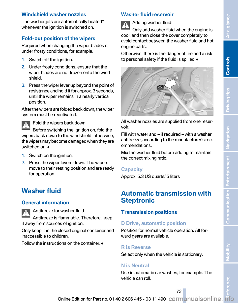
Adding washer fluid
Only add washer fluid when the engine is
cool, and then close the cover completely to
avoid
contact between the washer fluid and hot
engine parts.
Otherwise, there is the danger of fire and a risk
to personal safety if the fluid is spilled.◀ All washer nozzles are supplied from one reser‐
voir.
Fill with water and – if required – with a washer
antifreeze,
according to the manufacturer's rec‐
ommendations.
Mix the washer fluid before adding to maintain
the correct mixing ratio.
Capacity
Approx. 5.3 US quarts/ 5 liters
Automatic transmission with
Steptronic
Transmission positions
D Drive, automatic position
Position for normal vehicle operation. All for‐
ward gears are available.
R is Reverse
Select only when the vehicle is stationary.
N is Neutral
Use in automatic car washes, for example. The
vehicle can roll. Seite 73
73Online Edition for Part no. 01 40 2 606 445 - 03 11 490
Reference Mobility Communication Entertainment Navigation Driving tips
Controls At a glance
Page 79 of 297
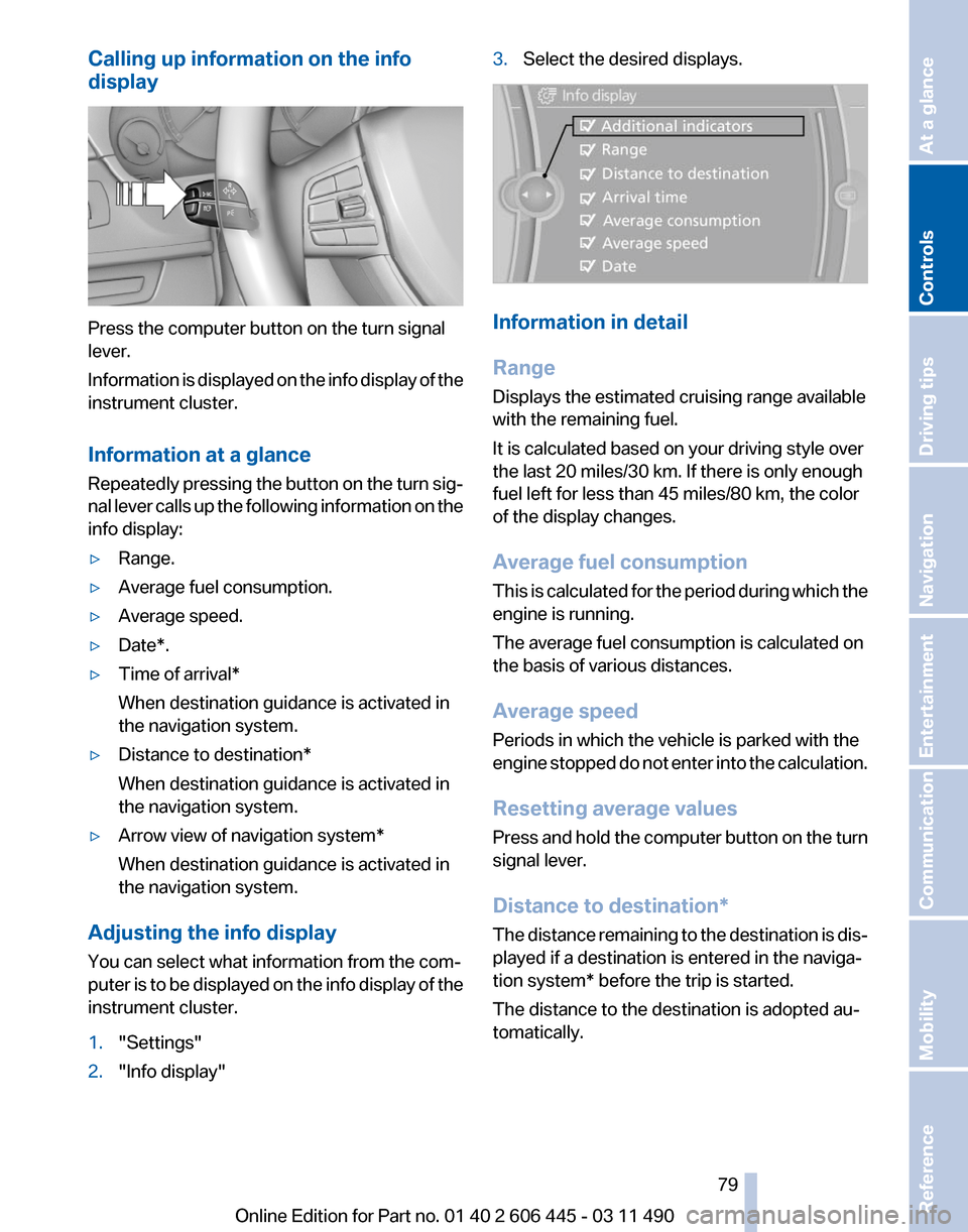
Calling up information on the info
display
Press the computer button on the turn signal
lever.
Information
is displayed on the info display of the
instrument cluster.
Information at a glance
Repeatedly pressing the button on the turn sig‐
nal lever calls up the following information on the
info display:
▷ Range.
▷ Average fuel consumption.
▷ Average speed.
▷ Date*.
▷ Time of arrival*
When destination guidance is activated in
the navigation system.
▷ Distance to destination*
When destination guidance is activated in
the navigation system.
▷ Arrow view of navigation system*
When destination guidance is activated in
the navigation system.
Adjusting the info display
You can select what information from the com‐
puter
is to be displayed on the info display of the
instrument cluster.
1. "Settings"
2. "Info display" 3.
Select the desired displays. Information in detail
Range
Displays the estimated cruising range available
with the remaining fuel.
It is calculated based on your driving style over
the last 20 miles/30 km. If there is only enough
fuel left for less than 45 miles/80 km, the color
of the display changes.
Average fuel consumption
This
is calculated for the period during which the
engine is running.
The average fuel consumption is calculated on
the basis of various distances.
Average speed
Periods in which the vehicle is parked with the
engine stopped do not enter into the calculation.
Resetting average values
Press and hold the computer button on the turn
signal lever.
Distance to destination*
The distance remaining to the destination is dis‐
played if a destination is entered in the naviga‐
tion system* before the trip is started.
The distance to the destination is adopted au‐
tomatically.
Seite 79
79Online Edition for Part no. 01 40 2 606 445 - 03 11 490
Reference Mobility Communication Entertainment Navigation Driving tips
Controls At a glance
Page 80 of 297
Time of arrival*
The estimated time of arrival is
displayed if a destination is en‐
tered in the navigation system
*
before the trip is started.
The time must be correctly set.
Speed limit
Display of a speed limit which, when reached,
should cause a warning to be issued.
Renewed warning if the vehicle speed drops be‐
low the set speed limit once by at least 3 mph/
5 km/h.
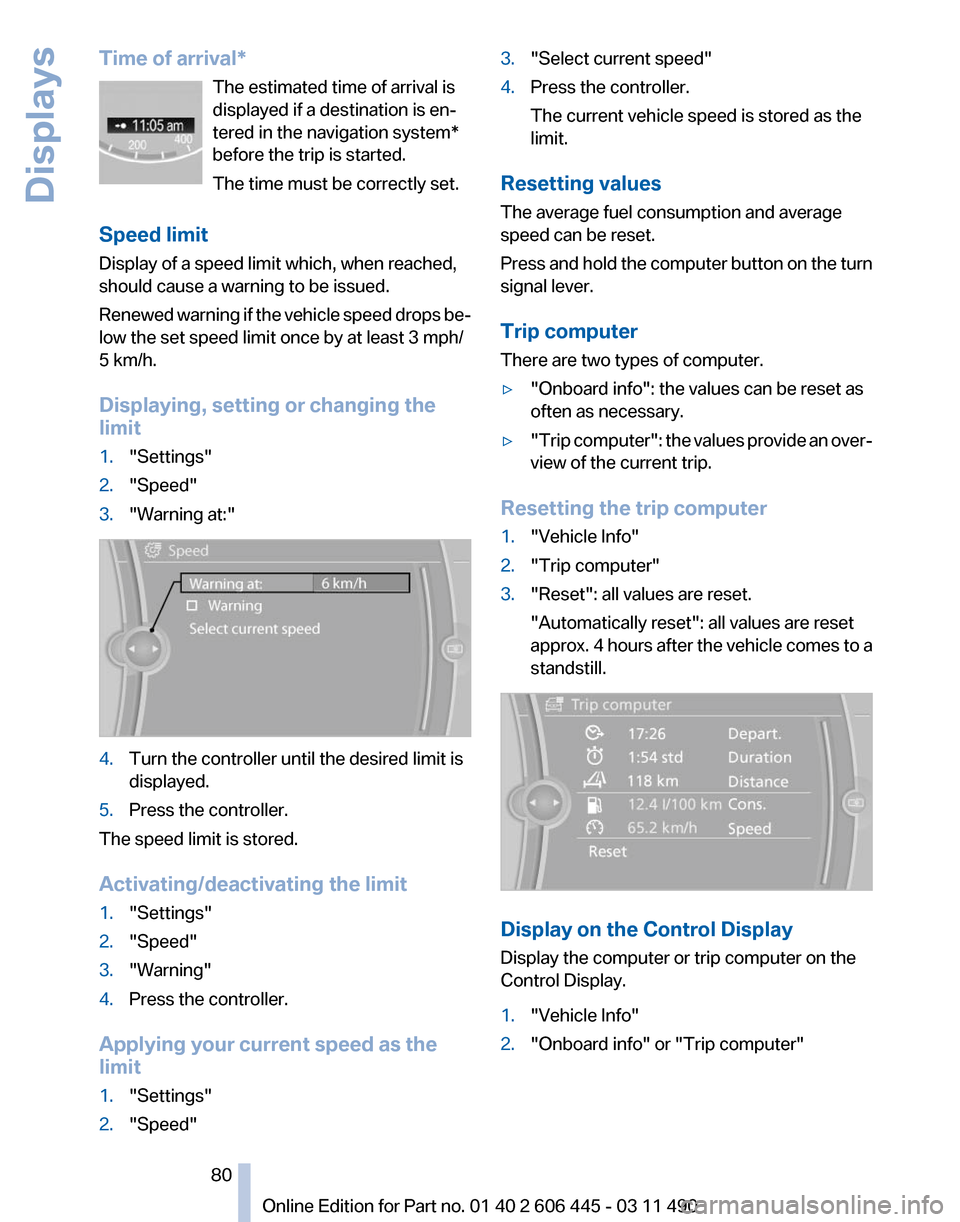
Displaying, setting or changing the
limit
1. "Settings"
2. "Speed"
3. "Warning at:" 4.
Turn the controller until the desired limit is
displayed.
5. Press the controller.
The speed limit is stored.
Activating/deactivating the limit
1. "Settings"
2. "Speed"
3. "Warning"
4. Press the controller.
Applying your current speed as the
limit
1. "Settings"
2. "Speed" 3.
"Select current speed"
4. Press the controller.
The current vehicle speed is stored as the
limit.
Resetting values
The average fuel consumption and average
speed can be reset.
Press
and hold the computer button on the turn
signal lever.
Trip computer
There are two types of computer.
▷ "Onboard info": the values can be reset as
often as necessary.
▷ "Trip
computer": the values provide an over‐
view of the current trip.
Resetting the trip computer
1. "Vehicle Info"
2. "Trip computer"
3. "Reset": all values are reset.
"Automatically reset": all values are reset
approx.
4 hours after the vehicle comes to a
standstill. Display on the Control Display
Display the computer or trip computer on the
Control Display.
1.
"Vehicle Info"
2. "Onboard info" or "Trip computer"
Seite 80
80 Online Edition for Part no. 01 40 2 606 445 - 03 11 490
Displays
Page 83 of 297
Detailed information on service
requirements
More information on the scope of service re‐
quired can be displayed on the Control Display.
1.
"Vehicle Info"
2. "Vehicle status"
3. "Service required"
Required maintenance procedures and le‐
gally mandated inspections are displayed.
4. Select an entry to call up detailed informa‐
tion.
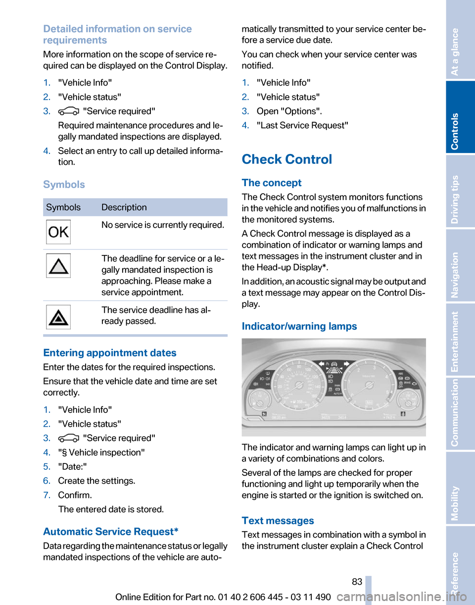
Symbols Symbols Description
No service is currently required.
The deadline for service or a le‐
gally mandated inspection is
approaching. Please make a
service appointment.
The service deadline has al‐
ready passed.
Entering appointment dates
Enter the dates for the required inspections.
Ensure that the vehicle date and time are set
correctly.
1.
"Vehicle Info"
2. "Vehicle status"
3. "Service required"
4. "§ Vehicle inspection"
5. "Date:"
6. Create the settings.
7. Confirm.
The entered date is stored.
Automatic Service Request*
Data regarding the maintenance status or legally
mandated inspections of the vehicle are auto‐ matically transmitted to your service center be‐
fore a service due date.
You can check when your service center was
notified.
1.
"Vehicle Info"
2. "Vehicle status"
3. Open "Options".
4. "Last Service Request"
Check Control
The concept
The Check Control system monitors functions
in
the vehicle and notifies you of malfunctions in
the monitored systems.
A Check Control message is displayed as a
combination of indicator or warning lamps and
text messages in the instrument cluster and in
the Head-up Display*.
In addition, an acoustic signal may be output and
a text message may appear on the Control Dis‐
play.
Indicator/warning lamps The indicator and warning lamps can light up in
a variety of combinations and colors.
Several of the lamps are checked for proper
functioning and light up temporarily when the
engine is started or the ignition is switched on.
Text messages
Text
messages in combination with a symbol in
the instrument cluster explain a Check Control
Seite 83
83Online Edition for Part no. 01 40 2 606 445 - 03 11 490
Reference Mobility Communication Entertainment Navigation Driving tips
Controls At a glance
Page 87 of 297
To avoid blinding oncoming traffic, the adaptive
light control directs light towards the front pas‐
senger side when the vehicle is at a standstill.
When
driving in reverse, only the turning lamp is
active.
Self-leveling headlights
The self-leveling headlights feature adapts the
light distribution to the contours of the road.
The light distribution is lowered on hilltops to
avoid blinding oncoming traffic and tilted in de‐
pressions to increase visibility.
Malfunction
A Check Control message is displayed.
Adaptive light control is malfunctioning or has
failed. Have the system checked as soon as pos‐
sible.
High-beam Assistant*
The concept
When the low beams are switched on, this sys‐
tem automatically switches the high beams on
and off. The procedure is controlled by a sensor
on the front of the interior rearview mirror. The
assistant ensures that the high beams are
switched on whenever the traffic situation al‐
lows. The driver can intervene at any time and
switch the high beams on and off as usual.
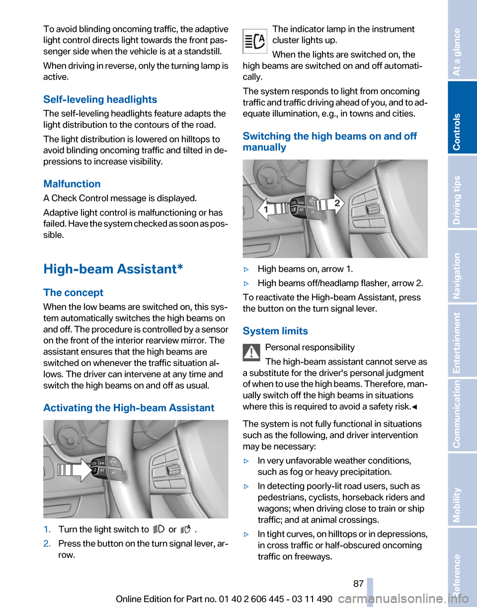
Activating the High-beam Assistant 1.
Turn the light switch to or .
2. Press the button on the turn signal lever, ar‐
row. The indicator lamp in the instrument
cluster lights up.
When the lights are switched on, the
high beams are switched on and off automati‐
cally.
The system responds to light from oncoming
traffic
and traffic driving ahead of you, and to ad‐
equate illumination, e.g., in towns and cities.
Switching the high beams on and off
manually ▷
High beams on, arrow 1.
▷ High beams off/headlamp flasher, arrow 2.
To reactivate the High-beam Assistant, press
the button on the turn signal lever.
System limits
Personal responsibility
The high-beam assistant cannot serve as
a substitute for the driver's personal judgment
of
when to use the high beams. Therefore, man‐
ually switch off the high beams in situations
where this is required to avoid a safety risk.◀
The system is not fully functional in situations
such as the following, and driver intervention
may be necessary:
▷ In very unfavorable weather conditions,
such as fog or heavy precipitation.
▷ In detecting poorly-lit road users, such as
pedestrians, cyclists, horseback riders and
wagons; when driving close to train or ship
traffic; and at animal crossings.
▷ In tight curves, on hilltops or in depressions,
in cross traffic or half-obscured oncoming
traffic on freeways. Seite 87
87Online Edition for Part no. 01 40 2 606 445 - 03 11 490
Reference Mobility Communication Entertainment Navigation Driving tips
Controls At a glance
Page 90 of 297
▷
Keep the dashboard and window on the
front
passenger side clear, i.e., do not cover
with adhesive labels or coverings, and do not
attach holders such as for navigation instru‐
ments and mobile phones.
▷ Make sure that the front passenger is sitting
correctly, i.e., keeps his or her feet and legs
in the footwell; otherwise, leg injuries can
occur if the front airbag is triggered.
▷ Do not place slip covers, seat cushions or
other objects on the front passenger seat
that are not approved specifically for seats
with integrated side airbags.
▷ Do not hang pieces of clothing, such as jack‐
ets, over the backrests.
▷ Make sure that occupants keep their heads
away from the side airbag and do not rest
against the head airbag; otherwise, injuries
can occur if the airbags are triggered.
▷ Do not remove the airbag restraint system.
▷ Do not remove the steering wheel.
▷ Do not apply adhesive materials to the air‐
bag cover panels, cover them or modify
them in any way.
▷ Never modify either the individual compo‐
nents
or the wiring in the airbag system. This
also applies to steering wheel covers, the
dashboard, the seats, the roof pillars and the
sides of the headliner.◀
Even when all instructions are followed closely,
injury from contact with the airbags cannot be
ruled out in certain situations.
The ignition and inflation noise may lead to
short-term
and, in most cases, temporary hear‐
ing impairment in sensitive individuals.
In the case of a malfunction, deactivation
and after triggering of the airbags
Do not touch the individual components imme‐
diately after the system has been triggered; oth‐
erwise, there is the danger of burns.
Only have the airbags checked, repaired or dis‐
mantled and the airbag generator scrapped by
your service center or a workshop that has the
necessary authorization for handling explosives. Non-professional attempts to service the sys‐
tem
could lead to failure in an emergency or un‐
desired triggering of the airbag, either of which
could result in injury.◀
Warnings and information on the airbags are
also found on the sun visors.
Functional readiness of the airbag
system
When the ignition is switch on, the warn‐
ing lamp in the instrument cluster lights
up briefly and thereby indicates the op‐
erational readiness of the entire airbag system
and the belt tensioner.
Airbag system malfunctioning
▷ In radio ready state, the warning lamp does
not come on.
▷ The warning lamp lights up continuously.
When there is a malfunction, have the air‐
bag system checked immediately
When there is a malfunction, have the airbag
system checked immediately; otherwise, there
is
a risk that the system does not function as ex‐
pected in the event of an accident despite cor‐
responding severity of the accident.◀
Automatic deactivation of the front
passenger airbags
The system determines whether the front pas‐
senger seat is occupied by measuring the re‐
sistance of the human body.
The front, knee, and side airbag on the front
passenger side are activated or deactivated ac‐
cordingly.
Leave feet in the footwell
Make sure that the front passenger keeps
his or her feet in the footwell; otherwise, the front
passenger airbags may not function properly.◀ Seite 90
90 Online Edition for Part no. 01 40 2 606 445 - 03 11 490
Safety
Page 91 of 297
Child restraint fixing system in the front
passenger seat
Before
transporting a child on the front passen‐
ger seat, see the safety notes and instructions
under Children on the front passenger seat.◀
Malfunction of the automatic
deactivation system
When transporting older children and adults, the
front passenger airbags may be deactivated in
certain sitting positions. In this case, the indica‐
tor lamp for the front passenger airbags lights
up.
In this case, change the sitting position so that
the front passenger airbags are activated and
the indicator lamp goes out.
If it is not possible to activate the airbags, have
the person sit in the rear.
To make sure that the occupied seat cushion
can be evaluated correctly
▷ Do not attach covers, cushions, ball mats or
other items to the front passenger seat un‐
less they are specifically recommended by
the manufacturer of your vehicle.
▷ Do not place any objects on the front pas‐
senger seat.
▷ Do not place objects under the seat that
could press against the seat from below.
Indicator lamp for the front passenger
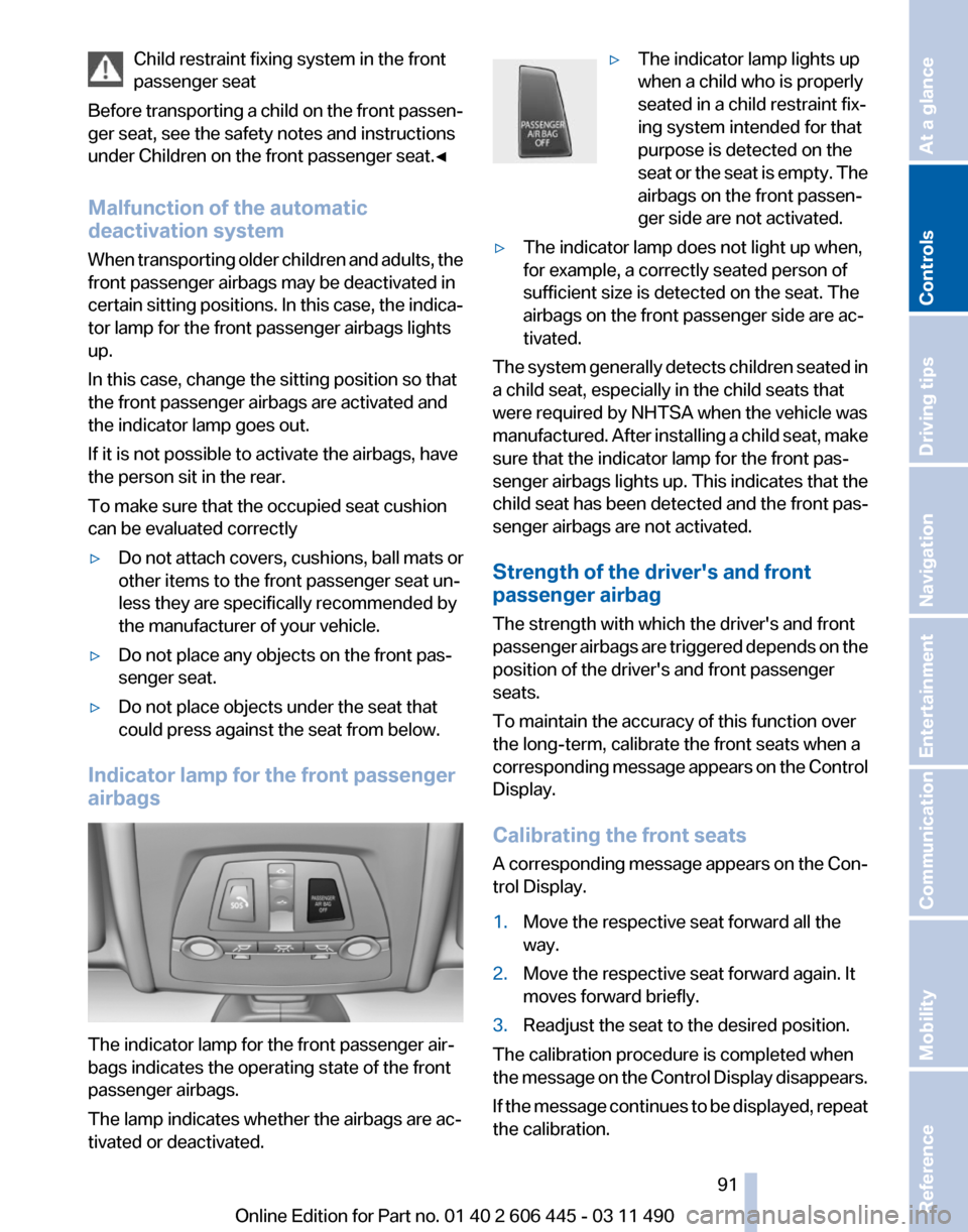
airbags The indicator lamp for the front passenger air‐
bags indicates the operating state of the front
passenger airbags.
The lamp indicates whether the airbags are ac‐
tivated or deactivated. ▷
The indicator lamp lights up
when a child who is properly
seated in a child restraint fix‐
ing system intended for that
purpose is detected on the
seat
or the seat is empty. The
airbags on the front passen‐
ger side are not activated.
▷ The indicator lamp does not light up when,
for example, a correctly seated person of
sufficient size is detected on the seat. The
airbags on the front passenger side are ac‐
tivated.
The system generally detects children seated in
a child seat, especially in the child seats that
were required by NHTSA when the vehicle was
manufactured.
After installing a child seat, make
sure that the indicator lamp for the front pas‐
senger airbags lights up. This indicates that the
child seat has been detected and the front pas‐
senger airbags are not activated.
Strength of the driver's and front
passenger airbag
The strength with which the driver's and front
passenger airbags are triggered depends on the
position of the driver's and front passenger
seats.
To maintain the accuracy of this function over
the long-term, calibrate the front seats when a
corresponding message appears on the Control
Display.
Calibrating the front seats
A corresponding message appears on the Con‐
trol Display.
1. Move the respective seat forward all the
way.
2. Move the respective seat forward again. It
moves forward briefly.
3. Readjust the seat to the desired position.
The calibration procedure is completed when
the
message on the Control Display disappears.
If the message continues to be displayed, repeat
the calibration. Seite 91
91Online Edition for Part no. 01 40 2 606 445 - 03 11 490
Reference Mobility Communication Entertainment Navigation Driving tips
Controls At a glance