navigation system BMW 535I XDRIVE GT 2011 F07 Workshop Manual
[x] Cancel search | Manufacturer: BMW, Model Year: 2011, Model line: 535I XDRIVE GT, Model: BMW 535I XDRIVE GT 2011 F07Pages: 297, PDF Size: 8.59 MB
Page 202 of 297
Remote control
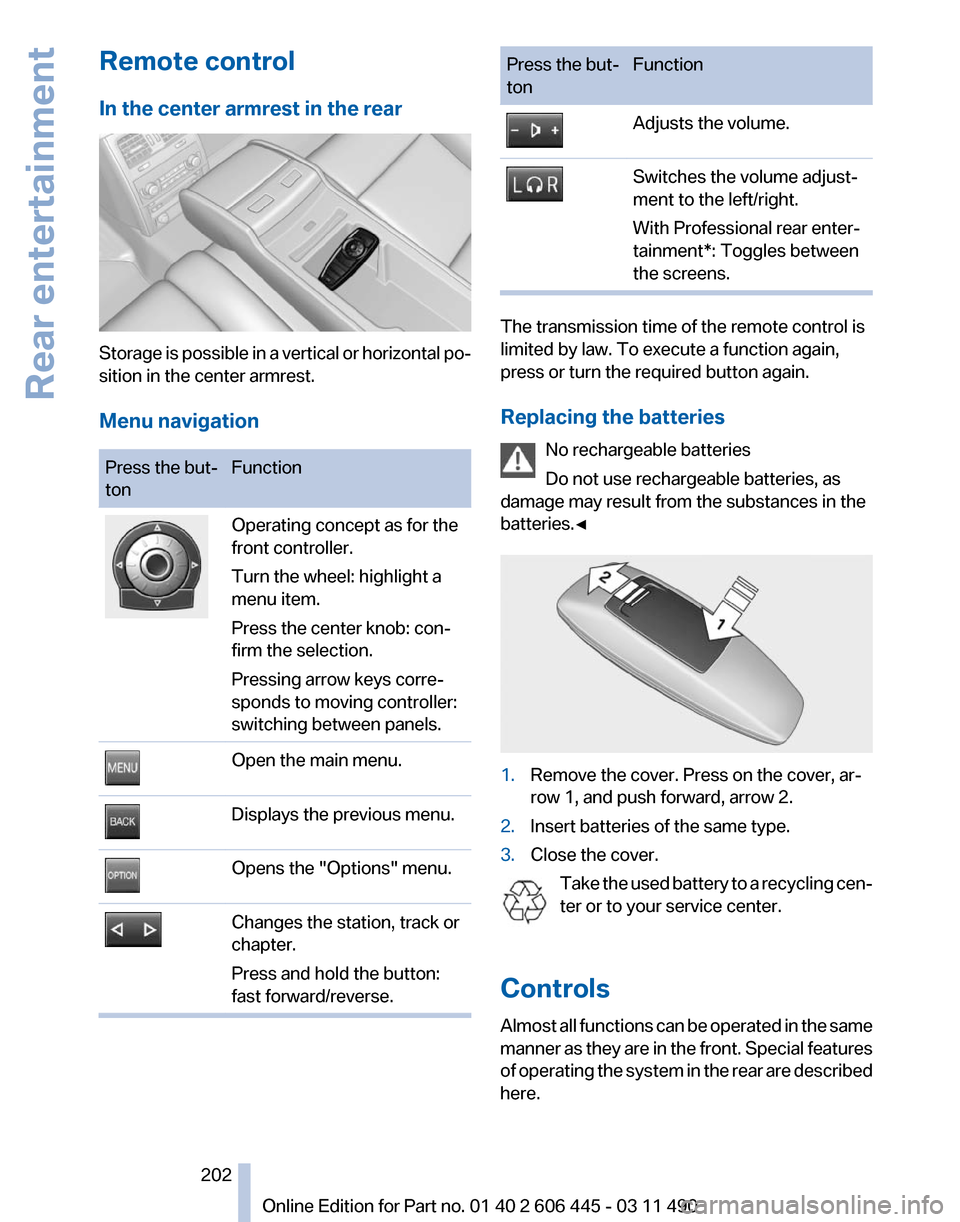
In the center armrest in the rear
Storage is possible in a vertical or horizontal po‐
sition in the center armrest.
Menu navigation
Press the but‐
ton
Function Operating concept as for the
front controller.
Turn the wheel: highlight a
menu item.
Press the center knob: con‐
firm the selection.
Pressing arrow keys corre‐
sponds to moving controller:
switching between panels.
Open the main menu.
Displays the previous menu.
Opens the "Options" menu.
Changes the station, track or
chapter.
Press and hold the button:
fast forward/reverse. Press the but‐
ton
Function Adjusts the volume.
Switches the volume adjust‐
ment to the left/right.
With Professional rear enter‐
tainment*: Toggles between
the screens.
The transmission time of the remote control is
limited by law. To execute a function again,
press or turn the required button again.
Replacing the batteries
No rechargeable batteries
Do not use rechargeable batteries, as
damage may result from the substances in the
batteries.◀ 1.
Remove the cover. Press on the cover, ar‐
row 1, and push forward, arrow 2.
2. Insert batteries of the same type.
3. Close the cover.
Take the used battery to a recycling cen‐
ter or to your service center.
Controls
Almost
all functions can be operated in the same
manner as they are in the front. Special features
of operating the system in the rear are described
here. Seite 202
202 Online Edition for Part no. 01 40 2 606 445 - 03 11 490
Rear entertainment
Page 217 of 297
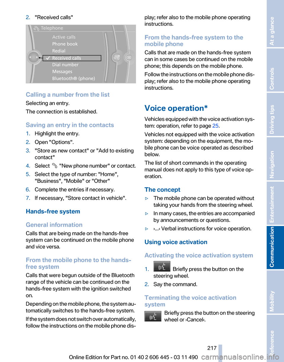
2.
"Received calls" Calling a number from the list
Selecting an entry.
The connection is established.
Saving an entry in the contacts
1.
Highlight the entry.
2. Open "Options".
3. "Store as new contact" or "Add to existing
contact"
4. Select "New phone number" or contact.
5. Select the type of number: "Home",
"Business", "Mobile" or "Other"
6. Complete the entries if necessary.
7. If necessary, "Store contact in vehicle".
Hands-free system
General information
Calls that are being made on the hands-free
system can be continued on the mobile phone
and vice versa.
From the mobile phone to the hands-
free system
Calls that were begun outside of the Bluetooth
range of the vehicle can be continued on the
hands-free system with the ignition switched
on.
Depending
on the mobile phone, the system au‐
tomatically switches to the hands-free system.
If the system does not switch over automatically,
follow the instructions on the mobile phone dis‐ play; refer also to the mobile phone operating
instructions.
From the hands-free system to the
mobile phone
Calls that are made on the hands-free system
can in some cases be continued on the mobile
phone; this depends on the mobile phone.
Follow
the instructions on the mobile phone dis‐
play; refer also to the mobile phone operating
instructions.
Voice operation*
Vehicles equipped with the voice activation sys‐
tem: operation, refer to page 25.
Vehicles not equipped with the voice activation
system: depending on the equipment, the mo‐
bile phone can be voice operated as described
below.
The list of short commands in the operating
manual does not apply to this type of voice op‐
eration.
The concept
▷ The mobile phone can be operated without
taking your hands from the steering wheel.
▷ In many cases, the entries are accompanied
by announcements or questions.
▷ ›...‹ Verbal instructions for voice operation.
Using voice activation
Activating the voice activation system
1. Briefly press the button on the
steering wheel.
2. Say the command.
Terminating the voice activation
system Briefly
press the button on the steering
wheel or ›Cancel‹. Seite 217
217Online Edition for Part no. 01 40 2 606 445 - 03 11 490
Reference Mobility
Communication Entertainment Navigation Driving tips Controls At a glance
Page 219 of 297
Adjusting the volume
Turn the knob during an announcement.
▷
The volume remains constant even if the
volume of other audio sources is changed.
▷ The volume is stored for the remote control
currently in use.
Notes
Do not use the voice operation to initiate an
Emergency
Request. In stressful situations, the
voice and vocal pitch can change. This can un‐
necessarily delay the establishment of a tele‐
phone connection.
Instead, use the SOS button*, refer to
page 264, in the vicinity of the interior mirror.
Environmental conditions
▷ Say the commands, numbers, and letters
smoothly and with normal volume, empha‐
sis, and speed.
▷ Always say commands in the language of
the system. The language for the mobile
phone voice operation is preset and cannot
be changed in the Control Display.
▷ Keep the doors, windows, and glass sun‐
roof* closed to prevent noise interference.
▷ Avoid making other noise in the vehicle
while speaking.
Snap-in adapter*
Installation position
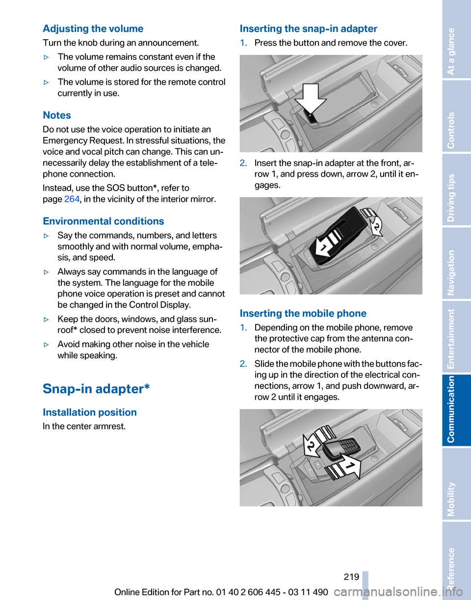
In the center armrest. Inserting the snap-in adapter
1.
Press the button and remove the cover. 2.
Insert the snap-in adapter at the front, ar‐
row 1, and press down, arrow 2, until it en‐
gages. Inserting the mobile phone
1.
Depending on the mobile phone, remove
the protective cap from the antenna con‐
nector of the mobile phone.
2. Slide the mobile phone with the buttons fac‐
ing up in the direction of the electrical con‐
nections, arrow 1, and push downward, ar‐
row 2 until it engages. Seite 219
219Online Edition for Part no. 01 40 2 606 445 - 03 11 490
Reference Mobility
Communication Entertainment Navigation Driving tips Controls At a glance
Page 223 of 297
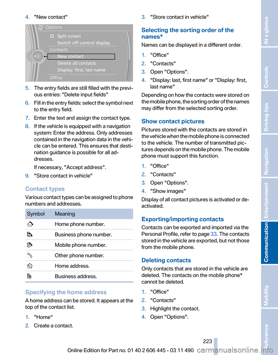
4.
"New contact" 5.
The entry fields are still filled with the previ‐
ous entries: "Delete input fields"
6. Fill in the entry fields: select the symbol next
to the entry field.
7. Enter the text and assign the contact type.
8. If the vehicle is equipped with a navigation
system: Enter the address. Only addresses
contained
in the navigation data in the vehi‐
cle can be entered. This ensures that desti‐
nation guidance is possible for all ad‐
dresses.
If necessary, "Accept address".
9. "Store contact in vehicle"
Contact types
Various
contact types can be assigned to phone
numbers and addresses. Symbol Meaning
Home phone number.
Business phone number.
Mobile phone number.
Other phone number.
Home address.
Business address.
Specifying the home address
A
home address can be stored. It appears at the
top of the contact list.
1. "Home"
2. Create a contact. 3.
"Store contact in vehicle"
Selecting the sorting order of the
names*
Names can be displayed in a different order.
1. "Office"
2. "Contacts"
3. Open "Options".
4. "Display: last, first name" or "Display: first,
last name"
Depending on how the contacts were stored on
the
mobile phone, the sorting order of the names
may differ from the selected sorting order.
Show contact pictures
Pictures stored with the contacts are stored in
the vehicle when the mobile phone is connected
to the vehicle. The number of transmitted pic‐
tures depends on the mobile phone. The mobile
phone must support this function.
1. "Office"
2. "Contacts"
3. Open "Options".
4. "Show images"
Display of all contact pictures is activated or de‐
activated.
Exporting/importing contacts
Contacts can be exported and imported via the
Personal Profile, refer to page 33. The contacts
stored
in the vehicle are exported, but not those
from the mobile phone.
Deleting contacts
Only contacts that are stored in the vehicle are
deleted. The contacts on the mobile phone*
cannot be deleted.
1. "Office"
2. "Contacts"
3. Highlight the contact.
4. Open "Options".
Seite 223
223Online Edition for Part no. 01 40 2 606 445 - 03 11 490
Reference Mobility
Communication Entertainment Navigation Driving tips Controls At a glance
Page 230 of 297
Contacts*
General information
Contacts
can be created and edited and the ad‐
dresses can be adopted as destinations for nav‐
igation.
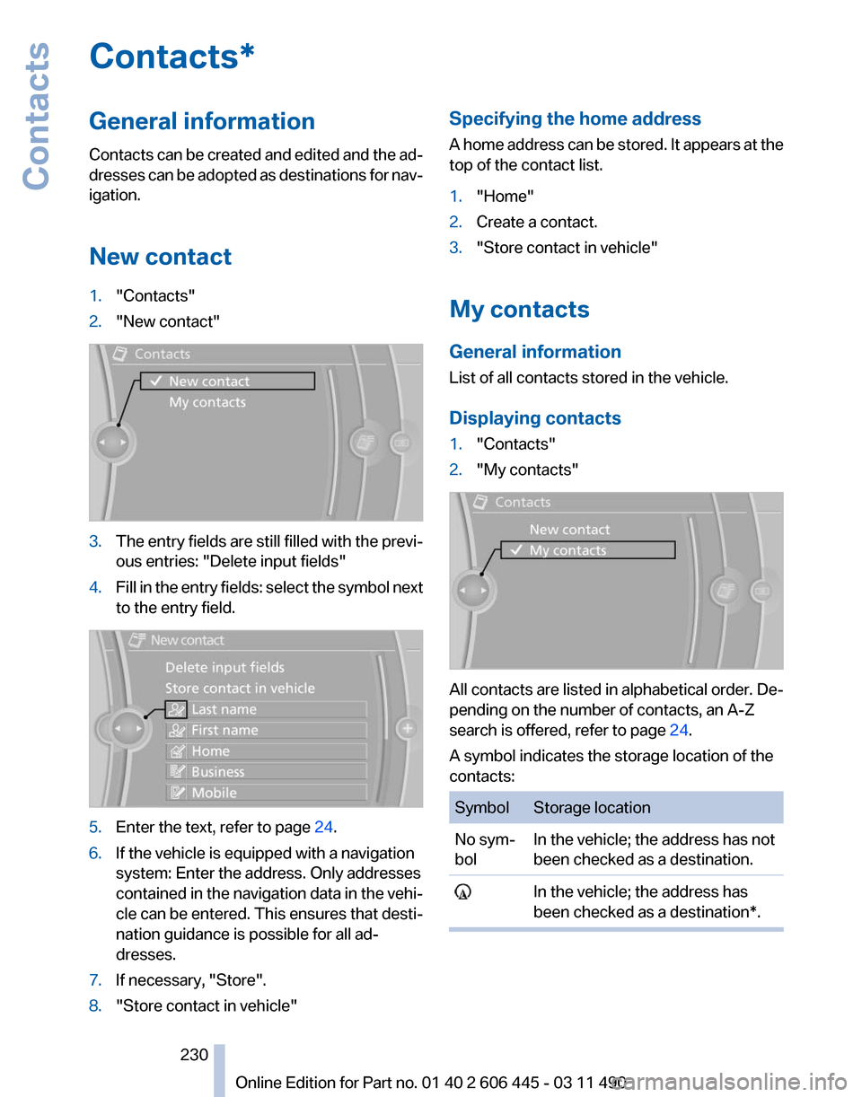
New contact
1. "Contacts"
2. "New contact" 3.
The entry fields are still filled with the previ‐
ous entries: "Delete input fields"
4. Fill in the entry fields: select the symbol next
to the entry field. 5.
Enter the text, refer to page 24.
6. If the vehicle is equipped with a navigation
system: Enter the address. Only addresses
contained
in the navigation data in the vehi‐
cle can be entered. This ensures that desti‐
nation guidance is possible for all ad‐
dresses.
7. If necessary, "Store".
8. "Store contact in vehicle" Specifying the home address
A
home address can be stored. It appears at the
top of the contact list.
1. "Home"
2. Create a contact.
3. "Store contact in vehicle"
My contacts
General information
List of all contacts stored in the vehicle.
Displaying contacts
1. "Contacts"
2. "My contacts" All contacts are listed in alphabetical order. De‐
pending on the number of contacts, an A-Z
search is offered, refer to page
24.
A symbol indicates the storage location of the
contacts: Symbol Storage location
No sym‐
bol
In the vehicle; the address has not
been checked as a destination. In the vehicle; the address has
been checked as a destination*. Seite 230
230 Online Edition for Part no. 01 40 2 606 445 - 03 11 490
Contacts
Page 257 of 297
This indicates that there is excessive
misfiring in the engine.
Reduce the vehicle speed and have
the system checked immediately;
otherwise, serious engine misfiring
within a brief period can seriously
damage emission control compo‐
nents,
in particular the catalytic con‐
verter.
Fuel cap The indicator lamp lights up.
If the fuel cap is not properly tightened,
the
OBD system may conclude that fuel
vapor is escaping. If the cap is then tightened,
the display should go out in a short time.
Data memory
Your vehicle records data relating to vehicle op‐
eration, faults and user settings. These data are
stored in the remote control and can be read out
with suitable devices, particularly when the ve‐
hicle is serviced. The data obtained in this way
provide valuable information for service proc‐
esses and repair or for optimizing and develop‐
ing vehicle functions further.
In addition, if you signed a service contract for
Assist, certain vehicle data can be sent directly
from the vehicle to facilitate the desired serv‐
ices. Seite 257
257Online Edition for Part no. 01 40 2 606 445 - 03 11 490
Reference
Mobility Communication Entertainment Navigation Driving tips Controls At a glance
Page 259 of 297
Do not touch the bulbs
Do not touch the glass of new bulbs with
your bare hands, as even minute amounts of
contamination will burn into the bulb's surface
and reduce its service life.
Use
a clean tissue, cloth or something similar, or
hold the bulb by its base.◀
Light-emitting diodes (LEDs)
Light-emitting diodes installed behind a cover
serve as the light source for controls, display el‐
ements and other equipment.
These light-emitting diodes, which are related
to conventional lasers, are officially designated
as Class 1 light-emitting diodes.
Do not remove the covers
Do not remove the covers, and never stare
into the unfiltered light for several hours; other‐
wise, irritation of the retina could result.◀
Headlamp glass
Condensation can form on the inside of the ex‐
ternal lamps in cool or humid weather. When the
light is switched on, the condensation evapo‐
rates after a short time. The headlamp glasses
do not need to be changed.
If there is a large amount of moisture, e.g., water
droplets form in the lamp, have it checked by
your service center.
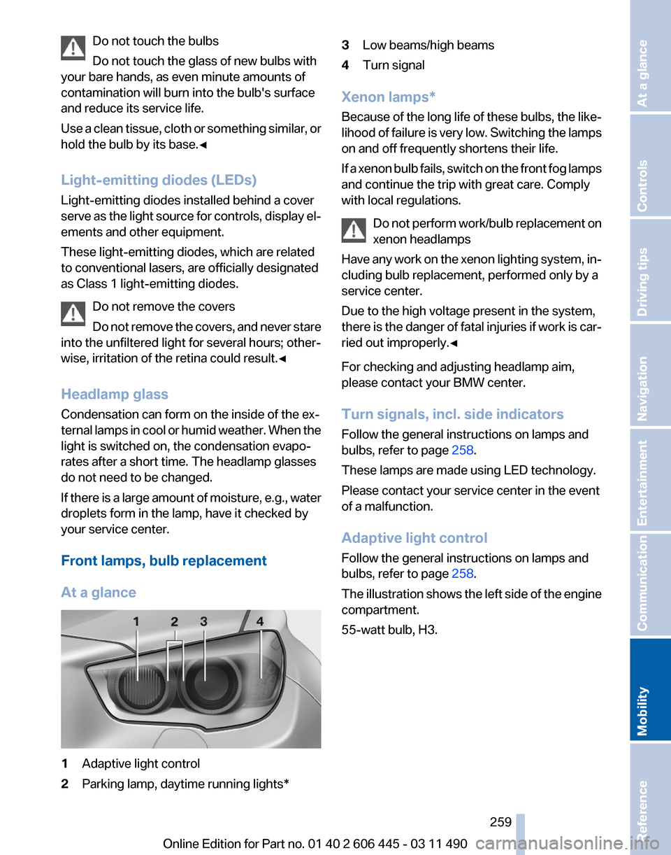
Front lamps, bulb replacement
At a glance 1
Adaptive light control
2 Parking lamp, daytime running lights* 3
Low beams/high beams
4 Turn signal
Xenon lamps*
Because
of the long life of these bulbs, the like‐
lihood of failure is very low. Switching the lamps
on and off frequently shortens their life.
If a xenon bulb fails, switch on the front fog lamps
and continue the trip with great care. Comply
with local regulations.
Do not perform work/bulb replacement on
xenon headlamps
Have any work on the xenon lighting system, in‐
cluding bulb replacement, performed only by a
service center.
Due to the high voltage present in the system,
there is the danger of fatal injuries if work is car‐
ried out improperly.◀
For checking and adjusting headlamp aim,
please contact your BMW center.
Turn signals, incl. side indicators
Follow the general instructions on lamps and
bulbs, refer to page 258.
These lamps are made using LED technology.
Please contact your service center in the event
of a malfunction.
Adaptive light control
Follow the general instructions on lamps and
bulbs, refer to page 258.
The illustration shows the left side of the engine
compartment.
55-watt bulb, H3. Seite 259
259Online Edition for Part no. 01 40 2 606 445 - 03 11 490
Reference
Mobility Communication Entertainment Navigation Driving tips Controls At a glance
Page 262 of 297
When using run-flat tires* or tire sealants, a tire
does
not need to be changed immediately in the
event of pressure loss due to a flat tire.
The tools for changing wheels are available as
accessories from your service center.
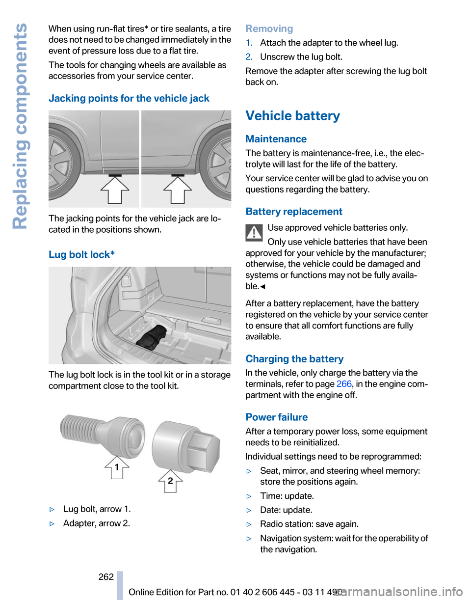
Jacking points for the vehicle jack The jacking points for the vehicle jack are lo‐
cated in the positions shown.
Lug bolt lock*
The lug bolt lock is in the tool kit or in a storage
compartment close to the tool kit.
▷
Lug bolt, arrow 1.
▷ Adapter, arrow 2. Removing
1.
Attach the adapter to the wheel lug.
2. Unscrew the lug bolt.
Remove the adapter after screwing the lug bolt
back on.
Vehicle battery
Maintenance
The battery is maintenance-free, i.e., the elec‐
trolyte will last for the life of the battery.
Your
service center will be glad to advise you on
questions regarding the battery.
Battery replacement
Use approved vehicle batteries only.
Only use vehicle batteries that have been
approved for your vehicle by the manufacturer;
otherwise, the vehicle could be damaged and
systems or functions may not be fully availa‐
ble.◀
After a battery replacement, have the battery
registered on the vehicle by your service center
to ensure that all comfort functions are fully
available.
Charging the battery
In the vehicle, only charge the battery via the
terminals, refer to page 266, in the engine com‐
partment with the engine off.
Power failure
After a temporary power loss, some equipment
needs to be reinitialized.
Individual settings need to be reprogrammed:
▷ Seat, mirror, and steering wheel memory:
store the positions again.
▷ Time: update.
▷ Date: update.
▷ Radio station: save again.
▷ Navigation system: wait for the operability of
the navigation. Seite 262
262 Online Edition for Part no. 01 40 2 606 445 - 03 11 490
Replacing components
Page 265 of 297
Assist Response Center may still be able to
hear you.
Initiating an Emergency Request
automatically
Under certain conditions, an Emergency Re‐
quest is automatically initiated immediately after
a severe accident. Automatic Collision Notifica‐
tion is not affected by pressing the SOS button.
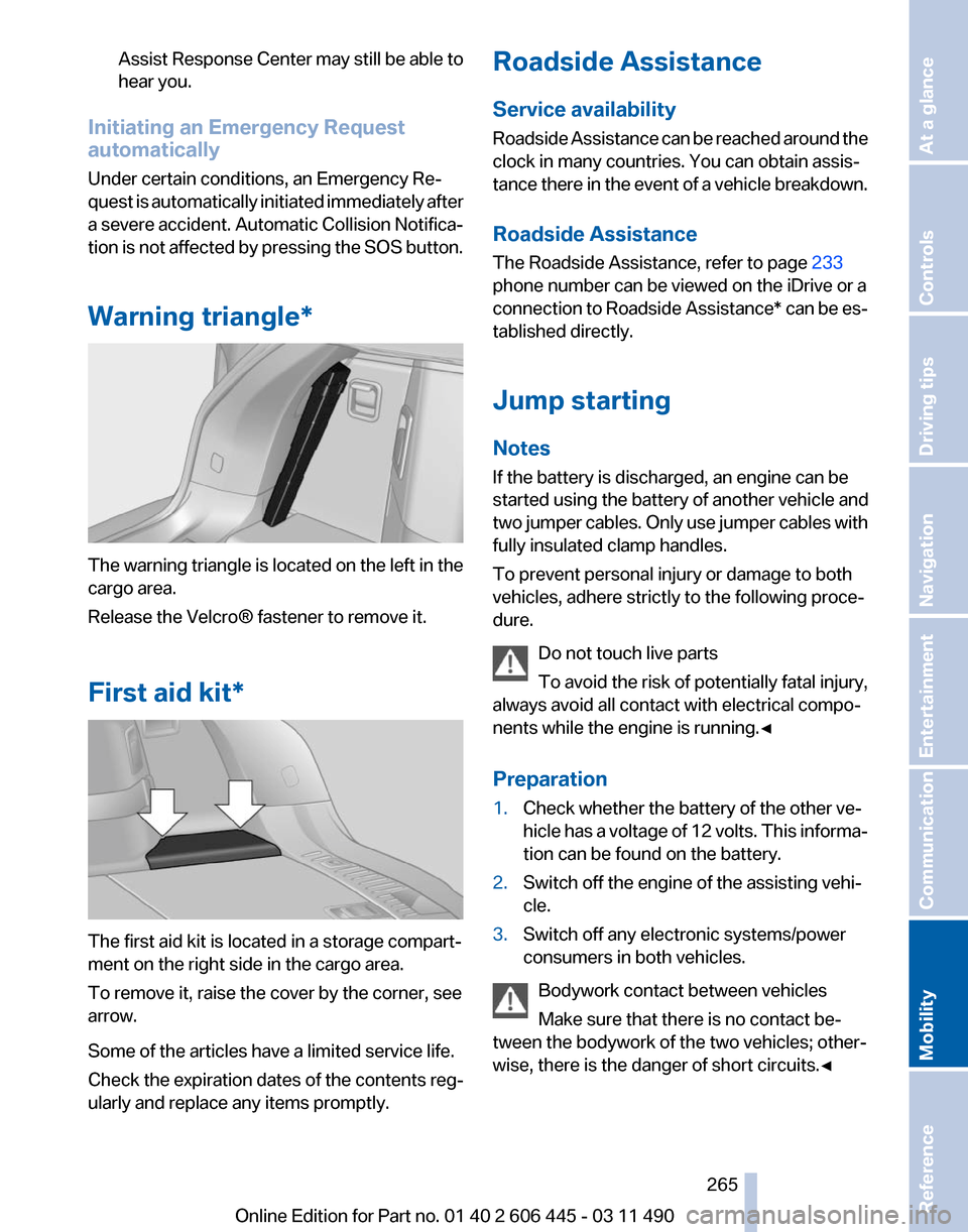
Warning triangle* The warning triangle is located on the left in the
cargo area.
Release the Velcro® fastener to remove it.
First aid kit*
The first aid kit is located in a storage compart‐
ment on the right side in the cargo area.
To remove it, raise the cover by the corner, see
arrow.
Some of the articles have a limited service life.
Check the expiration dates of the contents reg‐
ularly and replace any items promptly. Roadside Assistance
Service availability
Roadside Assistance can be reached around the
clock in many countries. You can obtain assis‐
tance there in the event of a vehicle breakdown.
Roadside Assistance
The Roadside Assistance, refer to page
233
phone number can be viewed on the iDrive or a
connection to Roadside Assistance* can be es‐
tablished directly.
Jump starting
Notes
If the battery is discharged, an engine can be
started using the battery of another vehicle and
two jumper cables. Only use jumper cables with
fully insulated clamp handles.
To prevent personal injury or damage to both
vehicles, adhere strictly to the following proce‐
dure.
Do not touch live parts
To avoid the risk of potentially fatal injury,
always avoid all contact with electrical compo‐
nents while the engine is running.◀
Preparation
1. Check whether the battery of the other ve‐
hicle has a voltage of 12 volts. This informa‐
tion can be found on the battery.
2. Switch off the engine of the assisting vehi‐
cle.
3. Switch off any electronic systems/power
consumers in both vehicles.
Bodywork contact between vehicles
Make sure that there is no contact be‐
tween the bodywork of the two vehicles; other‐
wise, there is the danger of short circuits.◀ Seite 265
265Online Edition for Part no. 01 40 2 606 445 - 03 11 490
Reference
Mobility Communication Entertainment Navigation Driving tips Controls At a glance
Page 267 of 297
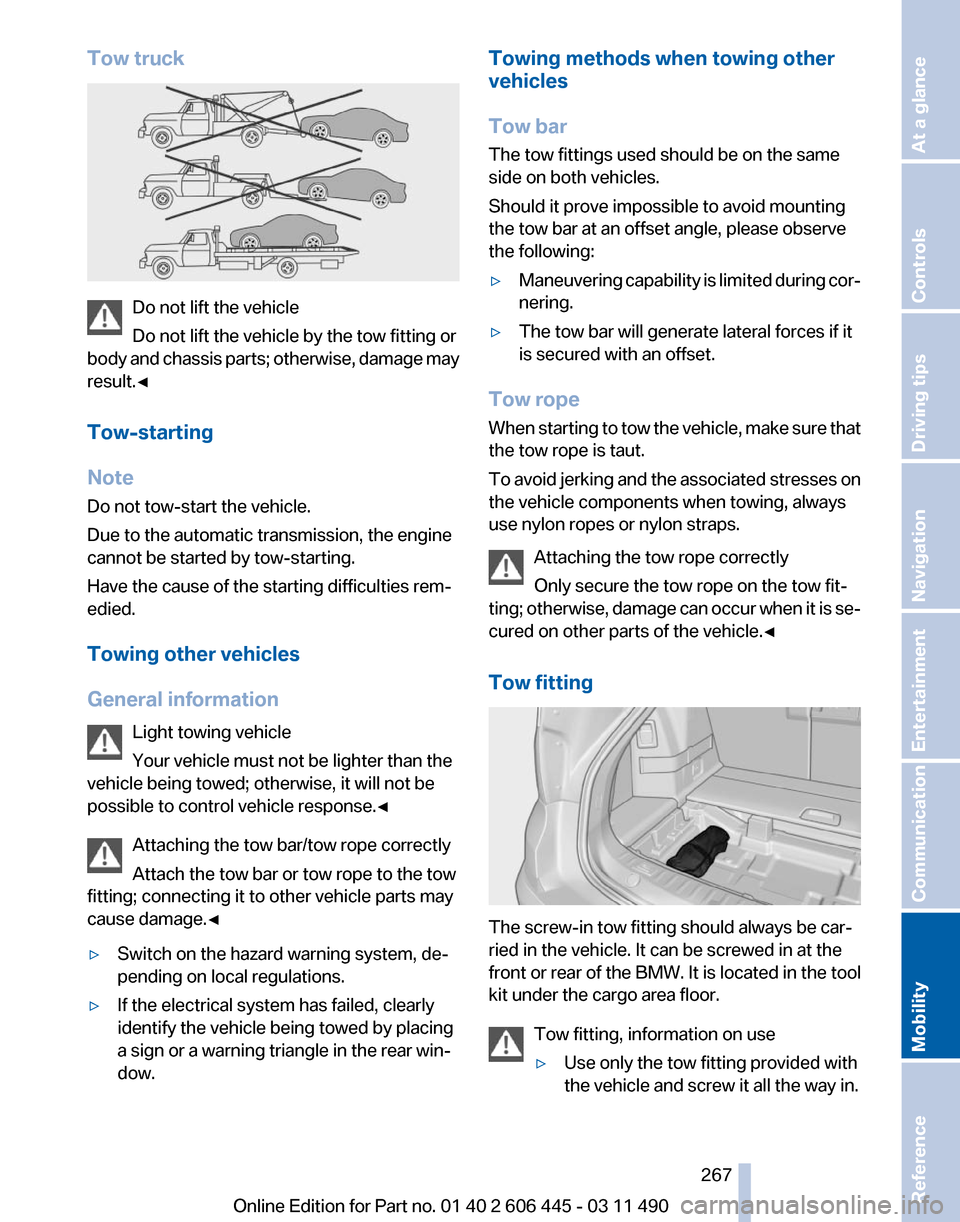
Tow truck
Do not lift the vehicle
Do not lift the vehicle by the tow fitting or
body
and chassis parts; otherwise, damage may
result.◀
Tow-starting
Note
Do not tow-start the vehicle.
Due to the automatic transmission, the engine
cannot be started by tow-starting.
Have the cause of the starting difficulties rem‐
edied.
Towing other vehicles
General information
Light towing vehicle
Your vehicle must not be lighter than the
vehicle being towed; otherwise, it will not be
possible to control vehicle response.◀
Attaching the tow bar/tow rope correctly
Attach the tow bar or tow rope to the tow
fitting; connecting it to other vehicle parts may
cause damage.◀
▷ Switch on the hazard warning system, de‐
pending on local regulations.
▷ If the electrical system has failed, clearly
identify the vehicle being towed by placing
a sign or a warning triangle in the rear win‐
dow. Towing methods when towing other
vehicles
Tow bar
The tow fittings used should be on the same
side on both vehicles.
Should it prove impossible to avoid mounting
the tow bar at an offset angle, please observe
the following:
▷
Maneuvering capability is limited during cor‐
nering.
▷ The tow bar will generate lateral forces if it
is secured with an offset.
Tow rope
When
starting to tow the vehicle, make sure that
the tow rope is taut.
To avoid jerking and the associated stresses on
the vehicle components when towing, always
use nylon ropes or nylon straps.
Attaching the tow rope correctly
Only secure the tow rope on the tow fit‐
ting; otherwise, damage can occur when it is se‐
cured on other parts of the vehicle.◀
Tow fitting The screw-in tow fitting should always be car‐
ried in the vehicle. It can be screwed in at the
front
or rear of the BMW. It is located in the tool
kit under the cargo area floor.
Tow fitting, information on use
▷Use only the tow fitting provided with
the vehicle and screw it all the way in. Seite 267
267Online Edition for Part no. 01 40 2 606 445 - 03 11 490
Reference
Mobility Communication Entertainment Navigation Driving tips Controls At a glance