BMW 540i 1998 E39 Workshop Manual
Manufacturer: BMW, Model Year: 1998, Model line: 540i, Model: BMW 540i 1998 E39Pages: 1002
Page 541 of 1002
Downloaded from www.Manualslib.com manuals search engine
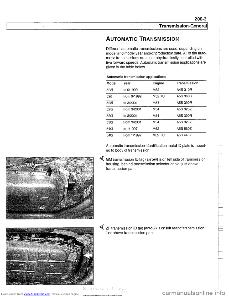
Different automatic transmissions are used, depending on
model and model year
and/orproduction date. All of the auto-
matic transmissions are electrohydraulically controlled with
five forward speeds. Automatic transmission applications are
given in the table below.
Automatic transmission applications Model Year Engine Transmission
526 from 911 999 M52 TU ASS 360R
5251 from 312001 M54 ASS 3252
5301 to 312001 M54 ASS 390R
530i from 312001 M54 ASS 3252
540i
from 111 997 M62 TU ASS 4402
Automatic transmission identification metal ID plate is mount-
ed to body of transmission.
4 GM transmission ID tag (arrow) is on left side of transmission
housing, behind transmission selector cable, just above
transmission pan.
< ZF transmission ID tag (arrow) is on left rear of transmission,
just above transmission pan.
Page 542 of 1002
Downloaded from www.Manualslib.com manuals search engine
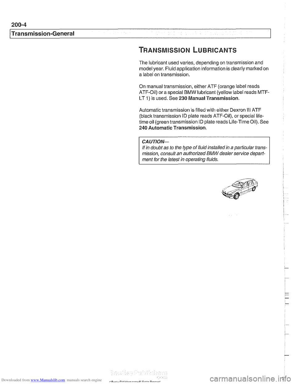
The lubricant used varies, depending on transmission and
model year. Fluid application information is clearly marked on
a label on transmission.
On manual transmission, either ATF (orange label reads
ATF-Oil) or a special BMW lubricant (yellow label reads MTF-
LT
I) is used. See 230 Manual Transmission.
Automatic transmission is filled with either Dexron
Ill ATF
(black transmission ID plate reads ATF-Oil), or special life-
time oil (green transmission ID plate reads Life-Time Oil). See
240 Automatic Transmission.
CAUTION--
If in doubt as to the type of fluid installed in a particular trans-
mission, consult an authorized
BMW dealer service depari-
ment for the latest in operating fluids.
Page 543 of 1002
Downloaded from www.Manualslib.com manuals search engine
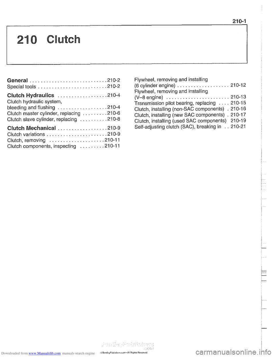
210 Clutch
........................... General .21 0.2
........................ Special tools .21 0.2
Clutch Hydraulics ................. .21 0.4
Clutch hydraulic system.
bleeding and flushing
................. .21 0.4
Clutch master cylinder. replacing
........ .21 0.6
Clutch slave cylinder. replacing ......... .21 0.8 Flywheel. removing
and installing
................... (6 cylinder engine) 210-12
Flywheel. removing and installing
(V-8 engine) ....................... 21 0-1 3
Transmission pilot bearing. replacing .... 210-1 5
Clutch. installing (non-SAC components) . 210-1 6
Clutch. installing (new SAC components)
. 21 0-17
Clutch.
install in^ (used SAC components) 210-19
Clutch Mechanical ................. .21 0.9 self-adjusting crutch (SAC). breaking in : . 210-21
..................... Clutch variations .21 0.9
................... Clutch. removing .21 0.1 1
Clutch components. inspecting
........ .21 0.1 1
Page 544 of 1002
Downloaded from www.Manualslib.com manuals search engine
1 Clutch
This repair group covers replacement of clutch mechanical
and hydraulic components.
BMW 5 Series models with manual transmission use a single
disc hydraulically actuated clutch.
Twoversions of the clutch
are used:
1997
5281 (6 cylinder) uses traditional clutch components.
All 540i (V-8) and 1998 and later
6 cylinder models use a
self-adjusting clutch (SAC).
NOTE-
See 200 Transmission-General for transmission applica-
tion information.
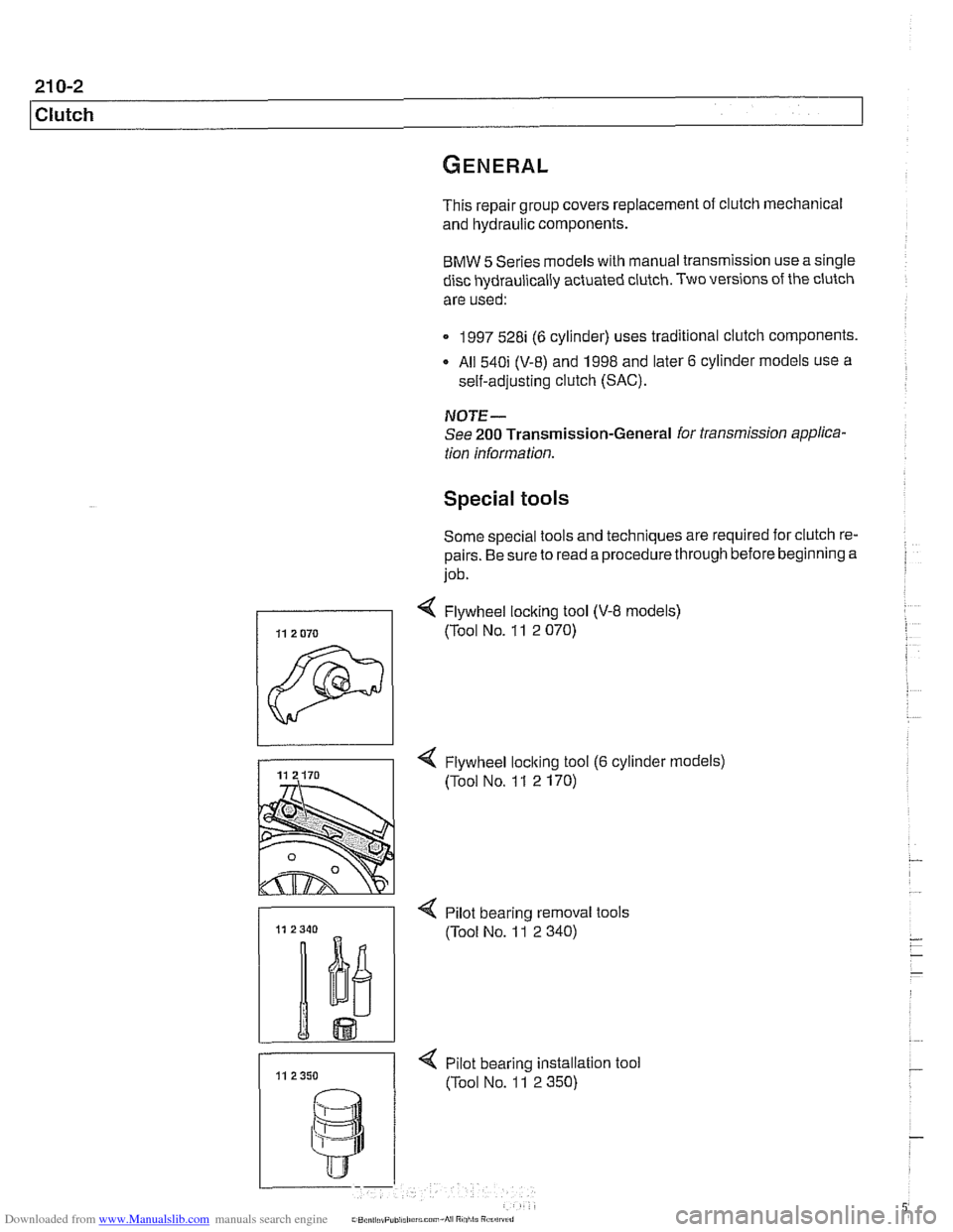
Special tools
Some special tools and techniques are required for clutch re-
pairs. Be sure to read a procedure through before beginning a
job.
< Flywheel loclting tool (V-8 models)
1 (Tool NO. 11 2 070)
-
4 Flywheel loclting tool (6 cylinder models)
(Tool No. 1 1 2 170)
- < Pilot bearino removal tools
11 11 2350 < pilot bearing instaation
(Tool No. 11 2 350) tool
Page 545 of 1002
Downloaded from www.Manualslib.com manuals search engine
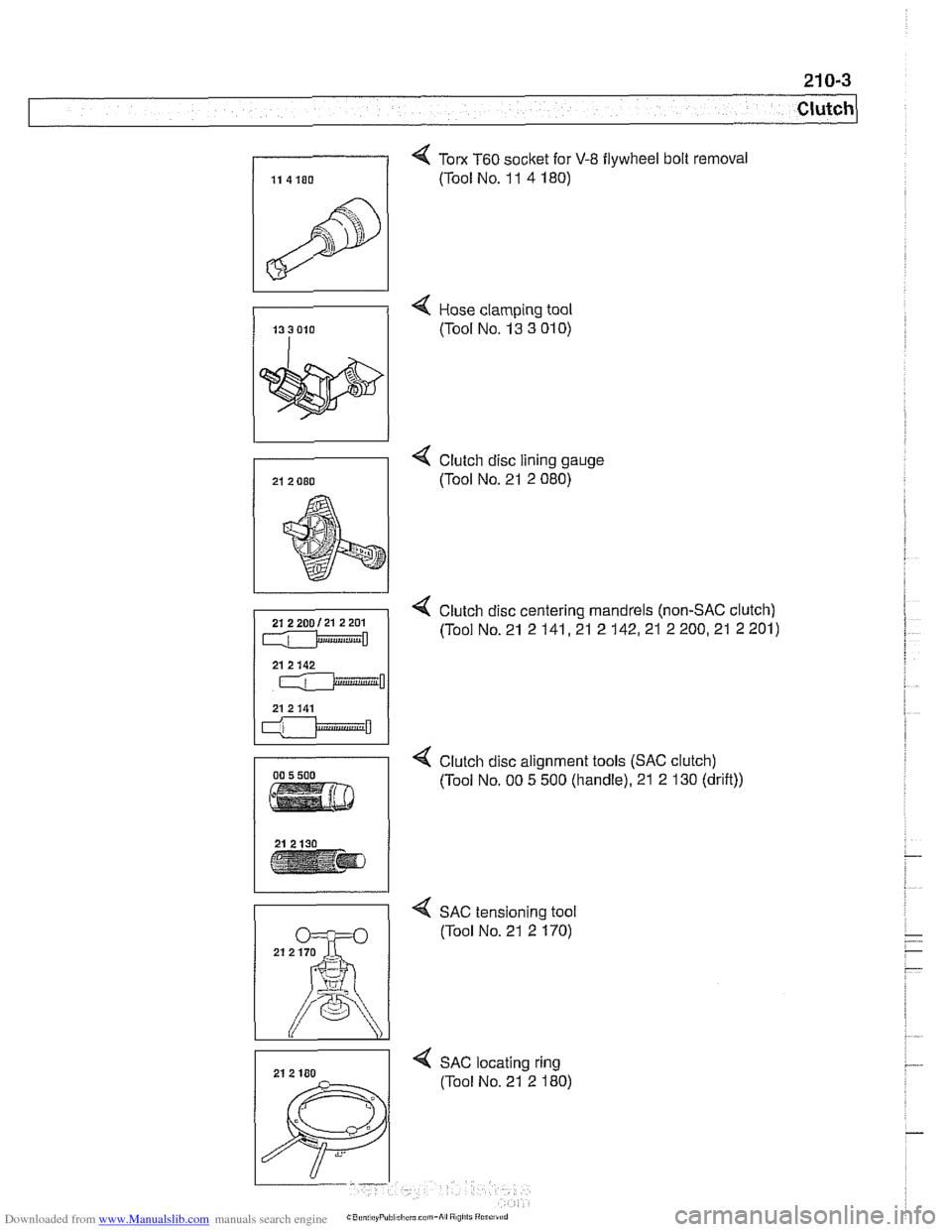
4 Tom T60 socket for V-8 flywheel bolt removal
(Tool No. 1 1 4 180)
4 Hose clamping tool
(Tool No. 13 3
01 0)
4 Clutch disc lining gauge
(Tool No. 21 2 080)
4 Clutch disc centering mandrels (non-SAC clutch)
(Tool No. 21 2
141,21 2 142,21 2 200,21 2 201)
4 Clutch disc alignment tools (SAC clutch)
(Tool No. 00 5 500 (handle). 21 2 130 (drift))
4 SAC tensioning tool
(Tool No. 21 2 170)
4 SAC locating ring
(Tool No. 21 2 180)
Page 546 of 1002
Downloaded from www.Manualslib.com manuals search engine
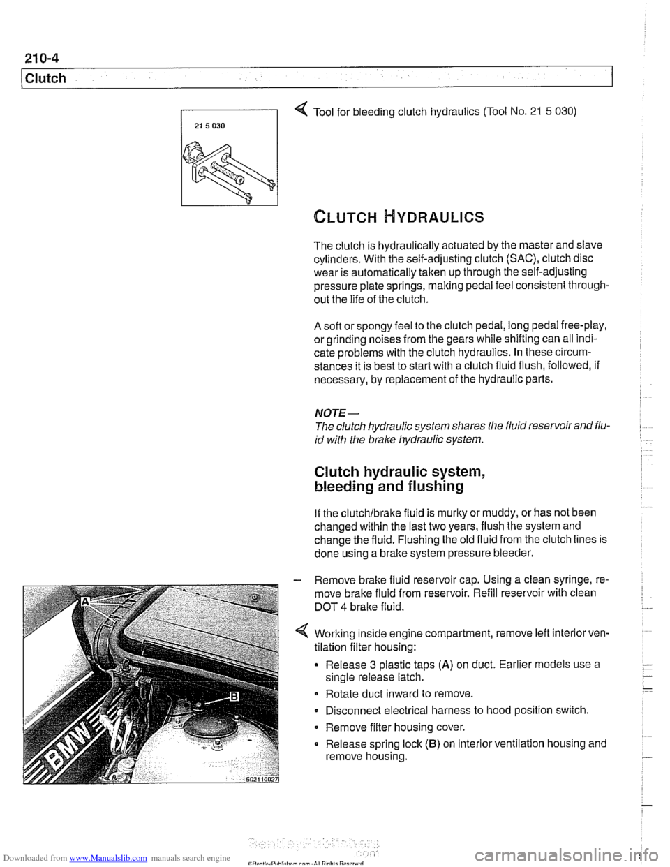
Tool for bleeding clutch hydraulics (Tool No. 21 5 030)
21 5 030 I
The clutch is hydraulically actuated by the master and slave
cylinders. With the self-adjusting clutch
(SAC), clutch disc
wear is automatically taken up through the self-adjusting
pressure plate springs, making pedal feel consistent through-
out the life of the clutch.
A soft or spongy feel to the clutch pedal, long pedal free-play,
or grinding noises
from the gears while shifting can all indi-
cate problems with the clutch hydraulics. In these circum-
stances it is best to
star? with a clutch fluid flush, followed, if
necessary, by replacement of the hydraulic parts.
NOTE-
The clutch hydraulic system shares the fluid reservoir and flu-
id with the brake hydraulic system.
Clutch hydraulic system,
bleeding and flushing
If the clutchlbralte fluid is murky or muddy, or has not been
changed within the last two years, flush the system and
change the fluid. Flushing the old fluid from the clutch lines is
done using a bralte system pressure bleeder.
- Remove brake fluid reservoir cap. Using a clean syringe, re-
move brake fluid from reservoir. Refill reservoir with clean
DOT
4 bralte fluid.
Worlting inside engine compartment, remove left
interiorven-
tilation filter housing:
Release 3 plastic taps
(A) on duct. Earlier models use a
single release latch.
Rotate duct inward to remove.
Disconnect electrical harness to hood position switch.
Remove filter housing cover.
Release spring lock
(B) on interior ventilation housing and
remove housing.
Page 547 of 1002
Downloaded from www.Manualslib.com manuals search engine
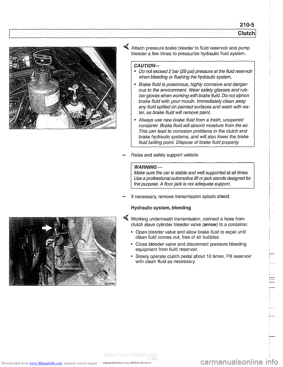
Anach pressure brake bleeder to fluid reservoir and pump
bleeder a few times to pressurize hydraulic fluid system.
CAUTION-
* Do not exceed 2 bar (29 psi) pressure at the fluid resenfoil
when bleeding or flushing the hydraulic system.
Brake fluid is poisonous, highly corrosive and danger-
ous to the environment. Wear safety glasses and
rub-
bergloves when working with brake fluid. Do not siphon
brale fluid with your mouth. Immediately clean away
any fluid spilled on painted surfaces and wash with wa-
ter, as brale fluid will remove paint.
Always use new brake fluid from a fresh, unopened
container.
Brake fluid will absorb moisture from the air.
This can lead to corrosion problems in the clutch and
brake hydraulic systems, ;nd will also lower the brake
fluid boiling point. Dispose of brale fluid properly.
- Raise and safely support vehicle.
WARNING-
Make sure the car is stable and well supported at all times.
Use a professional automotive lift orjackstands designed for
the purpose. A floor
iack is not adequate support.
- If necessary, remove transmission splash shield.
Hydraulic system, bleeding
Worlting underneath transmission, connect a hose from
clutch slave cylinder bleeder valve
(arrow) to a container.
Open bleeder valve and allow bralte fluid to expel until
clean fluid comes out, free of air bubbles.
Close bleeder valve and disconnect pressure bleeding
equipment from fluid reservoir.
Slowly operate clutch pedal about
10 times. Fill reservoir
with clean fluid as necessary.
CR* .,,, .rP,ll,h.:I,,~,~mn.lI","i,,i"
Page 548 of 1002
Downloaded from www.Manualslib.com manuals search engine
21 0-6
1 Clutch
Hydraulic system, bleeding
(using
BMW special tool 21 5 030)
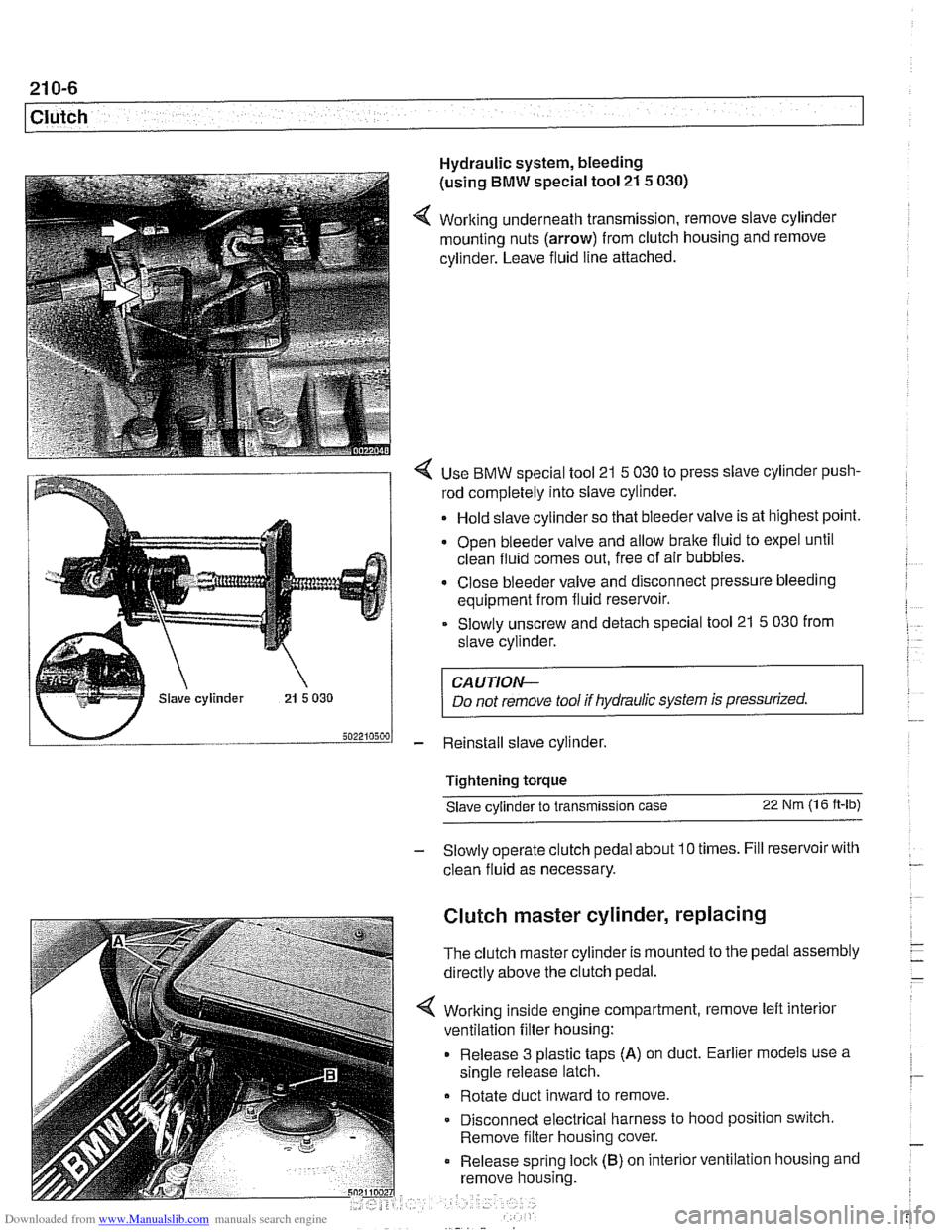
4 Working underneath transmission, remove slave cylinder
mounting nuts (arrow) from clutch housing and remove
cylinder. Leave fluid line attached.
4 Use BMW special tool 21 5 030 to press slave cylinder push-
rod completely into slave cylinder.
Hold slave cylinder so that bleeder valve is at highest point.
Open bleeder valve and allow brake fluid to expel until
clean fluid comes out, free of air bubbles.
* Close bleeder valve and disconnect pressure bleeding
equipment from fluid reservoir.
Slowly unscrew and detach special tool 21
5 030 from
slave cylinder.
CAUTION-
Do not remove tool if hydraulic system is pressurized.
- Reinstall slave cylinder.
Tightening torque Slave cylinder to transmission case
22 Nm (1 6 ft-lb)
- Slowly operate clutch pedal about 10 times. Fill reservoir with
clean fluid as necessary.
Clutch master cylinder, replacing
The clutch master cylinder is mounted to the pedal assembly
directly above the clutch pedal.
Working inside engine compartment, remove left interior
ventilation filter housing:
Release 3 plastic taps
(A) on duct. Earlier models use a
single release latch.
Rotate duct inward to remove
Disconnect electrical harness to hood position switch.
Remove filter housing cover.
Release spring
loclc (B) on interior ventilation housing and
remove housing.
Page 549 of 1002
Downloaded from www.Manualslib.com manuals search engine
21 0-7
Clutch
- Remove brake fluid reservoir cap. Using a clean syringe.
remove brake fluid from reservoir to below level of clutch
hydraulic supply hose.
- Detach clutch hydraulic supply hose from brake fluid reser-
voir. Plug reservoir outlet and hose.
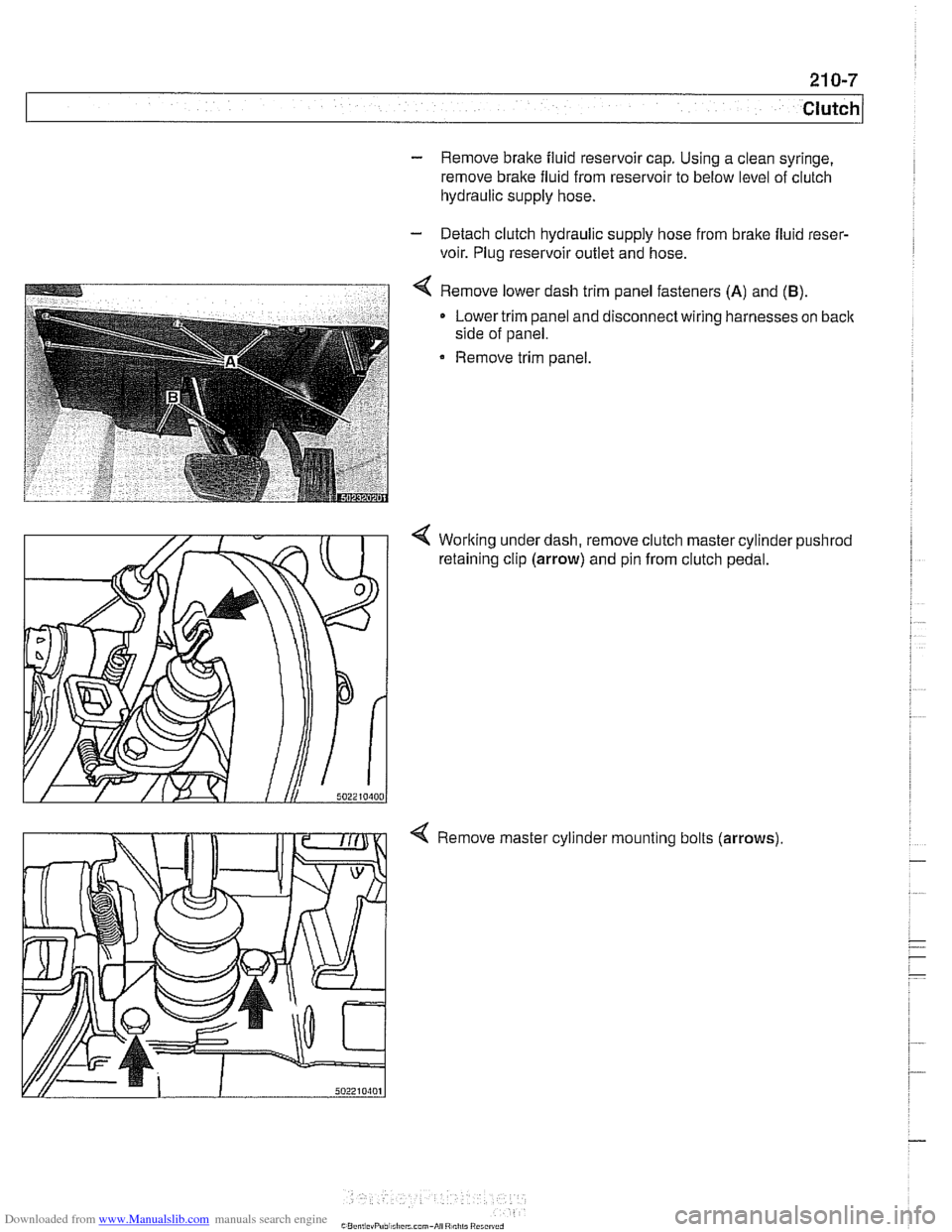
4 Remove lower dash trim panel fasteners (A) and (B).
Lower trim panel and disconnect wiring harnesses on back
side of panel.
Remove trim panel.
4 Working under dash, remove clutch master cylinder pushrod
retaining clip (arrow) and pin from clutch pedal.
4 Remove master cylinder mounting bolts (arrows)
Page 550 of 1002
Downloaded from www.Manualslib.com manuals search engine
21 0-8
Clutch
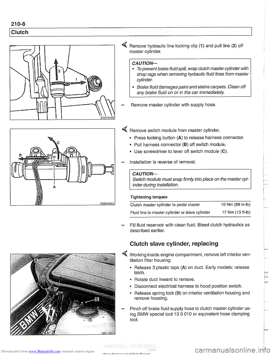
4 Remove hydraulic line locking clip (1) and pull line (2) off
master cylinder.
CAUTION-
. To prevent brake fluidspill, wrap clutch master cylinder with
shop rags when removing hydraulic fluid lines from master
cylinder.
* Brake fluid damages paint andstains carpets. Clean off
any brake fluid on or
in the car immediately.
- Remove master cylinder with supply hose
4 Remove switch module from master cylinder.
Press locking button
(A) to release harness connector.
Pull harness connector
(8) off switch module.
Use screwdriver to lever
off switch module (C).
- Installation is reverse of removal.
CA UTlON-
Switch module must snap firmly into place on the master cyl-
inder during installation.
Tightening torques
Clutch master cylinder to pedal cluster
10 Nm (89 in-lb)
Fluid line
to master cylinder or slave cylinder 17 Nm (13 ft-lb)
- Fill fluid reservoir with clean fluid. Bleed clutch hydraulics as
described earlier.
Clutch slave cylinder, replacing
4 Working inside engine compartment, remove left interiorven-
tilation filter housing:
Release
3 plastic taps (A) on duct. Early models: release
latch.
Rotate duct inward to remove.
Disconnect electrical harness to hood position switch.
Release spring lock (B) on interior ventilation housing and
remove housing.
- Pinch off brake fluid supply hose to clutch master cylinder us-
ing BMW special tool
13 3 01 0 or equivalent hose clamping
tool.