clock BMW M3 1998 E36 Owner's Guide
[x] Cancel search | Manufacturer: BMW, Model Year: 1998, Model line: M3, Model: BMW M3 1998 E36Pages: 759
Page 418 of 759
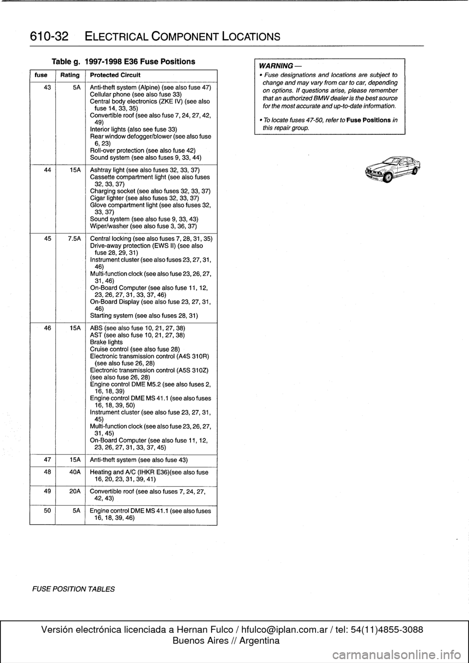
610-32
ELECTRICAL
COMPONENT
LOCATIONS
Tableg
.
1997-1998
E36
Fuse
Positions
fuse
Rating
Protected
Circult
43
5A
Anti-theft
system
(Alpine)
(see
also
f
use47)
Cellular
phone
(seealso
fuse
33)
Central
body
electronics
(ZKE
IV)
(see
alsofuse
14,
33,35)
Convertible
roof
(seealso
fuse
7,
24,
27,
42,49)
Interiorlights
(also
see
fuse
33)
Rear
window
defogger/blower
(see
alsofuse
6,23)
Roll-over
protection
(see
also
fuse
42)
Sound
system
(seealso
fuses
9,
33,
44)
44
15A
Ashtray
light
(seealso
f
uses
32,
33,
37)
Cassette
compartment
light
(seealso
fuses
32,33,
37)
Charging
socket
(seealso
fuses
32,33,
37)
Cigar
lighter
(seealso
fuses
32,33,
37)
Glove
compartment
light
(seealso
f
uses
32,
33,37)
Sound
system
(seealsofuse
9,
33,
43)
Wiper/washer
(seealsofuse
3,
36,
37)
45
7
.5A
Central
locking
(see
also
fuses
7,
28,31,
35)
Drive-away
protection
(EWS
II)
(see
alsofuse
28,
29,31)
Instrument
cluster
(see
also
f
uses
23,27,31,
46)
Multi-function
clock
(see
also
f
use
23,26,27,
31,46)
On-Board
Computer
(see
alsofuse
11,
12,23,
26,27,
31,33,37,
46)
On-Board
Display
(seealsofuse
23,27,31,
46)
Starting
system
(seealso
fuses
28,31)
46
15A
ABS
(see
also
fuse
10,21,27,
38)
AST
(seealsofuse
10,
21,27,
38)
Brake
lights
Cruise
control
(see
also
fuse
28)
Electronic
transmission
control
(A4S
310R)
(see
also
fuse
26,
28)
Electronic
transmission
control
(A5S
310Z)
(see
also
f
use
26,28)
Engine
control
DME
M5
.2
(see
also
fuses
2,
16,18,
39)
Engine
control
DME
MS
41
.1
(seealso
fuses
16,18,39,
50)
Instrument
cluster
(see
also
fuse
23,27,31,
45)
Multi4unction
clock
(see
also
fuse
23,26,27,
31,45)
On-Board
Computer
(seealsofuse
11,
12,23,26,27,
31,
33,37,
45)
47
1
15A
1
Anti-theft
system
(see
also
fuse
43)
48
40A
Heating
and
A/C
(IHKR
E36)(see
also
fuse
16,20,23,
31,
39,
41)
49
20A
Convertible
roof
(see
also
fuses
7,
24,
27,
42,43)
50
5A
Engine
control
DME
MS
41
.1
(seealso
fuses
16,18,39,
46)
FUSE
POSITION
TABLES
WARNING
-
"
Fuse
designations
and
locations
are
subject
to
change
and
may
vary
fromcar
to
car,
depending
on
options
.
If
questions
arise,
please
remember
that
an
authorized
BMW
dealer
is
the
bestsource
for
the
most
accurate
and
up-to-date
information
.
"
Tolocate
fuses
47-50,
refer
to
Fuse
Positions
inthis
repair
group
.
Page 440 of 759
620-
4
INSTRUMENTS
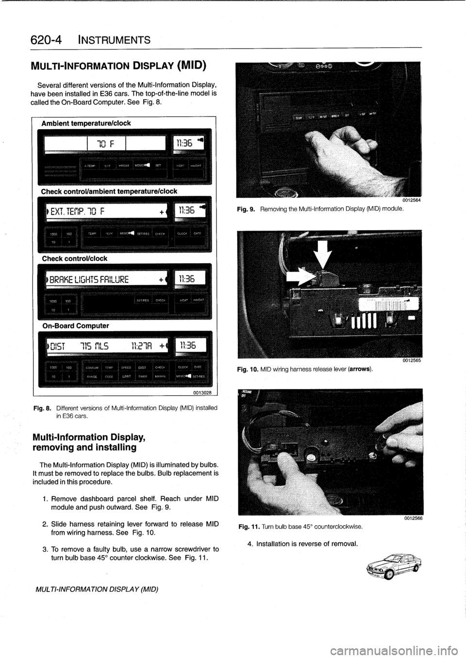
MULTI-INFORMATION
DISPLAY
(MID)
Severa¡
different
versionsof
the
Multi-Information
Display,
have
been
installed
in
E36
cars
.
The
top-of-the-line
model
is
called
the
Oh-BoardComputer
.
See
Fig
.
8
.
Ambient
temperature/ciock
Check
control/clock
0013028
Fig
.
8
.
Different
versions
of
Multi-Information
Display
(MID)
installed
in
E36
cars
.
Multi-Information
Display,
removing
and
installing
The
Multi-Information
Display
(MID)
is
illuminated
by
bulbs
.
It
mustbe
removed
to
replace
the
bulbs
.
Bulb
replacement
is
included
in
this
procedure
.
1
.
Remove
dashboard
parcel
shelf
.
Reach
under
MID
module
and
pushoutward
.
See
Fig
.
9
.
2
.
Slide
harness
retaining
lever
forward
to
release
MID
from
wiring
harness
.
See
Fig
.
10
.
3
.
To
Rmove
a
faulty
bulb,
use
anarrow
screwdriver
to
turn
bulb
base
45°
counter
clockwíse
.
See
Fig
.
11
.
MULTI-INFORMATIONDISPLAY
(MID)
111
Fig
.
9
.
Removing
the
Multi-Information
Display(MID)
module
.
0012564
Fig
.
10
.
MID
wiring
harness
release
lever
(arrows)
.
Fig
.
11
.
Turn
bulb
base
45°
counterclockwise
.
4
.
Installation
is
reverse
of
removal
.
0012566
Page 441 of 759
FRONT
LIGHTING
.
...........
.
....
.
.
.
.
630-1
Headlight
buib,
replacing
............
.
.
.
.
630-1
Headlight
assembly,
removing
and
installing
.......
.
....
.
.
.
.
630-2
Foglight
assembly,
removing
and
installing
..
630-3
Front
turn
signal
assembly,
removing
and
installing
.....
.
.
.
........
630-4
GENERAL
The
headlight
and
foglight
assemblies
usehalogen
bulbs
.
To
ensure
the
longevity
of
halogen
bulbs,
the
bulb
glass
should
not
be
handied
.
Dirt
and
skin
oíls
may
cause
a
bulbto
fail
prematurely
.
If
necessarywipe
bulb
using
a
clean
cloth
dampened
with
rubbing
alcohol
.
NOTE-
Use
only
original
equipment
replacement
bulbs
.
Non-
original
equipment
bulbs
may
cause
false
failure
read-
ings
on
the
check
control
display
(where
applicable)
.
WARNING
-
INhenworking
on
electrical
systems,
remove
the
fuse
protecting
the
circuit
under
repair
.
See
610
Electrical
Component
Locations
.
FRONT
LIGHTING
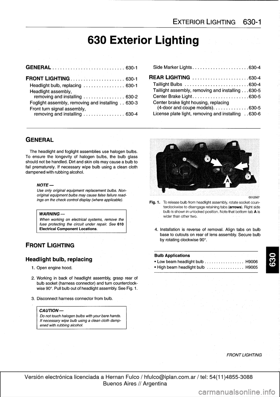
Headlight
bulb,
replacing
1
.
Open
engine
hood
.
2
.
Working
in
back
of
headlight
assembly,grasp
rear
of
bulbsocket
(harnessconnector)
and
turn
counterclock-
wise
90°
.
Pull
bulb
out
of
headlight
assembly
.
See
Fig
.
1
.
3
.
Disconnect
harness
connector
from
bulb
.
CA
UTION-
Do
not
touch
halogen
bubs
with
yourbare
hands
.
If
necessary
wipe
bulb
using
a
clean
cloth
damp-
ened
with
rubbing
alcohol
.
630
Exterior
Lighting
EXTERIOR
LIGHTING
630-1
GENERAL
.
.
.
.
...
.
................
.
.
.
.
630-1
Side
Marker
Lights
.......
.
.
.
.
.
.......
.
..
630-4
REAR
LIGHTING
.
......
.
.
.
.
.
.
.
...
.
.
.
..
630-4
Taillight
Bulbs
..........
.
.
.
.
.
.....
.
.
.
.
.
630-4
Taillight
assembly,
removing
and
installing
.
.
.
630-5
CenterBrake
Light
.......
.
.
.
.
.
.
.
.
.
.
.
.
.
.
.
630-5
Center
brake
light
housing,
replacing
(4-door
and
coupe
models)
.
.
.
.
.......
.
.
.630-5
License
plate
light,
removingand
installing
.
.630-6
0012567
Fig
.1.
Torelease
bulbfrom
headlight
assembly,
rotate
socket
coun-
terclockwise
to
disengage
retaining
tabs
(arrows)
.
Right
side
bulb
is
shown
in
unlocked
position
.
Note
that
bottom
tab
A
is
wider
than
other
two
.
4
.
Installation
is
reverse
of
removal
.
Align
tabs
on
bulb
base
to
cutouts
on
rear
of
lens
assembly
.
Secure
bulb
by
rotating
clockwise
90°
.
Bulb
Applications
"
Low
beam
headlight
bulb
...
.
..
..
.........
H9006
"
High
beam
headlight
bulb
..
.
..
..
.........
H9005
FRONT
LIGHTING
Page 444 of 759
630-
4
EXTERIOR
LIGHTING
Front
turn
signal
assembly,
Side
Marker
Lights
removing
and
installing
Side
marker
lights
on
later
model
E36
cars
are
snapped
into
The
procedurebelow
also
includes
turn
signal
bulb
replace-
the
front
fenders
.
To
service,
carefully
pry
the
assembly
out
of
ment
.
the
fender,
then
detach
the
electrical
harness
connector
and
bulb
socket
.
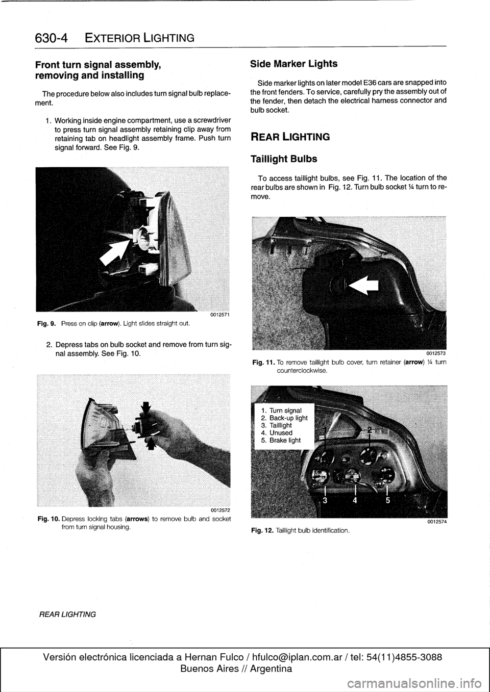
1
.
Working
inside
engine
compartment,usea
screwdriver
to
press
turn
signal
assembly
retaining
clip
away
from
retaining
tab
on
headlight
assembly
frame
.
Push
turn
REAR
LIGHTING
signal
forward
.
See
Fig
.
9
.
Fig
.
9
.
Press
on
clip
(arrow)
.
Light
slides
straight
out
.
REAR
LIGHTING
0012571
2
.
Depress
tabs
on
bulb
socket
and
remove
from
turn
sig-
nal
assembly
.
See
Fig
.
10
.
0012572
Fig
.
10
.
Depress
locking
tabs
(arrows)to
remove
bulb
and
socket
from
turn
signal
housing
.
Taillight
Bulbs
To
access
taillight
bulbs,
see
Fig
.
11
.
The
location
of
the
rear
bulbs
are
shown
in
Fig
.
12
.
Turn
bulb
socket
1
/4turn
to
re-
move
.
Fig
.
11
.
To
remove
taillight
bulb
cover,
turn
retainer
(arrow)
1
/a
turn
counterclockwise
.
Fig
.
12
.
Taillight
bulb
identification
.
0012574
Page 445 of 759
Taillight
assembly,
removing
and
installing
1
.
Open
trunk
lid
.
Remove
cover
from
rear
of
taillight
.
Re-
fer
to
Fig
.
11
.
2
.
Depress
locking
tabs
on
electrical
harness
convector
and
disconnect
from
rear
of
taillight
lens
assembly
.
Re-
move
four
taillight
assembly
retaining
nuts
.
See
Fig
.
13
.
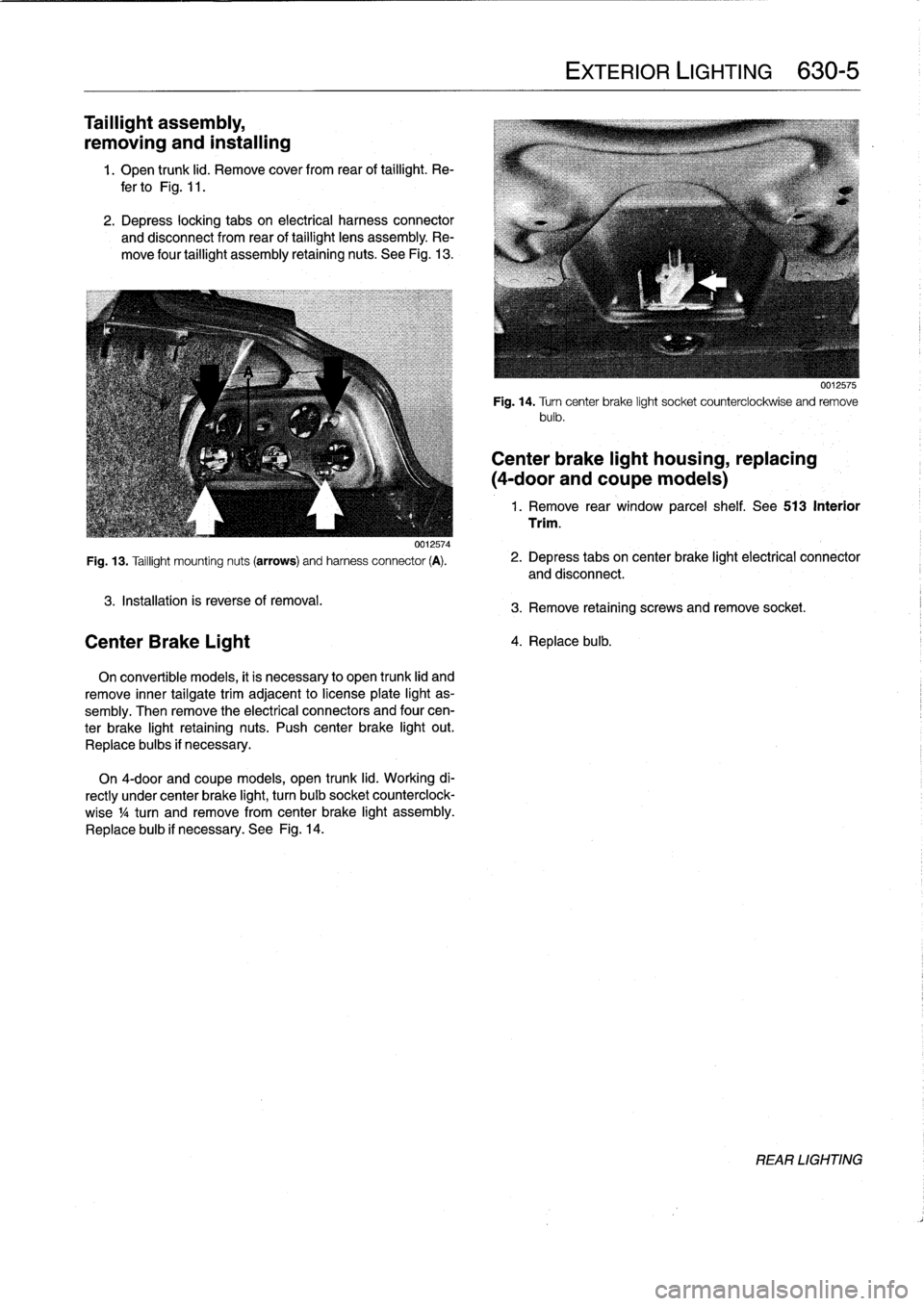
0012574
Fig
.
13
.
Taillight
mounting
nuts
(arrows)
and
harness
connector
(A)
.
3
.
Installation
is
reverse
of
removal
.
Center
Brake
Light
On
convertible
models,
it
is
necessary
to
open
trunk
lid
and
remove
inner
tailgatetrim
adjacent
to
license
plate
light
as-
sembly
.
Then
remove
the
electrical
connectors
and
four
cen-
ter
brake
light
retaining
nuts
.
Push
center
brake
light
out
.
Replace
bulbs
if
necessary
.
On
4-door
and
coupe
models,
open
trunk
lid
.
Working
di-
rectly
under
center
brake
light,
turn
bulb
socket
counterclock-
wise
1
/4turn
andremove
from
center
brake
light
assembly
.
Replace
bulb
if
necessary
.
See
Fig
.
14
.
EXTERIOR
LIGHTING
630-
5
0012575
Fig
.
14
.
Turncenter
brake
light
socket
counterclockwise
and
remove
bulb
.
Center
brake
light
housing,
replacing
(4-door
andcoupe
models)
1
.
Remove
rear
window
parcel
shelf
.
See513
Interior
Trim
.
2
.
Depress
tabs
on
center
brake
light
electrical
connector
and
disconnect
.
3
.
Remove
retaining
screws
and
remove
socket
.
4
.
Replace
bulb
.
REAR
LIGHTING
Page 458 of 759
640-12
HEATING
AND
AIR
CONDITIONING
A/C
Compressor,
replacing
1
.
Followingmanufacturer's
instructions,
connectanap-
proved
refrigerant
recovery/recycling/recharging
unit
to
A/C
system
and
discharge
system
.
WARNING
-
Do
notdischarge%harge
the
AIC
system
without
proper
equipment
and
training
.
Damage
to
the
vehi-
cle
and
personal
injury
may
result
.
2
.
Remove
splash
shield
fromunder
engine
.
3
.
Mark
A/C
drive
belt
with
direction
ofrotation
.
Remove
A/C
belt
tensioner
trim
cap
.
See
Fig
.
34
.
0011988
Fig
.
34
.
To
access
tensioner
retaining
bolt,
remove
trim
cap
from
drive-belt
tensioner
.
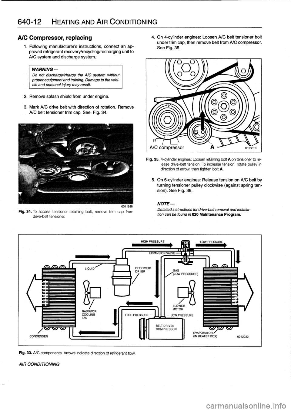
Fig
.
33
.
A/
C
components
.
Arrows
indicatedirection
of
refrigerant
flow
.
AIR
CONDITIONING
4
.
On
4-cylinder
engines
:
Loosen
A/C
belt
tensioner
bolt
under
trim
cap,
then
remove
belt
from
A/C
compressor
.
See
Fig
.
35
.
~=1
A/C
compressor
A
0013019
Fig
.
35
.
4-cylinder
engines
:
Loosen
retaining
bolt
A
on
tensionerto
re-
lease
drive-belt
tension
.
To
increase
tension,
rotate
pulley
in
direction
of
arrow,
then
tighten
bolt
A
.
5
.
On
6-cylinder
engines
:
Release
tension
on
A/C
belt
by
turning
tensioner
pulley
clockwíse
(againstspring
ten-
sion)
.
See
Fig
.
36
.
NOTE
-
Detailed
instructions
for
drive-belt
removal
and
installa-tion
can
be
found
in
020
Maintenance
Program
.
Page 459 of 759
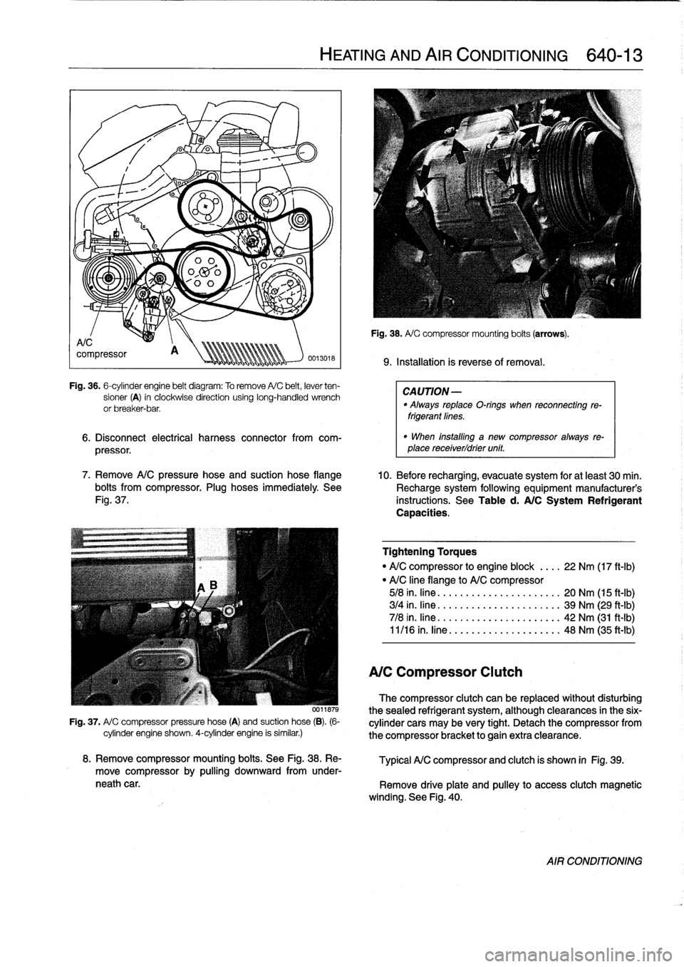
Fig
.
36
.
6-cylinder
engine
belt
diagram
:
To
remove
A/C
belt,
lever
ten-
sioner
(A)
in
clockwise
direction
using
long-handled
wrench
or
breaker-bar
.
6
.
Disconnect
electrical
harness
connector
from
com-
pressor
.
7
.
Remove
A/C
pressure
hose
and
suction
hose
flange
10
.
Before
recharging,
evacuate
system
for
at
least
30
min
.
bolts
from
compressor
.
Plug
hoses
immediately
See
Recharge
system
following
equipment
manufacturer's
Fig
.
37
.
instructions
.
See
Table
d
.
A/C
System
Refrigerant
Capacities
.
0011879
Fig
.
37
.
A/
C
compressor
pressure
hose
(A)
and
suction
hose
(B)
.
(6-
cylinder
engine
shown
.
4-cylinder
engine
is
similar
.)
HEATING
AND
AIR
CONDITIONING
640-
1
3
Fig
.
38
.
A/
C
compressor
mounting
boits
(arrows)
.
9
.
Installation
is
reverseof
removal
.
CAUTION
-
"
Always
replaceO-rings
when
reconnecting
re-
frigerantfines
.
"
When
installlng
a
new
compressor
always
re-
place
receiverldrier
unit
.
Tightening
Torques
"
A/C
compressor
to
engine
block
....
22
Nm
(17
ft-Ib)
"
A/C
line
flange
to
A/C
compressor
5/8
in
.
fine
.
......
.....
....
.
.....
20
Nm
(15
ft-Ib)
3/4
in
.
fine
.......
.....
..........
39
Nm
(29
ft-Ib)
7/8
in
.
fine
...
....
.....
..........
42
Nm
(31
ft-Ib)
11/16
in
.
fine
.....
..
..
..
...
.
.....
48
Nm
(35
ft-Ib)
A/C
Compressor
Clutch
The
compressor
clutch
can
be
replaced
without
disturbing
thesealed
refrigerant
system,
although
clearances
in
the
six-
cylinder
cars
may
be
very
tight
.
Detach
the
compressor
from
the
compressor
bracket
togain
extra
clearance
.
8
.
Remove
compressor
mounting
boits
.
See
Fig
.
38
.
Re-
Typical
A/C
compressor
and
clutch
is
shown
in
Fig
.
39
.
move
compressor
by
pulling
downward
from
under-
neath
car
.
Remove
driveplate
and
pulley
to
access
clutch
magnetic
winding
.
See
Fig
.
40
.
AIR
CONDITIONING
Page 464 of 759
640-18
HEATING
AND
AIR
CONDITIONING
A/C
microfilter,
replacing
1
.
Remove
glove
compartment
.
See
513
Interior
Trim
.
2
.
Remove
right
footwell
ventilation
duct
.
See
Fig
.
51
.
0012664
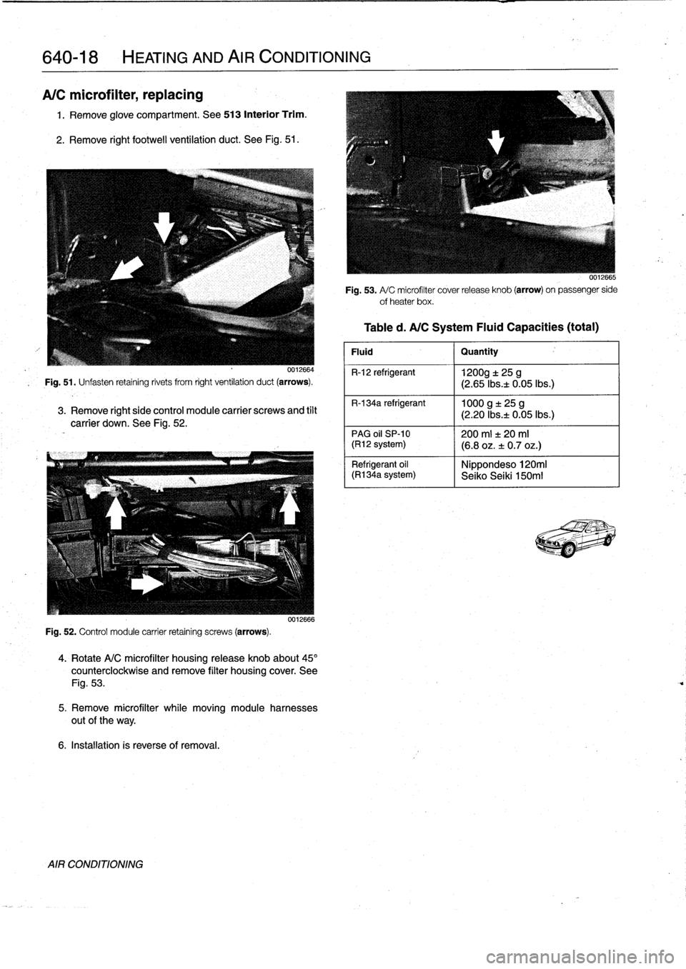
Fig
.
51
.
Unfasten
retaining
rivets
from
right
ventilation
duct
(arrows)
.
3
.
Remove
right
side
control
module
carrier
screws
and
tilt
carrier
down
.
See
Fig
.
52
.
Fig
.
52
.
Control
module
carrier
retaining
screws
(arrows)
.
0012666
4
.
Rotate
A/C
microfilter
housing
release
knob
about45°
counterclockwise
and
remove
filter
housing
cover
.
See
Fig
.
53
.
5
.
Remove
microfilter
while
moving
module
harnesses
out
of
the
way
.
6
.
Installation
is
reverse
of
removal
.
AIR
CONDITIONING
Fig
.
53
.
A/
C
microfilter
cover
release
knob
(arrow)
on
passenger
side
ofheater
box
.
Table
d
.
A/CSystem
Fluid
Capacities
(total)
Fluid
I
Quantity
R-12
refrigerant
1200g
t
25
g
(2
.65
Ibsa
0
.05lbs
.)
R-134a
refrigerant
1000
g
±
25
g
(2
.20
Ibs
.t
0
.05lbs
.)
PAG
oil
SP-10
1200
ml
f
20
ml(R12
system)
(6
.8
oz
.
±
0
.7
oz
.)
Nippondeso120mi
Refrigerant
oil
(R1
34a
system)
I
Seiko
Seiki
150m1
Page 467 of 759
2
.
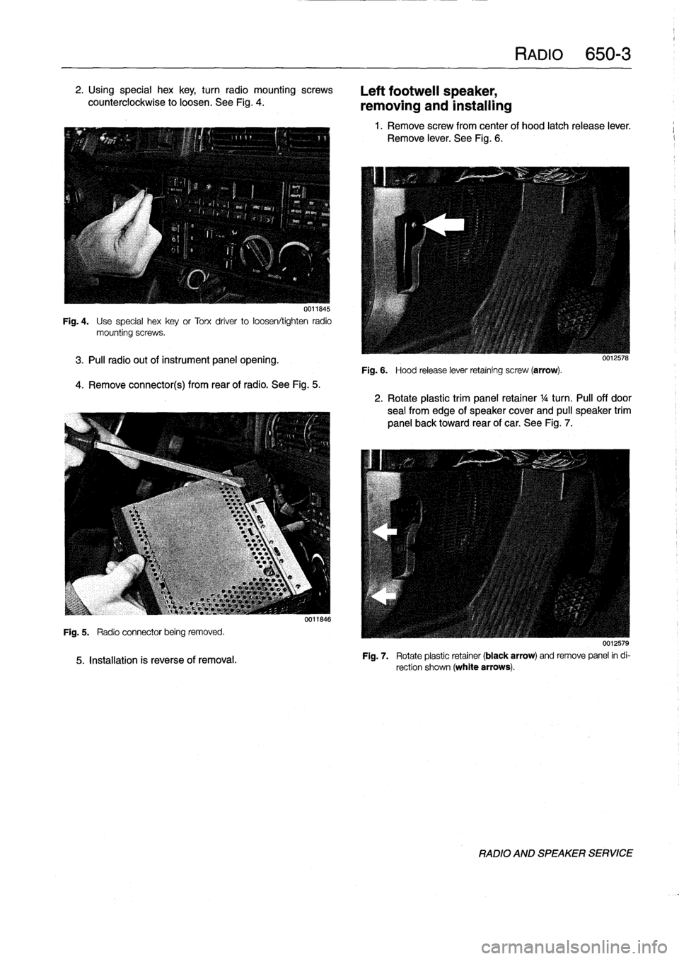
Using
special
hex
key,
turn
radio
mountingscrews
counterclockwise
to
loosen
.
See
Fig
.
4
.
0011845
Fig
.
4
.
Use
special
hexkey
or
Torx
driver
to
loosen/tighten
radio
mountingscrews
.
3
.
Pul¡
radio
out
of
instrument
panel
opening
.
4
.
Remove
connector(s)
from
rearof
radio
.
See
Fig
.
5
.
Fig
.
5
.
Radio
connector
being
removed
.
5
.
Installation
is
reverse
of
removal
.
0011846
Left
footweil
speaker,
removing
and
installing
Fig
.
6
.
Hood
release
lever
retaining
screw
(arrow)
.
RADIO
650-
3
1
.
Remove
screw
from
center
of
hood
latch
release
lever
.
Remove
lever
.
See
Fig
.
6
.
0012578
2
.
Rotate
plastic
trim
panel
retainer
1
/4
turn
.
Pul¡
off
door
sea¡
from
edge
of
speaker
cover
and
pull
speaker
trim
panel
back
toward
rear
of
car
.
See
Fig
.
7
.
0012579
Fig
.
7
.
Rotate
plastic
retainer
(black
arrow)
andremove
panel
in
di-
rection
shown
(white
arrows)
.
RADIO
AND
SPEAKER
SERVICE
Page 472 of 759
720-2
SEAT
BELTS
WARNING
-
"
For
maximum
protection
from
injury,
seat
belts
should
be
replaced
as
a
set
(including
all
hard-
ware),
if
they
are
subject
to
occupant
loading
in
a
collision
.
"
Seat
belts
should
not
be
modified
or
repaired
.
The
seat
belt
anchorage
points
should
not
be
changed
or
modified
.
"
Do
notbleach
or
dye
seat
belt
webbing
.
Webbing
that
is
severely
fadedor
re-dyed
will
not
meet
the
strength
requirements
of
a
collision
and
must
be
replaced
.
"
Seat
belts
shouldbe
periodically
inspected
for
webbing
defects
suchas
cuts
or
pulled
threads
.
FRONT
SEATBELT
ASSEMBLY
Automatic
Front
Seat
Belt
Lock
Tensioners
The
procedure
for
disabling
the
mechanical
spring
tension-
er
used
on
early
cars
is
covered
below
.
On
cars
with
thepyro-
technic(explosive
device)
tensioners,
the
orange
harness
connectorshould
be
removed
from
the
tensioner
any
time
the
seat
is
removed
.
WARNING
-
Both
the
mechanical
and
the
pyrotechnictensioners
are
powerful
devíces
and
shouldbehandled
with
extreme
care
.
Mechanical
spring
tensioner,
disarming
1
.
Remove
front
seat
.
See
520
Seats
.
2
.
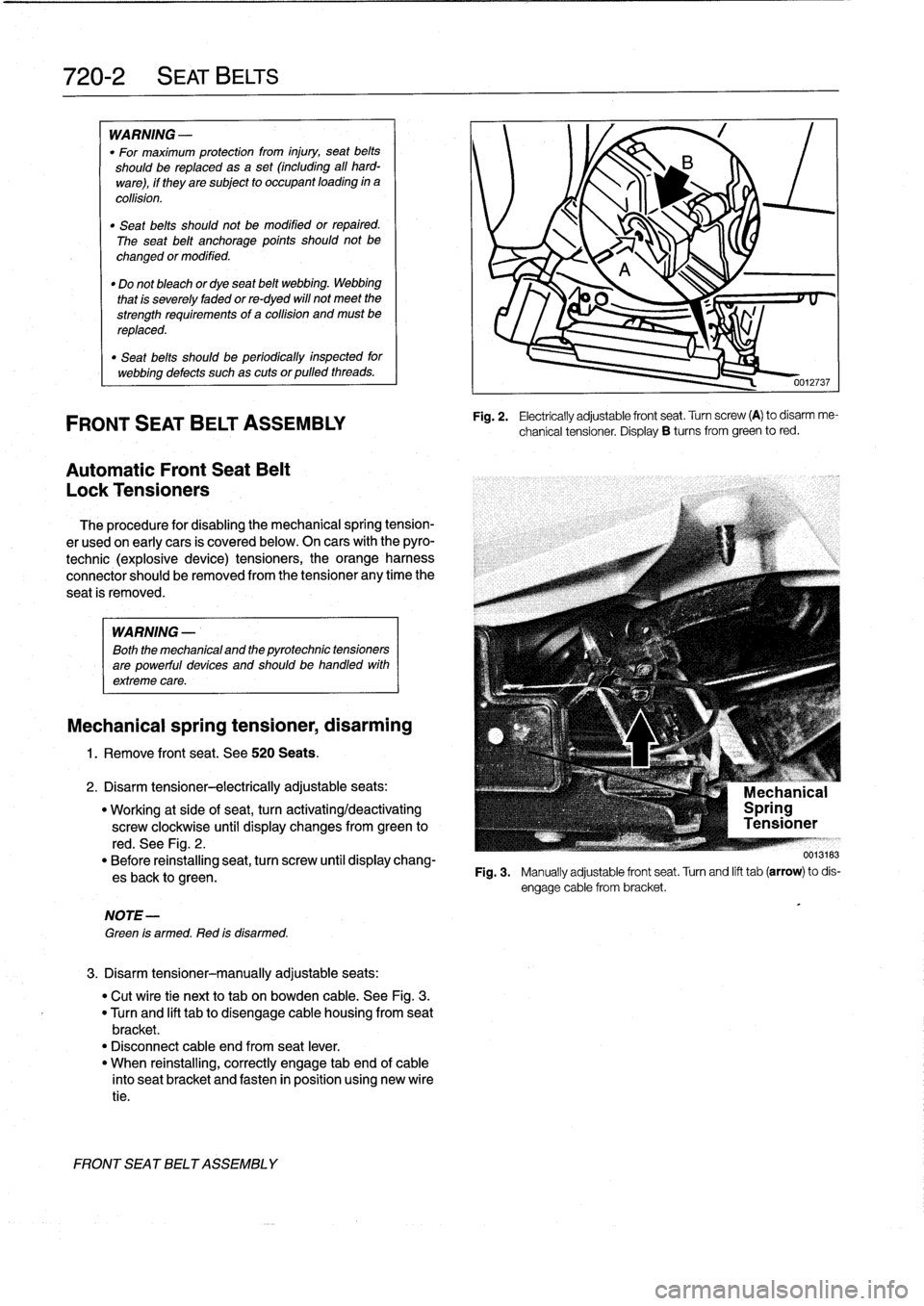
Disarm
tensioner-electrically
adjustableseats
:
"
Working
at
side
of
seat,
turn
activating/deactivating
screw
clockwise
until
display
changes
from
green
to
red
.
See
Fig
.
2
.
"
Before
reinstalling
seat,
turn
screw
until
display
chang-
esback
to
green
.
NOTE-
Green
is
armed
.
Red
is
disarmed
.
3
.
Disarm
tensioner-manually
adjustable
seats
:
"
Cut
wíre
tie
next
to
tab
on
bowden
cable
.
See
Fig
.
3
.
"
Turn
and
lift
tabto
disengage
cable
housing
from
seat
bracket
.
"
Disconnect
cable
end
from
seat
lever
.
"
When
reinstalling,
correctly
engage
tab
end
of
cable
into
seat
bracket
and
fasten
in
position
using
new
wíre
tie
.
FRONT
SEATBELT
ASSEMBLY
0012737
Fig
.
2
.
Electrically
adjustable
front
seat
.
Turn
screw
(A)
to
disarm
me-
chanical
tensioner
.
Display
B
tucos
from
green
to
red
.
F19
.3
.
Manuallyadjustablefrontseat
.Turnandlifttab(arrow)todis-