ECO mode BMW M6 CONVERTIBLE 2013 F12 User Guide
[x] Cancel search | Manufacturer: BMW, Model Year: 2013, Model line: M6 CONVERTIBLE, Model: BMW M6 CONVERTIBLE 2013 F12Pages: 222, PDF Size: 7.3 MB
Page 88 of 222

Gear display with Drivelogic
Sequential mode▷Engaged gear, arrow 1.▷Selected driving program,
Drivelogic, refer to page 72,
arrow 2.
Drive mode
▷Engaged gear together with
a D, arrow 1.▷Selected driving program,
Drivelogic, refer to page 72,
arrow 2.
Range
After the reserve range is
reached:
▷A Check Control message is
displayed briefly.▷The remaining range is
shown on the computer.▷When a dynamic driving style is used, such
as when cornering quickly, operation of the
engine is not always ensured.
The Check Control message appears continu‐
ously below a range of approx. 30 miles/50 km.
Refuel promptly
Refuel no later than at a range of
30 miles/50 km, or operation of the engine is
not ensured and damage may occur.◀
Displaying the cruising range
1."Settings"2."Info display"3."Range"
The range is displayed in the instrument clus‐
ter.
Range when destination guidance is
activated in the navigation system
When destination guidance is
activated in the navigation sys‐
tem, the range up to the desti‐
nation is displayed.
Current fuel consumption Displays the current fuel con‐
sumption. You can check whether you are currently driv‐
ing in an efficient and environ‐
mentally-friendly manner.
Displaying the current fuel
consumption1."Settings"2."Info display"3.If necessary, "M dynamic driving syst."
The display for the current fuel con‐
sumption is active.
Display of the dynamic driving sys‐
tems, refer to page 85.
The bar display for the current fuel consump‐
tion is displayed in the instrument cluster.
Energy recovery The kinetic energy of the vehicle
is converted to electrical energy
while coasting. The vehicle bat‐
tery is partially charged and fuel
consumption can be lowered.
Displaying energy recovery
1."Settings"2."Info display"3.If necessary, "M dynamic driving syst."Seite 84ControlsDisplays84
Online Edition for Part no. 01 40 2 910 746 - VI/13
Page 90 of 222
Detailed information on service
requirements
More information on the scope of service re‐
quired can be displayed on the Control Dis‐
play.1."Vehicle Info"2."Vehicle status"3. "Service required"
Required maintenance procedures and le‐
gally mandated inspections are displayed.4.Select an entry to call up detailed informa‐
tion.
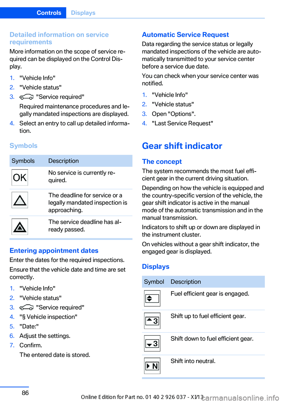
Symbols
SymbolsDescriptionNo service is currently re‐
quired.The deadline for service or a
legally mandated inspection is
approaching.The service deadline has al‐
ready passed.
Entering appointment dates
Enter the dates for the required inspections.
Ensure that the vehicle date and time are set
correctly.
1."Vehicle Info"2."Vehicle status"3. "Service required"4."§ Vehicle inspection"5."Date:"6.Adjust the settings.7.Confirm.
The entered date is stored.Automatic Service Request
Data regarding the service status or legally
mandated inspections of the vehicle are auto‐
matically transmitted to your service center
before a service due date.
You can check when your service center was
notified.1."Vehicle Info"2."Vehicle status"3.Open "Options".4."Last Service Request"
Gear shift indicator
The conceptThe system recommends the most fuel effi‐
cient gear in the current driving situation.
Depending on how the vehicle is equipped and
the country-specific version of the vehicle, the
gear shift indicator is active in the manual
mode of the automatic transmission and in the
manual transmission.
Indicators to shift up or down are displayed in
the instrument cluster.
On vehicles without a gear shift indicator, the
engaged gear is displayed.
Displays
SymbolDescriptionFuel efficient gear is engaged.Shift up to fuel efficient gear.Shift down to fuel efficient gear.Shift into neutral.Seite 86ControlsDisplays86
Online Edition for Part no. 01 40 2 910 746 - VI/13
Page 97 of 222

LampsVehicle equipment
All standard, country-specific and optional
equipment that is offered in the model series is
described in this chapter. Therefore, equip‐
ment is also described that is not available in a
vehicle, e. g., because of the selected optional
equipment or country variant. This also applies
for safety-related functions and systems.
At a glance1Rear fog lamps2Automatic headlamp control, Adaptive
Light Control, High-beam Assistant, Wel‐
come lamps, Daytime running lights3Lamps off, daytime running lights4Parking lamps, daytime running lights5Low beams, welcome lamps, High-beam
Assistant6Instrument lighting
Parking lamps/low beams,
headlamp control
General information Switch position: 0,
,
If the driver door is opened with the ignition
switched off, the exterior lighting is automati‐
cally switched off at these switch settings.
Parking lamps
Switch position
: the vehicle lamps light
up on all sides, e.g., for parking.
Do not use the parking lamps for extended pe‐
riods; otherwise, the battery may become dis‐
charged and it would then be impossible to
start the engine.
When parking, it is preferable to switch on the
one-sided roadside parking lamps, refer to
page 94.
Low beams Switch position
with the ignition switched
on: the low beams light up.
Welcome lamps When parking the vehicle, leave the switch in
position
or : the parking and interior
lamps light up briefly when the vehicle is un‐
locked.
Activating/deactivating
1."Settings"2."Lighting"3."Welcome lights"
The setting is stored for the remote control
currently in use.
Headlamp courtesy delay feature
The low beams stay lit for a short while after
the ignition is switched off, if the lamps are
switched off and the headlamp flasher is
switched on.
Setting the duration
1."Settings"2."Lighting"3."Pathway lighting:"4.Set the duration.Seite 93LampsControls93
Online Edition for Part no. 01 40 2 910 746 - VI/13
Page 123 of 222

Driving stability control systemsVehicle equipmentAll standard, country-specific and optional
equipment that is offered in the model series is
described in this chapter. Therefore, equip‐
ment is also described that is not available in a
vehicle, e. g., because of the selected optional
equipment or country variant. This also applies
for safety-related functions and systems.
Antilock Brake System ABS ABS prevents locking of the wheels during
braking.
The vehicle remains steerable even during full
brake applications, thus increasing active
safety.
ABS is operational every time you start the en‐
gine.
Brake assistant
When you apply the brakes rapidly, this system
automatically produces the maximum braking
force boost. This then reduces braking dis‐ tance to a minimum during full braking. This
system utilizes all of the benefits provided by ABS.
Do not reduce the pressure on the brake pedal
for the duration of the full braking.
Drive-off assistantThis system supports driving away on gradi‐
ents. The parking brake is not required.1.Hold the vehicle in place with the foot
brake.2.Release the foot brake and drive away
without delay.After the foot brake is released, the vehicle is
held in place for approx. 2 seconds.
Depending on the vehicle load, the vehicle may
roll back slightly.
Driving off without delay
After releasing the foot brake, start driv‐
ing without delay, since the drive-off assistant
will not hold the vehicle in place for more than
approx. 2 seconds and the vehicle will begin
rolling back.◀
DSC Dynamic Stability
Control
The concept DSC prevents traction loss in the driving
wheels when driving away and accelerating.
DSC also recognizes unstable vehicle condi‐
tions, such as fishtailing or nose-diving. Sub‐
ject to physical limits, DSC helps to keep the
vehicle on a steady course by reducing engine
speed and by applying brakes at individual
wheels.
Adjust your driving style to the situation
An appropriate driving style is always the
responsibility of the driver.
The laws of physics cannot be repealed, even
with DSC.
Therefore, do not reduce the additional safety
margin by driving in a risky manner.◀
Indicator/warning lamps The indicator lamp flashes: DSC con‐
trols the drive forces and brake forces.
The indicator lamp lights up: DSC has
failed.Seite 119Driving stability control systemsControls119
Online Edition for Part no. 01 40 2 910 746 - VI/13
Page 124 of 222

M Dynamic Mode MDMM Dynamic Mode makes it possible to drive on
a dry roadway with high longitudinal and trans‐
verse acceleration but with limited driving sta‐
bility.
Only in the absolute limit area does the system
intervene for stabilization by reducing the en‐
gine power and by braking interventions on the
wheels. In this driving condition, additional
steering corrections may be necessary.
Limited stabilizing interventions
When M Dynamic Mode is activated, sta‐
bilizing interventions are carried out only to a
reduced extent. You must react yourself; oth‐
erwise, there is the danger of an accident oc‐
curring.◀
To increase vehicle stability, activate DSC
again as soon as possible.
Activating MDM Press the button briefly.
The MDM and DSC OFF indicator lamps
on the instrument cluster light up.
Deactivating MDM Press the button.
The MDM and DSC OFF indicator lamps
go out.
Via M Drive1."Settings"2."M Drive 1" or"M Drive 2"3. Select the symbol.4."MDM"
To open M Drive with the selected settings,
press the corresponding button on the steer‐
ing wheel:
▷▷
A message appears in the instrument cluster.
This message is confirmed by pressing the
button again.
Deactivating MDM
Press the appropriate button 1 or button 2 on
the steering wheel again.
M Dynamic Mode and the settings selected
under M Drive are deactivated.
Indicator/warning lamps Indicator lamps light up:
M Dynamic Mode is activated.
DSC indicator lamp also flashes:
M Dynamic Mode controls the drive
forces and brake forces.
Indicator lamps light up:
M Dynamic Mode or DSC has failed.
Deactivating DSC: DSC OFF
When DSC is deactivated, driving stability is
reduced during acceleration and when driving in bends.
To increase vehicle stability, activate DSC
again as soon as possible.
Deactivating DSC Press and hold the button, but not longer
than approx. 10 seconds, until the indica‐
tor lamp for DSC OFF lights up in the instru‐
ment cluster and DSC OFF is displayed.
The DSC system is switched off.
Seite 120ControlsDriving stability control systems120
Online Edition for Part no. 01 40 2 910 746 - VI/13
Page 145 of 222

Interior equipmentVehicle equipmentAll standard, country-specific and optional
equipment that is offered in the model series is
described in this chapter. Therefore, equip‐
ment is also described that is not available in a
vehicle, e. g., because of the selected optional
equipment or country variant. This also applies
for safety-related functions and systems.
Integrated universal remote
control
The conceptThe integrated universal remote control can
operate up to 3 functions of remote-controlled
systems such as garage door drives or lighting
systems. The integrated universal remote con‐
trol replaces up to 3 different hand-held trans‐
mitters. To operate the remote control, the
buttons on the interior rearview mirror must be
programmed with the desired functions. The
hand-held transmitter for the particular system
is required in order to program the remote con‐
trol.
During programming
During programming and before activat‐
ing a device using the integrated universal re‐
mote control, ensure that there are no people,
animals, or objects in the range of movement
of the remote-controlled device; otherwise,
there is a risk of injury or damage.
Also follow the safety instructions of the hand-
held transmitter.◀
Before selling the vehicle, delete the stored
functions for the sake of security.Compatibility
If this symbol is printed on the packag‐
ing or in the instructions of the system
to be controlled, the system is gener‐
ally compatible with the integrated universal
remote control.
If you have any questions, please contact:▷Your service center.▷www.homelink.com on the Internet.
HomeLink is a registered trademark of John‐
son Controls, Inc.
Controls on the interior rearview
mirror
▷LED, arrow 1.▷Buttons, arrow 2.▷The hand-held transmitter, arrow 3, is re‐
quired for programming.
Programming
General information
1.Switch on the ignition.2.Initial setup:
Press and hold the left and right button on
the interior rearview mirror simultaneously
for approximately 20 seconds until the LED
on the interior rearview mirror flashes. ThisSeite 141Interior equipmentControls141
Online Edition for Part no. 01 40 2 910 746 - VI/13
Page 158 of 222

Things to remember when drivingVehicle equipment
All standard, country-specific and optional
equipment that is offered in the model series is
described in this chapter. Therefore, equip‐
ment is also described that is not available in a
vehicle, e. g., because of the selected optional
equipment or country variant. This also applies
for safety-related functions and systems.
Breaking-in period General information Moving parts need to be broken in to adjust to
each other.
The following instructions will help achieve a
long vehicle life and good economy.
During break-in, do not use the Launch Con‐
trol, refer to page 73.
Engine and differential Always obey the official speed limit.
Up to 1,200 miles/2,000 km Drive at varying engine and road speeds, but
do not exceed 5,500 rpm and
106 mph/170 km/h.
Avoid full load or kickdown on the accelerator
pedal under all circumstances.
At 1,200 miles/2,000 km
Have drive-in checkup maintenance per‐
formed.
From 1,200 miles/2,000 km to
3,100 miles/5,000 km
The engine and road speed can gradually be
increased to a constant speed of
137 mph/220 km/h.Use the maximum speed of 155 mph/250 km/h
only briefly, e.g., when passing.
Tires
Due to technical factors associated with their
manufacture, tires do not achieve their full
traction potential until after an initial breaking-
in period.
Drive conservatively for the first
200 miles/300 km.
Brake system
M Compound brakes require an initial break-in
period of approx. 300 miles/500 km to achieve
optimized contact and wear patterns between
brake discs and brake pads. Drive moderately
during this break-in period.
M carbon ceramic brakes require an initial
break-in period of approx. 600 miles/1,000 km
to achieve optimized contact and wear pat‐ terns between brake discs and brake pads.
Drive moderately during this break-in period.
Clutch
The function of the clutch reaches its optimal
level only after a distance driven of approx.
300 miles/500 km. During this break-in period,
engage the clutch gently.
Following part replacement
The same breaking in procedures should be
observed if any of the components mentioned
above have to be renewed in the course of the
vehicle's operating life.Seite 154Driving tipsThings to remember when driving154
Online Edition for Part no. 01 40 2 910 746 - VI/13
Page 170 of 222

FuelVehicle equipmentAll standard, country-specific and optional
equipment that is offered in the model series is
described in this chapter. Therefore, equip‐
ment is also described that is not available in a
vehicle, e. g., because of the selected optional
equipment or country variant. This also applies
for safety-related functions and systems.
Fuel recommendation Gasoline For the best fuel economy, the gasoline should
be sulfur-free or very low in sulfur content.
Fuels that are marked on the gas pump as con‐
taining metal must not be used.
Refuel only with unleaded gasoline with‐
out metallic additives.
Do not refuel with any leaded gasoline or gaso‐
line with metallic additives, e. g. manganese or
iron, or permanent damage to the catalytic
converter and other components.◀
Fuels with a maximum ethanol content of
10 %, i. e., E10, may be used for refueling.
Ethanol should satisfy the following quality
standards:
US: ASTM 4806–xx
CAN: CGSB-3.511–xx
xx: comply with the current standard in each
case.
Do not refuel with ethanol E85
Do not refuel with E85, i.e., fuel with an
ethanol content of 85 %, or with Flex Fuel, as
this would damage the engine and fuel supply
system.◀Gasoline quality
BMW recommends AKI 93.
Minimum fuel grade
BMW recommends AKI 91.
Minimum fuel grade
Do not use any gasoline below the mini‐
mum fuel grade as this may impair engine per‐
formance.◀
If you use gasoline with this minimum AKI Rat‐
ing, the engine may produce knocking sounds
when starting at high outside temperatures.
This has no effect on the engine life.
Fuel quality
The use of poor-quality fuels may result
in harmful engine deposits or damage. Addi‐
tionally, problems relating to drivability, start‐ ing and stalling, especially under certain envi‐
ronmental conditions such as high ambient
temperature and high altitude, may occur.
If drivability problems are encountered, we rec‐
ommend switching to a high quality gasoline
brand and a higher octane grade — AKI num‐
ber — for a few tank fills. To avoid harmful en‐
gine deposits, it is highly recommended to
purchase gasoline from BP or Top Tier retail‐
ers.
Failure to comply with these recommendations
may result in the need for unscheduled main‐
tenance.◀Seite 166MobilityFuel166
Online Edition for Part no. 01 40 2 910 746 - VI/13
Page 171 of 222

Wheels and tiresVehicle equipment
All standard, country-specific and optional
equipment that is offered in the model series is
described in this chapter. Therefore, equip‐
ment is also described that is not available in a
vehicle, e. g., because of the selected optional
equipment or country variant. This also applies
for safety-related functions and systems.
Tire inflation pressure Safety information
The tire characteristics and tire inflation pres‐
sure influence the following:▷The service life of the tires.▷Road safety.▷Driving comfort.
Checking the pressure
Only check the tire inflation pressure when the
tires are cold. This means after driving no more
than 1.25 miles/2 km or when the vehicle has
been parked for at least 2 hours. When the
tires are warm, the tire inflation pressure is
higher.
Check the tire inflation pressure regularly
Regularly check the tire inflation pres‐
sure, and correct it as needed: at least twice a
month and before a long trip. If you fail to ob‐
serve this precaution, you may be driving on
tires with incorrect tire pressures, a condition
that may not only compromise your vehicle's
driving stability, but also lead to tire damage
and the risk of an accident.◀
After correcting the tire inflation pressure:
▷Reinitialize the Flat Tire Monitor.▷Reinitialize the Tire Pressure Monitor.Pressure specifications The tire inflation pressure table, refer to
page 168, contains all pressure specifications
for the specified tire sizes at the ambient tem‐
perature. Pressure specifications apply to ap‐
proved tire sizes and recommended tire
brands. This information can be obtained from
your service center.
To identify the correct tire inflation pressure,
please note the following:▷Tire sizes of your vehicle.▷Maximum permitted driving speed.
Tire inflation pressures up to
100 mph/160 km/h
For speeds of up to 100 mph/160 km/h and for
optimum driving comfort, note the pressure
values in the tire inflation pressure table, refer
to page 168, and adjust as necessary.
These pressure values can also be found on
the tire inflation pressure label on the driver's
door pillar.
Maximum permissible speed
Do not exceed 100 mph/160 km/h; other‐
wise, tire damage and accidents may result.◀
Seite 167Wheels and tiresMobility167
Online Edition for Part no. 01 40 2 910 746 - VI/13
Page 175 of 222

▷Unusual handling such as a strong ten‐
dency to pull to the left or right.
Damage can, e. g., be caused by driving over
curbs, road damage, or similar things.
In case of tire damage
If there are indications of tire damage, re‐
duce your speed immediately and have the
wheels and tires checked right away; other‐
wise, there is the increased risk of an accident.
Drive carefully to the nearest service center. If
necessary, have the vehicle towed.
Otherwise, tire damage can be life-threatening
for vehicle occupants and other traffic partici‐
pants.◀
Repair of tire damage
For safety reasons, the manufacturer of
your vehicle recommends that you do not have
damaged tires repaired; they should be re‐
placed. Otherwise, damage can occur as a re‐
sult.◀
Changing wheels and tires
Mounting Information on mounting tires
Have mounting and balancing performed
only by a service center.
If this work is not carried out properly, there is
the danger of subsequent damage and related
safety hazards.◀
Wheel and tire combination
Information on the correct wheel-tire combina‐
tion and rim versions for your vehicle can be
obtained from your service center.
Incorrect wheel and tire combinations impair
the function of a variety of systems such as
ABS or DSC.
To maintain good handling and vehicle re‐
sponse, use only tires with a single tread con‐
figuration from a single manufacturer.
Following tire damage, have the original wheel
and tire combination remounted on the vehicle
as soon as possible.
Approved wheels and tires
The manufacturer of your vehicle recom‐
mends that you use only wheels and tires that
have been approved for your particular vehicle
model.
For example, despite having the same official
size ratings, variations can lead to body con‐
tact and with it, the risk of severe accidents.
The manufacturer of your vehicle cannot eval‐
uate non-approved wheels and tires to deter‐
mine if they are suited for use, and therefore
cannot ensure the operating safety of the vehi‐
cle if they are mounted.◀
Recommended tire brands
For each tire size, the manufacturer of your ve‐
hicle recommends certain tire brands. These
can be identified by a star on the tire sidewall.
With proper use, these tires meet the highest
standards for safety and handling.
New tires Due to technical factors associated with their
manufacture, tires do not achieve their full
traction potential until after an initial breaking-
in period.
Seite 171Wheels and tiresMobility171
Online Edition for Part no. 01 40 2 910 746 - VI/13