turn signal BMW X5 2013 E70 User Guide
[x] Cancel search | Manufacturer: BMW, Model Year: 2013, Model line: X5, Model: BMW X5 2013 E70Pages: 345, PDF Size: 9.45 MB
Page 92 of 345
Controls
Activating Switch position
with the ignition switched
on.
The turning lamps are automatically switched
on depending on the steering angle or the use
of turn signals.
To avoid blinding oncoming traffic, the Adap‐
tive Light Control does not swivel to the driv‐
er's side when the vehicle is at a standstill.
When driving in reverse, both turning lamps
are active.
Malfunction
A message is displayed.
Adaptive Light Control is malfunctioning or has
failed. Have the system checked as soon as
possible.
High beams/roadside
parking lamps
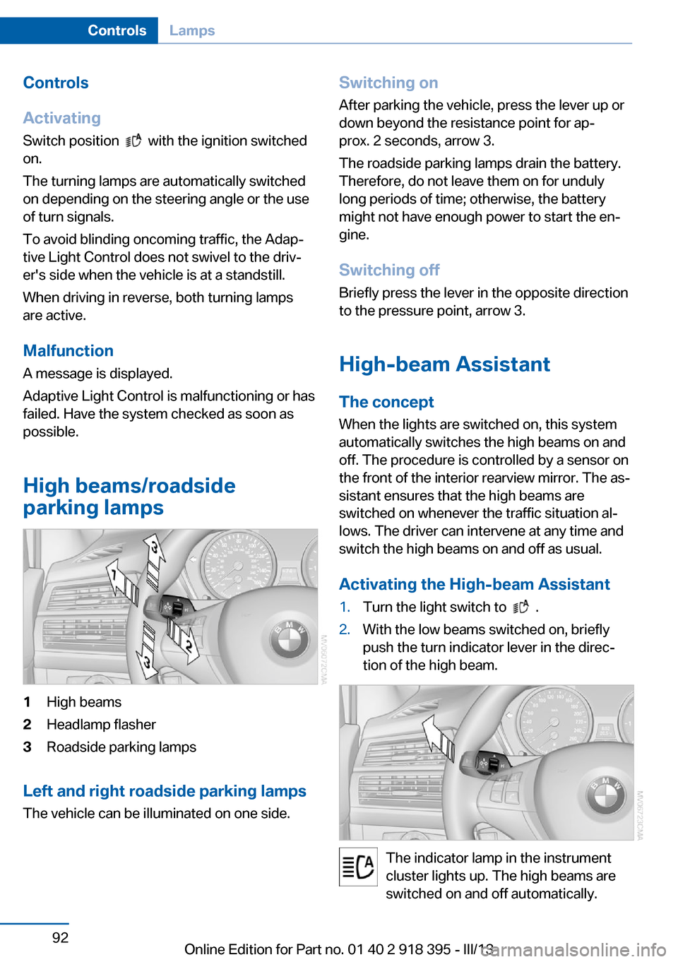
1High beams2Headlamp flasher3Roadside parking lamps
Left and right roadside parking lamps
The vehicle can be illuminated on one side.
Switching onAfter parking the vehicle, press the lever up ordown beyond the resistance point for ap‐
prox. 2 seconds, arrow 3.
The roadside parking lamps drain the battery.
Therefore, do not leave them on for unduly
long periods of time; otherwise, the battery
might not have enough power to start the en‐
gine.
Switching off
Briefly press the lever in the opposite direction
to the pressure point, arrow 3.
High-beam Assistant
The concept When the lights are switched on, this systemautomatically switches the high beams on and
off. The procedure is controlled by a sensor on
the front of the interior rearview mirror. The as‐
sistant ensures that the high beams are
switched on whenever the traffic situation al‐
lows. The driver can intervene at any time and
switch the high beams on and off as usual.
Activating the High-beam Assistant1.Turn the light switch to .2.With the low beams switched on, briefly
push the turn indicator lever in the direc‐
tion of the high beam.
The indicator lamp in the instrument
cluster lights up. The high beams are
switched on and off automatically.
Seite 92ControlsLamps92
Online Edition for Part no. 01 40 2 918 395 - III/13
Page 102 of 345
Check the tire inflation pressure and reset the
system.
Malfunction The small warning lamp flashes inyellow and then lights up continu‐
ously; the larger warning lamp comes
on in yellow. On the Control Display,
the tires are shown in gray and a message ap‐
pears. No flat tire can be detected.
Display in the following situations:▷If a wheel without TPM electronics is fitted,
for instance a compact wheel: have the
service center check it if necessary.▷Malfunction: have the system checked by
your service center.▷TPM could not be fully reset. Reset the
system again.▷Disturbance by systems or devices with
the same radio frequency: after leaving the
area of the disturbance, the system auto‐
matically becomes active again.
Declaration according to NHTSA/
FMVSS 138 Tire Pressure Monitoring
Systems
Each tire, including the spare (if provided)
should be checked monthly when cold and in‐
flated to the inflation pressure recommended
by the vehicle manufacturer on the vehicle
placard or tire inflation pressure label (If your
vehicle has tires of a different size than the size
indicated on the vehicle placard or tire inflation
pressure label, you should determine the
proper tire inflation pressure for those tires.).
As an added safety feature, your vehicle has
been equipped with a tire pressure monitoring
system (TPMS) that illuminates a low tire pres‐
sure telltale when one or more of your tires is
significantly under-inflated. Accordingly, when
the low tire pressure telltale illuminates, you
should stop and check your tires as soon as
possible, and inflate them to the proper pres‐
sure. Driving on a significantly under-inflated
tire causes the tire to overheat and can lead to
tire failure. Under-inflation also reduces fuel ef‐
ficiency and tire tread life, and may affect the
vehicle's handling and stopping ability.
Please note that the TPMS is not a substitute
for proper tire maintenance, and it is the driv‐
er's responsibility to maintain correct tire pres‐
sure, even if under-inflation has not reached
the level to trigger illumination of the TPMS
low tire pressure telltale.
Your vehicle has also been equipped with a
TPMS malfunction indicator to indicate when
the system is not operating properly. The
TPMS malfunction indicator is combined with
the low tire pressure telltale. When the system
detects a malfunction, the telltale will flash for
approximately one minute and then remain
continuously illuminated. This sequence will
continue upon subsequent vehicle startups as
long as the malfunction exists. When the mal‐
function indicator is illuminated, the system
may not be able to detect or signal low tire
pressure as intended. TPMS malfunctions may
occur for a variety of reasons, including the in‐
stallation of replacement or alternate tires or
wheels on the vehicle that prevent the TPMS
from functioning properly. Always check the
TPMS malfunction telltale after replacing one
or more tires or wheels on your vehicle to en‐
sure that the replacement or alternate tires and
wheels allow the TPMS to continue to function
properly.
Lane departure warning
The concept This system issues a warning at speeds above
approx. 40 mph/65 km/h if the vehicle is about
to leave the lane on roads with lane markings.
The steering wheel begins vibrating lightly.
The time when the warning is issued may vary
with the current driving situation.
The system does not issue a warning if the
turn signal is set before leaving the lane.Seite 102ControlsSafety102
Online Edition for Part no. 01 40 2 918 395 - III/13
Page 103 of 345
Switching on/off
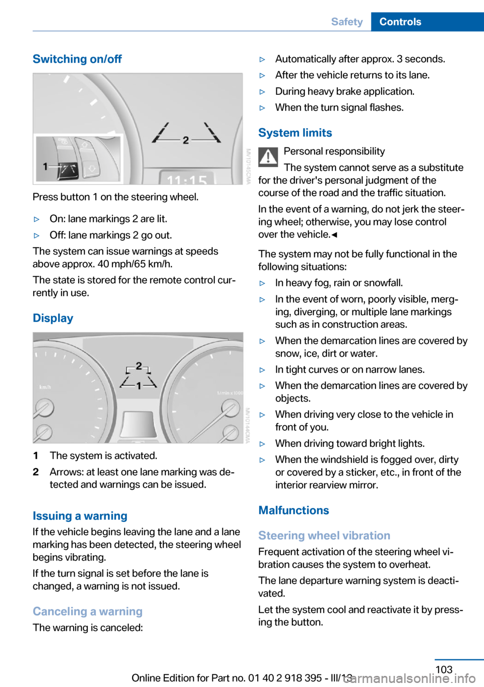
Press button 1 on the steering wheel.
▷On: lane markings 2 are lit.▷Off: lane markings 2 go out.
The system can issue warnings at speeds
above approx. 40 mph/65 km/h.
The state is stored for the remote control cur‐
rently in use.
Display
1The system is activated.2Arrows: at least one lane marking was de‐
tected and warnings can be issued.
Issuing a warning
If the vehicle begins leaving the lane and a lane
marking has been detected, the steering wheel
begins vibrating.
If the turn signal is set before the lane is
changed, a warning is not issued.
Canceling a warning The warning is canceled:
▷Automatically after approx. 3 seconds.▷After the vehicle returns to its lane.▷During heavy brake application.▷When the turn signal flashes.
System limits
Personal responsibility
The system cannot serve as a substitute
for the driver's personal judgment of the
course of the road and the traffic situation.
In the event of a warning, do not jerk the steer‐
ing wheel; otherwise, you may lose control
over the vehicle.◀
The system may not be fully functional in the
following situations:
▷In heavy fog, rain or snowfall.▷In the event of worn, poorly visible, merg‐
ing, diverging, or multiple lane markings
such as in construction areas.▷When the demarcation lines are covered by
snow, ice, dirt or water.▷In tight curves or on narrow lanes.▷When the demarcation lines are covered by
objects.▷When driving very close to the vehicle in
front of you.▷When driving toward bright lights.▷When the windshield is fogged over, dirty
or covered by a sticker, etc., in front of the
interior rearview mirror.
Malfunctions
Steering wheel vibration
Frequent activation of the steering wheel vi‐
bration causes the system to overheat.
The lane departure warning system is deacti‐
vated.
Let the system cool and reactivate it by press‐
ing the button.
Seite 103SafetyControls103
Online Edition for Part no. 01 40 2 918 395 - III/13
Page 191 of 345
Multi-channel playback,
surround
Choose between stereo and multi-channel
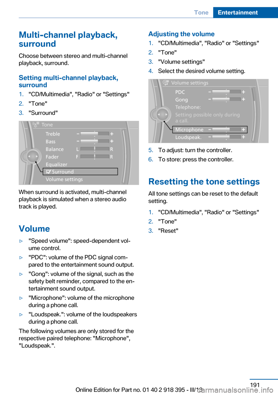
playback, surround.
Setting multi-channel playback,
surround1."CD/Multimedia", "Radio" or "Settings"2."Tone"3."Surround"
When surround is activated, multi-channel
playback is simulated when a stereo audio
track is played.
Volume
▷"Speed volume": speed-dependent vol‐
ume control.▷"PDC": volume of the PDC signal com‐
pared to the entertainment sound output.▷"Gong": volume of the signal, such as the
safety belt reminder, compared to the en‐
tertainment sound output.▷"Microphone": volume of the microphone
during a phone call.▷"Loudspeak.": volume of the loudspeakers
during a phone call.
The following volumes are only stored for the
respective paired telephone: "Microphone",
"Loudspeak.".
Adjusting the volume1."CD/Multimedia", "Radio" or "Settings"2."Tone"3."Volume settings"4.Select the desired volume setting.5.To adjust: turn the controller.6.To store: press the controller.
Resetting the tone settings
All tone settings can be reset to the default
setting.
1."CD/Multimedia", "Radio" or "Settings"2."Tone"3."Reset"Seite 191ToneEntertainment191
Online Edition for Part no. 01 40 2 918 395 - III/13
Page 193 of 345
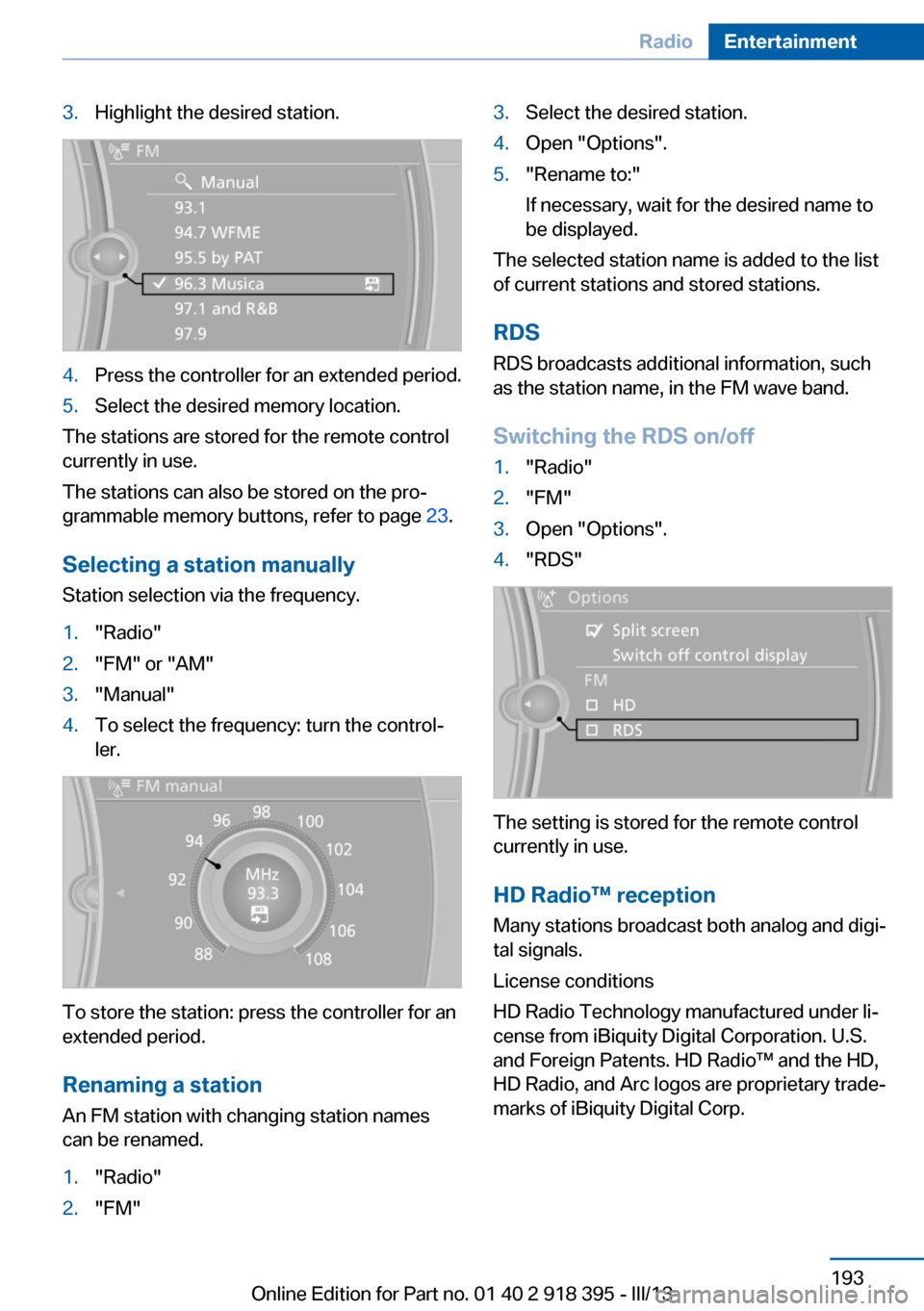
3.Highlight the desired station.4.Press the controller for an extended period.5.Select the desired memory location.
The stations are stored for the remote control
currently in use.
The stations can also be stored on the pro‐
grammable memory buttons, refer to page 23.
Selecting a station manually
Station selection via the frequency.
1."Radio"2."FM" or "AM"3."Manual"4.To select the frequency: turn the control‐
ler.
To store the station: press the controller for an
extended period.
Renaming a station An FM station with changing station names
can be renamed.
1."Radio"2."FM"3.Select the desired station.4.Open "Options".5."Rename to:"
If necessary, wait for the desired name to
be displayed.
The selected station name is added to the list
of current stations and stored stations.
RDSRDS broadcasts additional information, such
as the station name, in the FM wave band.
Switching the RDS on/off
1."Radio"2."FM"3.Open "Options".4."RDS"
The setting is stored for the remote control
currently in use.
HD Radio™ reception
Many stations broadcast both analog and digi‐
tal signals.
License conditions
HD Radio Technology manufactured under li‐
cense from iBiquity Digital Corporation. U.S.
and Foreign Patents. HD Radio™ and the HD,
HD Radio, and Arc logos are proprietary trade‐
marks of iBiquity Digital Corp.
Seite 193RadioEntertainment193
Online Edition for Part no. 01 40 2 918 395 - III/13
Page 196 of 345
Via direct channel entry1."Radio"2."Satellite radio"3. "Set channel"4.Turn the controller until the desired chan‐
nel is reached and press the controller.
Storing a channel
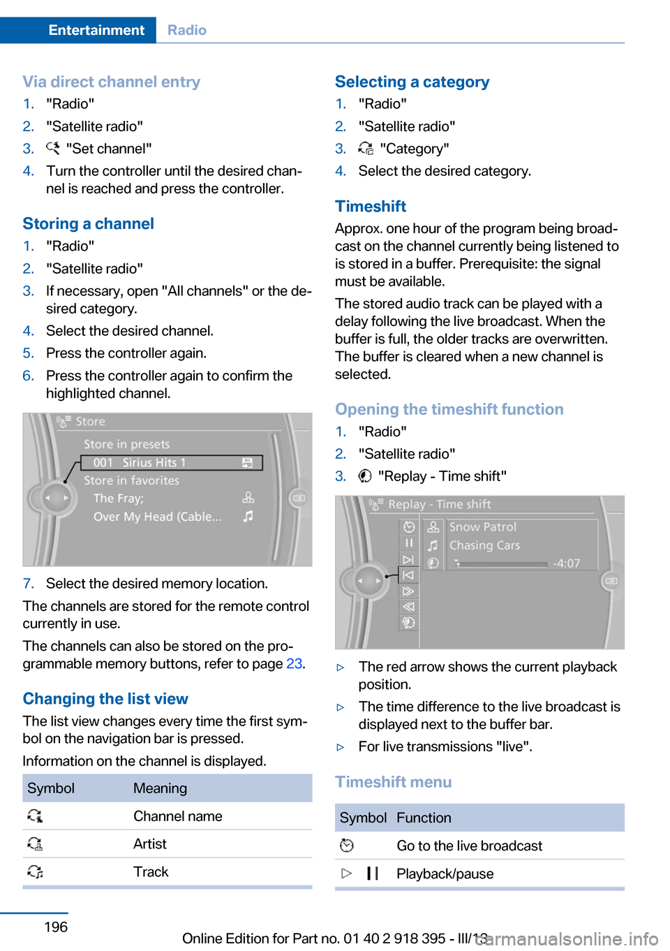
1."Radio"2."Satellite radio"3.If necessary, open "All channels" or the de‐
sired category.4.Select the desired channel.5.Press the controller again.6.Press the controller again to confirm the
highlighted channel.7.Select the desired memory location.
The channels are stored for the remote control
currently in use.
The channels can also be stored on the pro‐
grammable memory buttons, refer to page 23.
Changing the list view
The list view changes every time the first sym‐
bol on the navigation bar is pressed.
Information on the channel is displayed.
SymbolMeaning Channel name Artist TrackSelecting a category1."Radio"2."Satellite radio"3. "Category"4.Select the desired category.
Timeshift
Approx. one hour of the program being broad‐
cast on the channel currently being listened to
is stored in a buffer. Prerequisite: the signal
must be available.
The stored audio track can be played with a
delay following the live broadcast. When the
buffer is full, the older tracks are overwritten.
The buffer is cleared when a new channel is
selected.
Opening the timeshift function
1."Radio"2."Satellite radio"3. "Replay - Time shift"▷The red arrow shows the current playback
position.▷The time difference to the live broadcast is
displayed next to the buffer bar.▷For live transmissions "live".
Timeshift menu
SymbolFunction Go to the live broadcast Playback/pauseSeite 196EntertainmentRadio196
Online Edition for Part no. 01 40 2 918 395 - III/13
Page 240 of 345
nected mobile phone from the vehicle and
pair and connect only one mobile phone.
The mobile phone no longer reacts.
▷Switch the mobile phone off and on again.▷Is the ambient temperature too high or
low? Do not expose the mobile phone to
extreme environmental conditions.
The telephone functions are not available.
▷Is the mobile phone paired as an additional
telephone and is the additional telephone
function deactivated? Activate the func‐
tion.▷Is an outgoing call not possible? Connect
the mobile phone as a telephone.
No phone book entries or only some phone
book entries are displayed, or they are incom‐
plete.
▷Transmission of the phone book entries is
not yet complete.▷It is possible that only the phone book en‐
tries of the mobile phone or the SIM card
are transmitted.▷It may not be possible to display phone
book entries with special characters.▷The number of phone book entries to be
stored is too high.▷Is the data volume of the contact too large,
e. g., due to stored information such as
notes? Reduce the data volume of the con‐
tact.▷Is the mobile phone connected as an audio
source or additional telephone? The mo‐
bile phone must be connected as a tele‐
phone.
The phone connection quality is poor.
▷The strength of the Bluetooth signal on the
mobile phone can be adjusted, depending
on the mobile phone.▷Insert the mobile phone into the snap-in
adapter or place it in the area of the center
console.▷Adjust the volume of the microphone and
loudspeakers separately.
If all points in this list have been checked and
the required function is still not available, con‐
tact Customer Relations or the service center.
Controls
Adjusting the volume
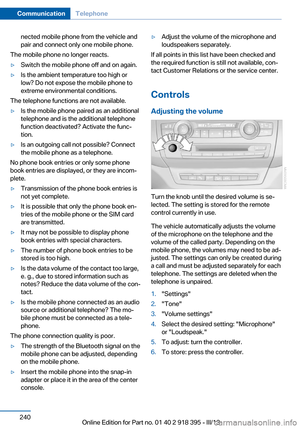
Turn the knob until the desired volume is se‐
lected. The setting is stored for the remote
control currently in use.
The vehicle automatically adjusts the volume
of the microphone on the telephone and the
volume of the called party. Depending on the
mobile phone, the volumes may need to be ad‐
justed. The settings can only be created during
a call and must be adjusted separately for each
telephone. The settings are deleted when the
telephone is unpaired.
1."Settings"2."Tone"3."Volume settings"4.Select the desired setting: "Microphone"
or "Loudspeak."5.To adjust: turn the controller.6.To store: press the controller.Seite 240CommunicationTelephone240
Online Edition for Part no. 01 40 2 918 395 - III/13
Page 242 of 345
If a second call comes in during an ongoing
call, a call waiting signal is sounded.
"Accept"
The call is accepted and the existing call is put
on hold.
Establishing a second call
Establish an additional call during an active
call.
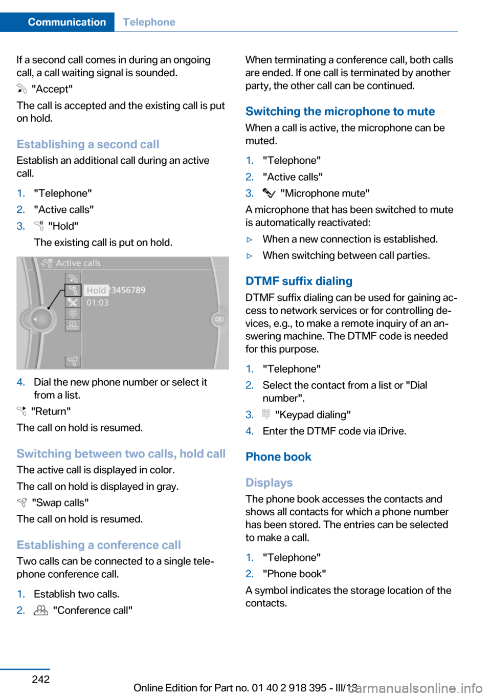
1."Telephone"2."Active calls"3. "Hold"
The existing call is put on hold.4.Dial the new phone number or select it
from a list.
"Return"
The call on hold is resumed.
Switching between two calls, hold call The active call is displayed in color.
The call on hold is displayed in gray.
"Swap calls"
The call on hold is resumed.
Establishing a conference call Two calls can be connected to a single tele‐
phone conference call.
1.Establish two calls.2. "Conference call"When terminating a conference call, both calls
are ended. If one call is terminated by another
party, the other call can be continued.
Switching the microphone to mute When a call is active, the microphone can be
muted.1."Telephone"2."Active calls"3. "Microphone mute"
A microphone that has been switched to mute
is automatically reactivated:
▷When a new connection is established.▷When switching between call parties.
DTMF suffix dialing
DTMF suffix dialing can be used for gaining ac‐
cess to network services or for controlling de‐
vices, e.g., to make a remote inquiry of an an‐
swering machine. The DTMF code is needed
for this purpose.
1."Telephone"2.Select the contact from a list or "Dial
number".3. "Keypad dialing"4.Enter the DTMF code via iDrive.
Phone book
Displays The phone book accesses the contacts and
shows all contacts for which a phone number
has been stored. The entries can be selected
to make a call.
1."Telephone"2."Phone book"
A symbol indicates the storage location of the
contacts.
Seite 242CommunicationTelephone242
Online Edition for Part no. 01 40 2 918 395 - III/13
Page 297 of 345
Parking lamps, roadside parking
lamps, daytime running lights
These lamps are made using LED technology.
Contact your service center in the event of a
malfunction.
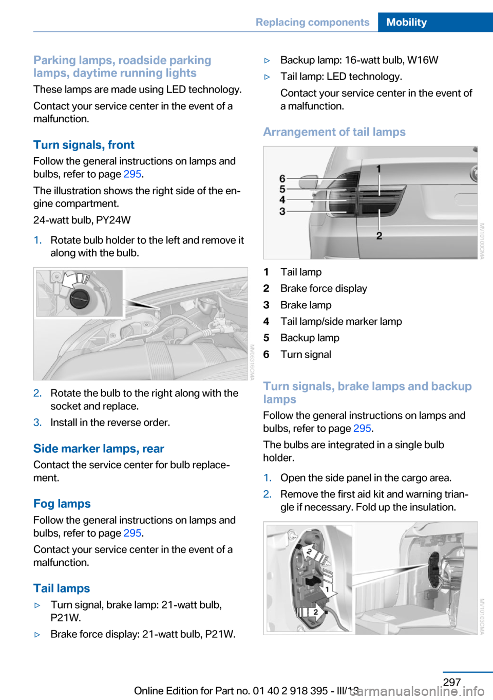
Turn signals, frontFollow the general instructions on lamps and
bulbs, refer to page 295.
The illustration shows the right side of the en‐
gine compartment.
24-watt bulb, PY24W1.Rotate bulb holder to the left and remove it
along with the bulb.2.Rotate the bulb to the right along with the
socket and replace.3.Install in the reverse order.
Side marker lamps, rear
Contact the service center for bulb replace‐
ment.
Fog lamps Follow the general instructions on lamps and
bulbs, refer to page 295.
Contact your service center in the event of a
malfunction.
Tail lamps
▷Turn signal, brake lamp: 21-watt bulb,
P21W.▷Brake force display: 21-watt bulb, P21W.▷Backup lamp: 16-watt bulb, W16W▷Tail lamp: LED technology.
Contact your service center in the event of
a malfunction.
Arrangement of tail lamps
1Tail lamp2Brake force display3Brake lamp4Tail lamp/side marker lamp5Backup lamp6Turn signal
Turn signals, brake lamps and backup
lamps
Follow the general instructions on lamps and
bulbs, refer to page 295.
The bulbs are integrated in a single bulb holder.
1.Open the side panel in the cargo area.2.Remove the first aid kit and warning trian‐
gle if necessary. Fold up the insulation.Seite 297Replacing componentsMobility297
Online Edition for Part no. 01 40 2 918 395 - III/13
Page 300 of 345
▷Daytime running lights.▷Side marker lights.
Contact your service center in the event of a
malfunction.
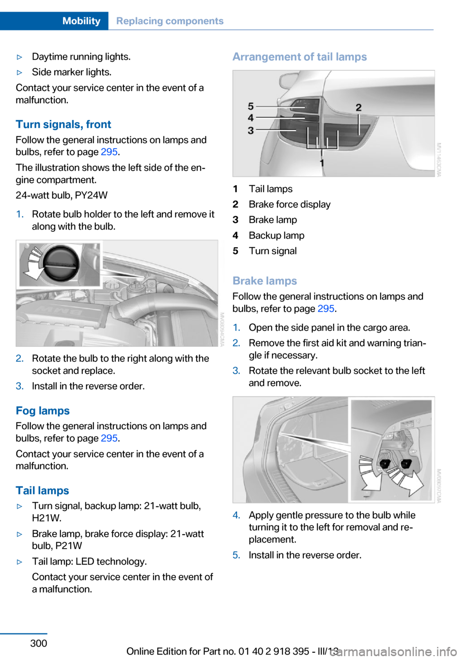
Turn signals, frontFollow the general instructions on lamps and
bulbs, refer to page 295.
The illustration shows the left side of the en‐
gine compartment.
24-watt bulb, PY24W
1.Rotate bulb holder to the left and remove it
along with the bulb.2.Rotate the bulb to the right along with the
socket and replace.3.Install in the reverse order.
Fog lamps
Follow the general instructions on lamps and
bulbs, refer to page 295.
Contact your service center in the event of a
malfunction.
Tail lamps
▷Turn signal, backup lamp: 21-watt bulb,
H21W.▷Brake lamp, brake force display: 21-watt
bulb, P21W▷Tail lamp: LED technology.
Contact your service center in the event of
a malfunction.Arrangement of tail lamps1Tail lamps2Brake force display3Brake lamp4Backup lamp5Turn signal
Brake lamps
Follow the general instructions on lamps and
bulbs, refer to page 295.
1.Open the side panel in the cargo area.2.Remove the first aid kit and warning trian‐
gle if necessary.3.Rotate the relevant bulb socket to the left
and remove.4.Apply gentle pressure to the bulb while
turning it to the left for removal and re‐
placement.5.Install in the reverse order.Seite 300MobilityReplacing components300
Online Edition for Part no. 01 40 2 918 395 - III/13