Side view BMW X5 2015 F15 User Guide
[x] Cancel search | Manufacturer: BMW, Model Year: 2015, Model line: X5, Model: BMW X5 2015 F15Pages: 275, PDF Size: 6.46 MB
Page 97 of 275
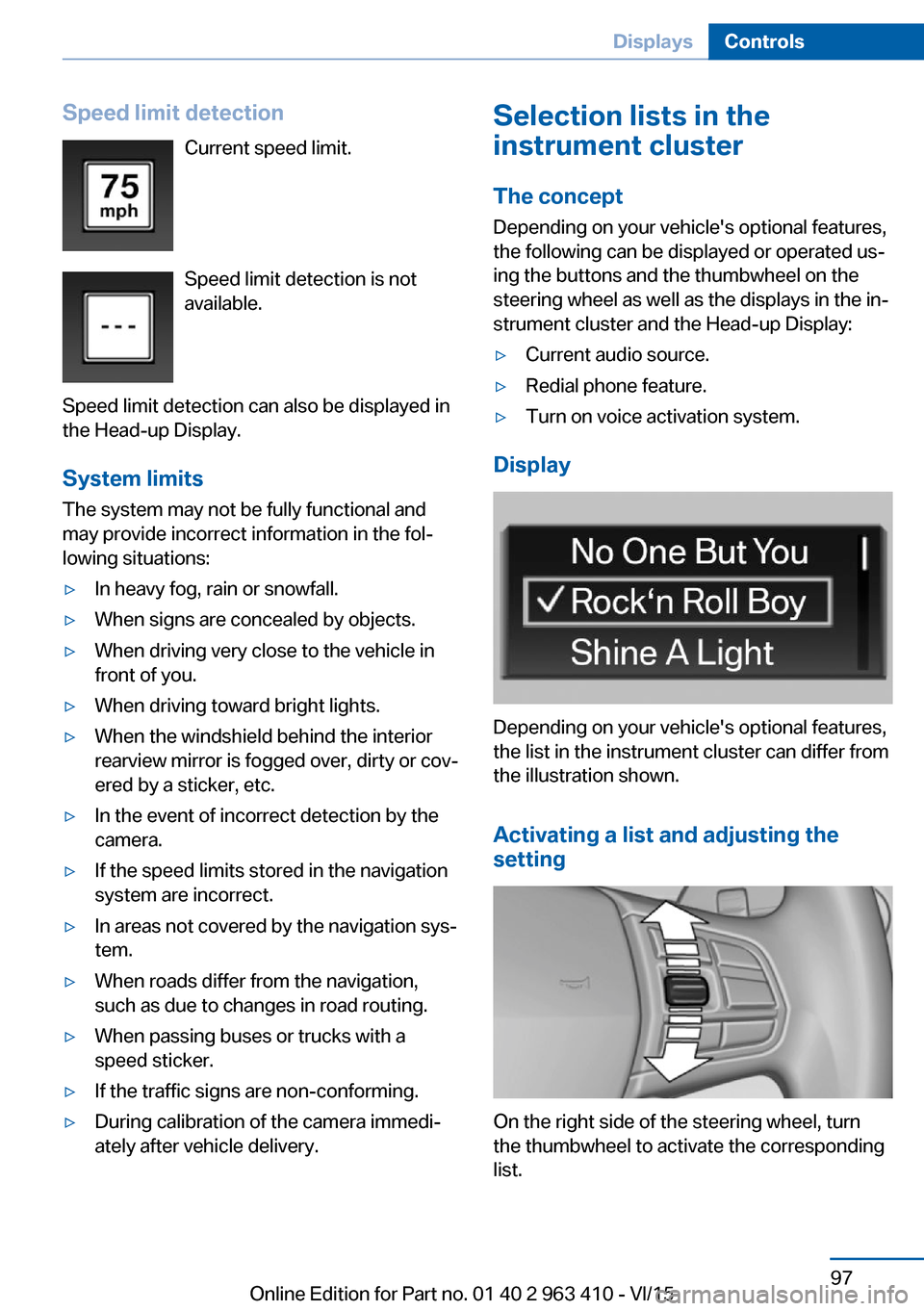
Speed limit detectionCurrent speed limit.
Speed limit detection is not
available.
Speed limit detection can also be displayed in
the Head-up Display.
System limits
The system may not be fully functional and
may provide incorrect information in the fol‐
lowing situations:▷In heavy fog, rain or snowfall.▷When signs are concealed by objects.▷When driving very close to the vehicle in
front of you.▷When driving toward bright lights.▷When the windshield behind the interior
rearview mirror is fogged over, dirty or cov‐
ered by a sticker, etc.▷In the event of incorrect detection by the
camera.▷If the speed limits stored in the navigation
system are incorrect.▷In areas not covered by the navigation sys‐
tem.▷When roads differ from the navigation,
such as due to changes in road routing.▷When passing buses or trucks with a
speed sticker.▷If the traffic signs are non-conforming.▷During calibration of the camera immedi‐
ately after vehicle delivery.Selection lists in the
instrument cluster
The concept Depending on your vehicle's optional features,
the following can be displayed or operated us‐
ing the buttons and the thumbwheel on the
steering wheel as well as the displays in the in‐
strument cluster and the Head-up Display:▷Current audio source.▷Redial phone feature.▷Turn on voice activation system.
Display
Depending on your vehicle's optional features,
the list in the instrument cluster can differ from
the illustration shown.
Activating a list and adjusting the
setting
On the right side of the steering wheel, turn
the thumbwheel to activate the corresponding
list.
Seite 97DisplaysControls97
Online Edition for Part no. 01 40 2 963 410 - VI/15
Page 104 of 275
LightsVehicle features and optionsThis chapter describes all standard, country-
specific and optional features offered with the
series. It also describes features that are not
necessarily available in your car, e. g., due to
the selected options or country versions. This
also applies to safety-related functions and
systems. The respectively applicable country
provisions must be observed when using the
respective features and systems.
Overview Switches in the vehicle
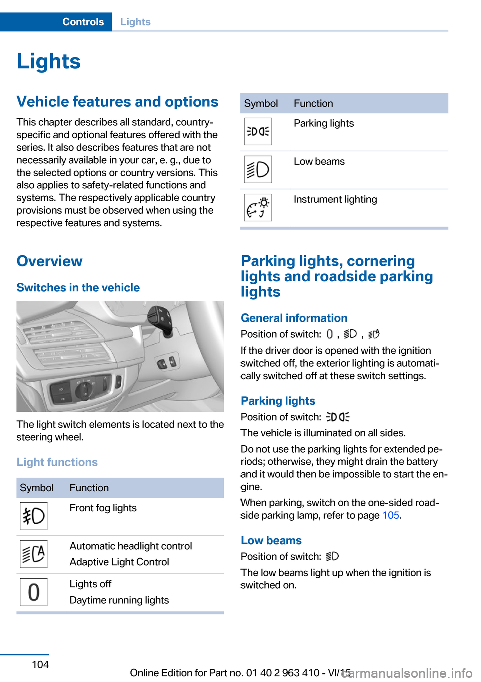
The light switch elements is located next to the
steering wheel.
Light functions
SymbolFunctionFront fog lightsAutomatic headlight control
Adaptive Light ControlLights off
Daytime running lightsSymbolFunctionParking lightsLow beamsInstrument lighting
Parking lights, cornering
lights and roadside parking
lights
General information Position of switch:
, ,
If the driver door is opened with the ignition
switched off, the exterior lighting is automati‐
cally switched off at these switch settings.
Parking lights
Position of switch:
The vehicle is illuminated on all sides.
Do not use the parking lights for extended pe‐
riods; otherwise, they might drain the battery
and it would then be impossible to start the en‐
gine.
When parking, switch on the one-sided road‐
side parking lamp, refer to page 105.
Low beams Position of switch:
The low beams light up when the ignition is
switched on.
Seite 104ControlsLights104
Online Edition for Part no. 01 40 2 963 410 - VI/15
Page 106 of 275
E. g. the sensors are unable to detect fog or
hazy weather. To avoid safety risks under
these conditions, you should always switch on
the lights manually.
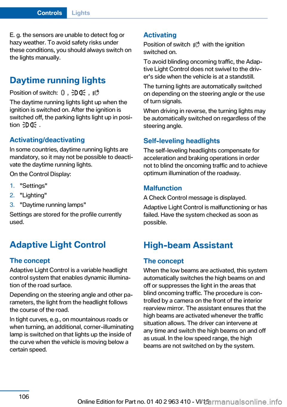
Daytime running lights Position of switch:
, ,
The daytime running lights light up when the
ignition is switched on. After the ignition is
switched off, the parking lights light up in posi‐
tion
.
Activating/deactivating In some countries, daytime running lights are
mandatory, so it may not be possible to deacti‐
vate the daytime running lights.
On the Control Display:
1."Settings"2."Lighting"3."Daytime running lamps"
Settings are stored for the profile currently
used.
Adaptive Light Control
The concept Adaptive Light Control is a variable headlight
control system that enables dynamic illumina‐
tion of the road surface.
Depending on the steering angle and other pa‐
rameters, the light from the headlight follows
the course of the road.
In tight curves, e.g., on mountainous roads or
when turning, an additional, corner-illuminating
lamp is switched on that lights up the inside of
the curve when the vehicle is moving below a
certain speed.
Activating
Position of switch
with the ignition
switched on.
To avoid blinding oncoming traffic, the Adap‐
tive Light Control does not swivel to the driv‐
er's side when the vehicle is at a standstill.
The turning lights are automatically switched
on depending on the steering angle or the use
of turn signals.
When driving in reverse, the turning lights may
be automatically switched on regardless of the
steering angle.
Self-leveling headlights The self-leveling headlights compensate for
acceleration and braking operations in order
not to blind the oncoming traffic and to achieve
optimum illumination of the roadway.
Malfunction A Check Control message is displayed.
Adaptive Light Control is malfunctioning or has
failed. Have the system checked as soon as
possible.
High-beam Assistant
The concept When the low beams are activated, this system
automatically switches the high beams on and
off or suppresses the light in the areas that
blind oncoming traffic. The procedure is con‐
trolled by a camera on the front of the interior
rearview mirror. The assistant ensures that the
high beams are activated whenever the traffic
situation allows. The driver can intervene at
any time and switch the high beams on and off
as usual. In the low speed range, the high
beams are not switched on by the system.
Seite 106ControlsLights106
Online Edition for Part no. 01 40 2 963 410 - VI/15
Page 124 of 275
Warning with braking function
Display
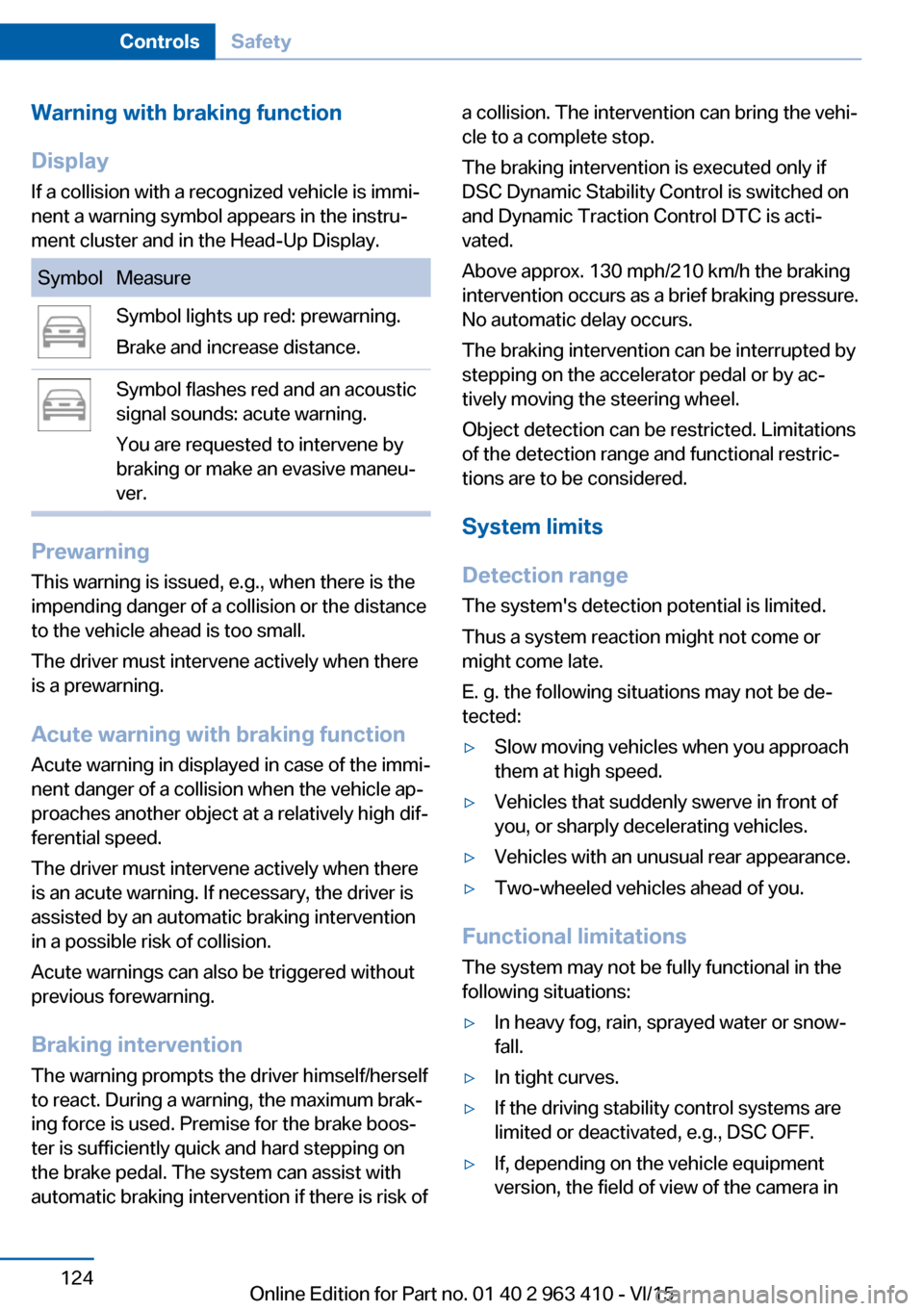
If a collision with a recognized vehicle is immi‐
nent a warning symbol appears in the instru‐
ment cluster and in the Head-Up Display.SymbolMeasureSymbol lights up red: prewarning.
Brake and increase distance.Symbol flashes red and an acoustic
signal sounds: acute warning.
You are requested to intervene by
braking or make an evasive maneu‐
ver.
Prewarning
This warning is issued, e.g., when there is the
impending danger of a collision or the distance
to the vehicle ahead is too small.
The driver must intervene actively when there
is a prewarning.
Acute warning with braking function
Acute warning in displayed in case of the immi‐
nent danger of a collision when the vehicle ap‐
proaches another object at a relatively high dif‐
ferential speed.
The driver must intervene actively when there
is an acute warning. If necessary, the driver is
assisted by an automatic braking intervention
in a possible risk of collision.
Acute warnings can also be triggered without
previous forewarning.
Braking intervention
The warning prompts the driver himself/herself
to react. During a warning, the maximum brak‐
ing force is used. Premise for the brake boos‐
ter is sufficiently quick and hard stepping on
the brake pedal. The system can assist with automatic braking intervention if there is risk of
a collision. The intervention can bring the vehi‐
cle to a complete stop.
The braking intervention is executed only if
DSC Dynamic Stability Control is switched on
and Dynamic Traction Control DTC is acti‐
vated.
Above approx. 130 mph/210 km/h the braking
intervention occurs as a brief braking pressure.
No automatic delay occurs.
The braking intervention can be interrupted by
stepping on the accelerator pedal or by ac‐
tively moving the steering wheel.
Object detection can be restricted. Limitations
of the detection range and functional restric‐
tions are to be considered.
System limits
Detection range
The system's detection potential is limited.
Thus a system reaction might not come or
might come late.
E. g. the following situations may not be de‐
tected:▷Slow moving vehicles when you approach
them at high speed.▷Vehicles that suddenly swerve in front of
you, or sharply decelerating vehicles.▷Vehicles with an unusual rear appearance.▷Two-wheeled vehicles ahead of you.
Functional limitations
The system may not be fully functional in the
following situations:
▷In heavy fog, rain, sprayed water or snow‐
fall.▷In tight curves.▷If the driving stability control systems are
limited or deactivated, e.g., DSC OFF.▷If, depending on the vehicle equipment
version, the field of view of the camera inSeite 124ControlsSafety124
Online Edition for Part no. 01 40 2 963 410 - VI/15
Page 127 of 275
Braking intervention
The warning prompts the driver himself/herself
to react. During a warning, the maximum brak‐
ing force is used. Premise for the brake boos‐
ter is sufficiently quick and hard stepping on
the brake pedal. The system can assist with
some braking intervention if there is risk of a
collision. At low speeds vehicles may thus
come to a complete stop.
The braking intervention is executed only if
DSC Dynamic Stability Control is switched on
and Dynamic Traction Control DTC is acti‐
vated.
The braking intervention can be interrupted by
stepping on the accelerator pedal or by ac‐
tively moving the steering wheel.
Object detection can be restricted. Limitations
of the detection range and functional restric‐
tions are to be considered.
System limits
Detection range
The detection potential of the camera is lim‐
ited.
Thus a warning might not be issued or be is‐
sued late.
E. g. the following situations may not be de‐
tected:▷Partially covered pedestrians.▷Pedestrians that are not detected as such
because of the viewing angle or contour.▷Pedestrians outside of the detection range.▷Pedestrians having a body size less than
32 in/80 cm.
Functional limitations
The system may not be fully functional or may
not be available in the following situations:
The system may not be fully functional in the
following situations:
▷In heavy fog, rain, sprayed water or snow‐
fall.▷In tight curves.▷If the driving stability control systems are
deactivated, e.g. DSC OFF.▷If the field of view of the camera or the front
windshield are dirty or covered.▷Up to 10 seconds after the start of the en‐
gine, via the Start/Stop button.▷During calibration of the camera immedi‐
ately after vehicle delivery.▷If there are constant blinding effects be‐
cause of oncoming light, e. g., from the sun
low in the sky.▷When it is dark outside.
Night Vision with Pedestrian
and Animal Detection
The concept Night Vision with pedestrian and animal detec‐
tion is a night vision system.
An infrared camera scans the area in front of
the vehicle and issues a warning if it detects
pedestrians and animals on the street. Warm
objects that are similar in shape to human be‐
ings or animals are detected by the system. If necessary, the heat image can be displayed on
the Control Display.
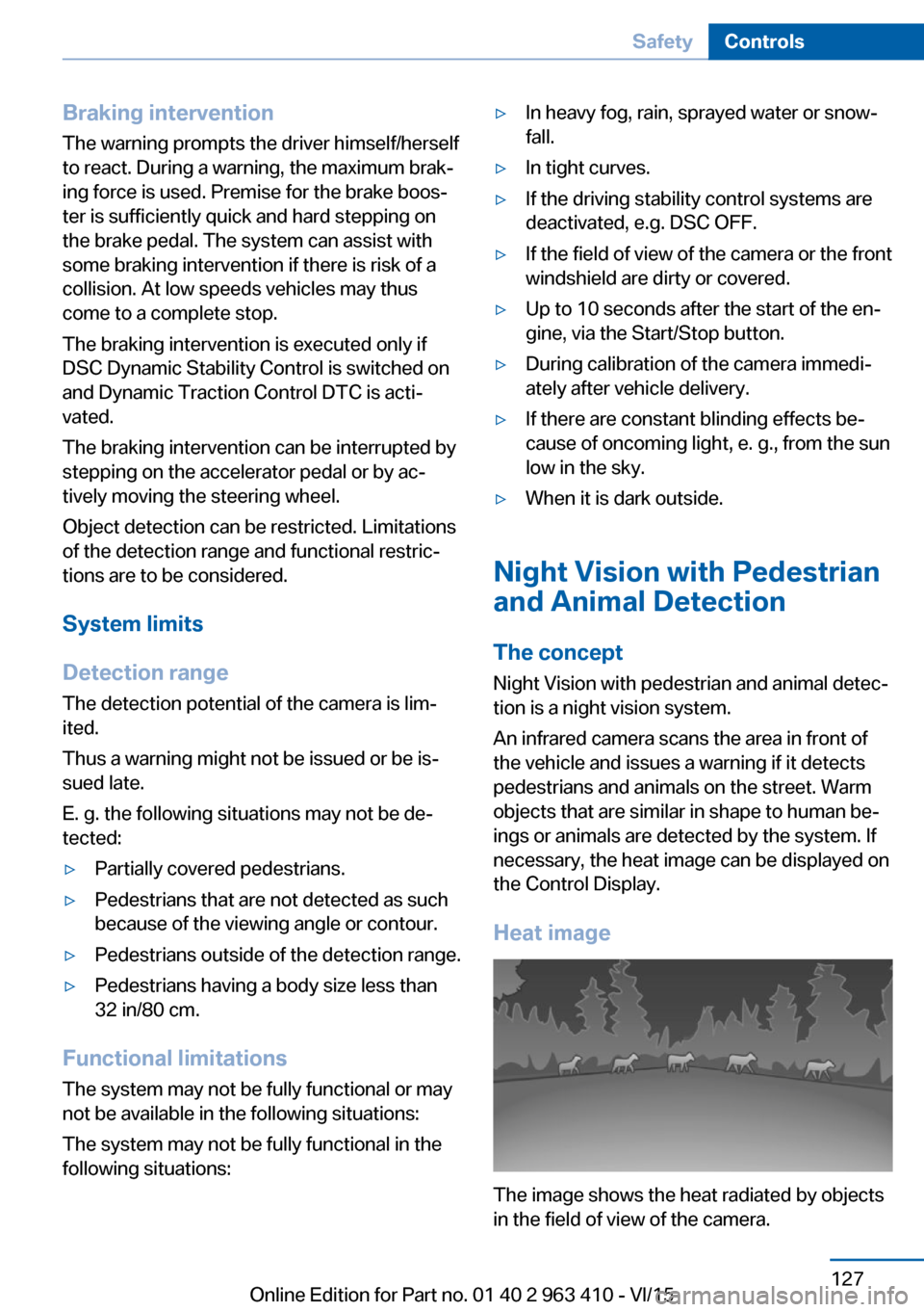
Heat image
The image shows the heat radiated by objects
in the field of view of the camera.
Seite 127SafetyControls127
Online Edition for Part no. 01 40 2 963 410 - VI/15
Page 128 of 275
Warm objects have a light appearance and
cold objects a dark appearance.
The ability to detect an object depends on the
temperature difference between the object
and the background and on the level of heat
radiation emitted by the object. Objects that
are similar in temperature to the environment
or that radiate very little heat are difficult to de‐
tect.
For safety reasons, when driving at speeds
above approx. 3 mph/5 km/h and in low ambi‐
ent light, the image is only displayed when the
low beams are activated.
A still image is displayed at regular intervals for
a fraction of a second.
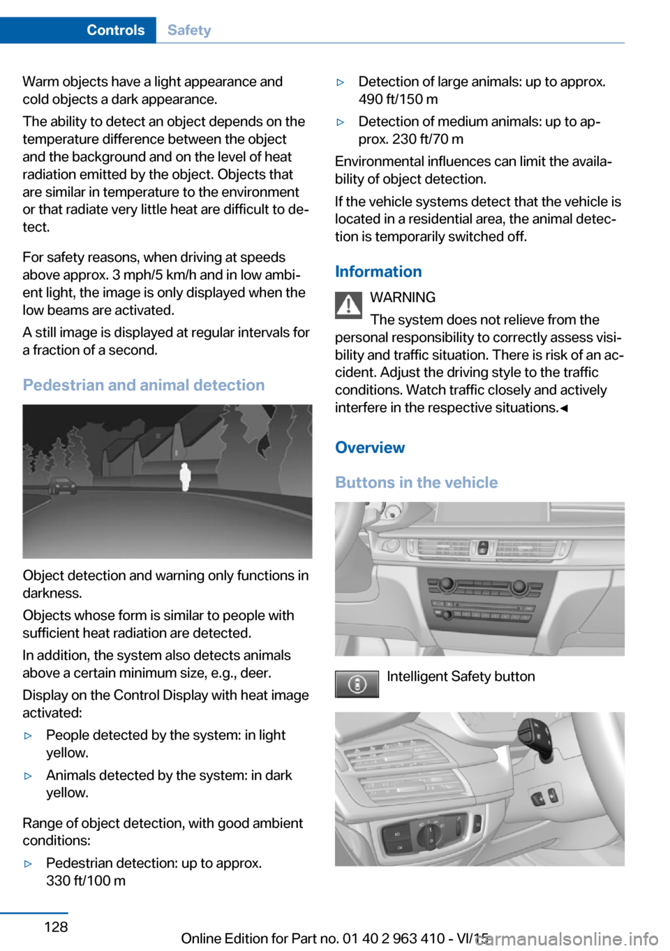
Pedestrian and animal detection
Object detection and warning only functions in
darkness.
Objects whose form is similar to people with
sufficient heat radiation are detected.
In addition, the system also detects animals
above a certain minimum size, e.g., deer.
Display on the Control Display with heat image
activated:
▷People detected by the system: in light
yellow.▷Animals detected by the system: in dark
yellow.
Range of object detection, with good ambient
conditions:
▷Pedestrian detection: up to approx.
330 ft/100 m▷Detection of large animals: up to approx.
490 ft/150 m▷Detection of medium animals: up to ap‐
prox. 230 ft/70 m
Environmental influences can limit the availa‐
bility of object detection.
If the vehicle systems detect that the vehicle is
located in a residential area, the animal detec‐
tion is temporarily switched off.
Information WARNING
The system does not relieve from the
personal responsibility to correctly assess visi‐
bility and traffic situation. There is risk of an ac‐
cident. Adjust the driving style to the traffic
conditions. Watch traffic closely and actively
interfere in the respective situations.◀
Overview
Buttons in the vehicle
Intelligent Safety button
Seite 128ControlsSafety128
Online Edition for Part no. 01 40 2 963 410 - VI/15
Page 138 of 275
curve to the wheel on the outside of the curve
or vice-versa.
To increase the maneuverability, the rear
wheel on the outside of the curve is acceler‐
ated when the driving style is correspondingly
sporty.
The steering responds directly; simultane‐
ously, the understeering tendency of the four-
wheel drive is reduced.
With the oversteering tendency, the system
exerts a stabilizing effect by accelerating the
rear wheel on the inside of the curve.
The system noticeably improves the traction
and simultaneously increases the driving
safety, especially on road surfaces having fluc‐
tuating coefficients of friction.
DSC Dynamic Stability
Control
The concept
DSC prevents traction loss in the power
wheels when driving off and accelerating.
DSC also recognizes unstable vehicle condi‐
tions such as fishtailing or nose-diving. Within the physical limits DSC helps to keep the vehi‐
cle on a steady course by reducing engine
speed and by applying brakes to the individual
wheels.
Information
Adapt your driving style to the situation, for an
appropriate driving style is always the respon‐
sibility of the driver.
The laws of physics cannot be repealed, not
even with DSC.
Therefore, do not reduce the additional safety
margin by driving in a risky manner.
WARNING
When driving with roof load, e.g. with
roof-mounted luggage rack, driving safety may
not be ensured in driving-critical situations dueto the elevated center of gravity. There is risk
of accidents or risk of property damage. Do not
deactivate Dynamic Stability Control DSC
when driving with roof load.◀
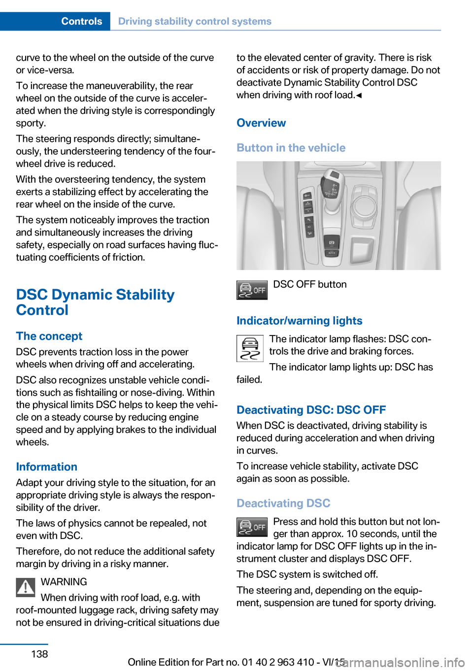
Overview
Button in the vehicle
DSC OFF button
Indicator/warning lights The indicator lamp flashes: DSC con‐
trols the drive and braking forces.
The indicator lamp lights up: DSC has
failed.
Deactivating DSC: DSC OFF
When DSC is deactivated, driving stability is
reduced during acceleration and when driving
in curves.
To increase vehicle stability, activate DSC
again as soon as possible.
Deactivating DSC Press and hold this button but not lon‐
ger than approx. 10 seconds, until the
indicator lamp for DSC OFF lights up in the in‐
strument cluster and displays DSC OFF.
The DSC system is switched off.
The steering and, depending on the equip‐
ment, suspension are tuned for sporty driving.
Seite 138ControlsDriving stability control systems138
Online Edition for Part no. 01 40 2 963 410 - VI/15
Page 156 of 275
System limits
Limits of ultrasonic measurement
Ultrasonic measuring might not function under
the following circumstances:▷For small children and animals.▷For persons with certain clothing, e.g.
coats.▷With external interference of the ultra‐
sound, e.g. from passing vehicles or loud
machines.▷When sensors are dirty, iced over, dam‐
aged or out of position.▷Under certain weather conditions such as
high relative humidity, rain, snowfall, ex‐
treme heat or strong wind.▷With tow bars and trailer couplings of other
vehicles.▷With thin or wedge-shaped objects.▷With moving objects.▷With elevated, protruding objects such as
ledges or cargo.▷With objects with corners and sharp edges.▷With objects with a fine surface structure
such as fences.▷For objects with porous surfaces.
Low objects already displayed, e.g., curbs, can
move into the blind area of the sensors before
or after a continuous tone sounds.
False warnings
PDC may issue a warning under the following conditions even though there is no obstacle
within the detection range:
▷In heavy rain.▷When sensors are very dirty or covered
with ice.▷When sensors are covered in snow.▷On rough road surfaces.▷On uneven surfaces, such as speed
bumps.▷In large buildings with right angles and
smooth walls, e.g., in underground ga‐
rages.▷In automatic car washes.▷Through heavy pollution.▷Due to other ultrasound sources, e.g.,
sweeping machines, high pressure steam
cleaners or neon lights.
Malfunction
A Check Control message is displayed.
The range of the sensors is shown as a shaded
area on the Control Display.
PDC has failed. Have the system checked.
Surround View
The concept Surround View comprises various camera as‐
sistance systems that help the driver when
parking, maneuvering, and at complex exits
and intersections.
▷Rearview camera, refer to page 156.▷Top View, refer to page 159.▷Side View, refer to page 161.
Rearview camera
The concept The rearview camera provides assistance in
parking and maneuvering backwards. The area
behind the vehicle is shown on the Control
Display.
Information WARNING
The system does not relieve from the
personal responsibility to correctly assess the
traffic situation. There is risk of an accident.
Adjust the driving style to the traffic condi‐
Seite 156ControlsDriving comfort156
Online Edition for Part no. 01 40 2 963 410 - VI/15
Page 159 of 275
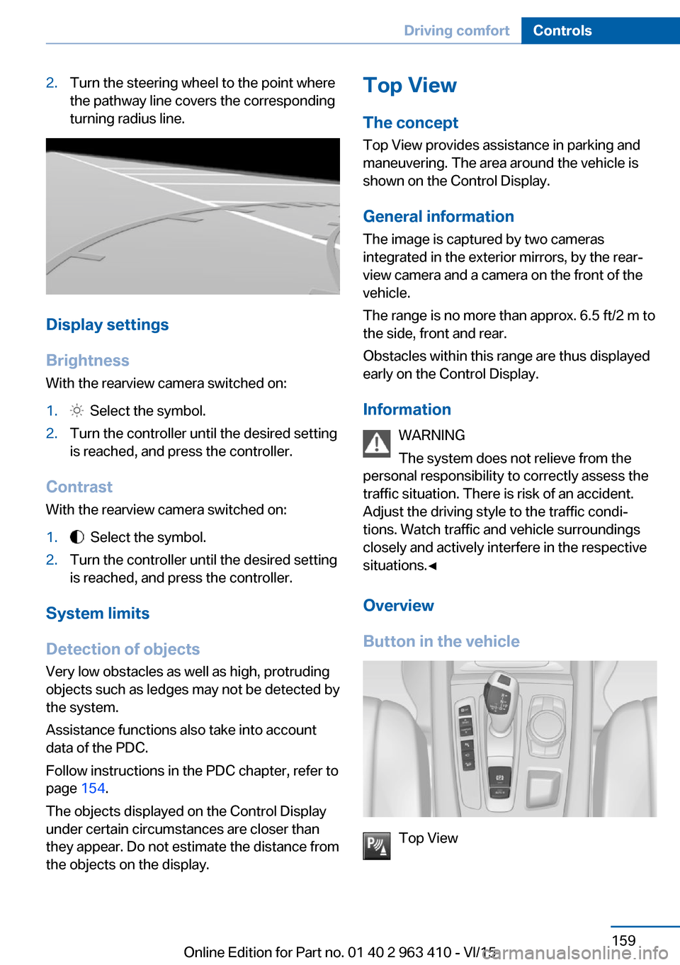
2.Turn the steering wheel to the point where
the pathway line covers the corresponding
turning radius line.
Display settings
Brightness
With the rearview camera switched on:
1. Select the symbol.2.Turn the controller until the desired setting
is reached, and press the controller.
Contrast
With the rearview camera switched on:
1. Select the symbol.2.Turn the controller until the desired setting
is reached, and press the controller.
System limits
Detection of objects
Very low obstacles as well as high, protruding
objects such as ledges may not be detected by
the system.
Assistance functions also take into account
data of the PDC.
Follow instructions in the PDC chapter, refer to
page 154.
The objects displayed on the Control Display
under certain circumstances are closer than
they appear. Do not estimate the distance from
the objects on the display.
Top View
The concept Top View provides assistance in parking and
maneuvering. The area around the vehicle is
shown on the Control Display.
General information The image is captured by two cameras
integrated in the exterior mirrors, by the rear‐
view camera and a camera on the front of the
vehicle.
The range is no more than approx. 6.5 ft/2 m to
the side, front and rear.
Obstacles within this range are thus displayed
early on the Control Display.
Information WARNING
The system does not relieve from the
personal responsibility to correctly assess the
traffic situation. There is risk of an accident.
Adjust the driving style to the traffic condi‐ tions. Watch traffic and vehicle surroundings
closely and actively interfere in the respective
situations.◀
Overview
Button in the vehicle
Top View
Seite 159Driving comfortControls159
Online Edition for Part no. 01 40 2 963 410 - VI/15
Page 161 of 275
2.Turn the controller until the desired setting
is reached, and press the controller.
Displaying the turning radius and
pathway lines
▷The static, red turning radius line shows
the space needed to the side of the vehicle
when the steering wheel is turned all the
way.▷The variable, green pathway line assists
you in assessing the amount of space ac‐
tually needed to the side of the vehicle.
The lane line depends on the engaged
gear and the current steering angle. The
track line is continuously adjusted for the
steering wheel movement.
"Parking aid lines"
Turning circle and pathway lines are displayed.
System limits
A Check Control message is displayed when a
camera is not working.
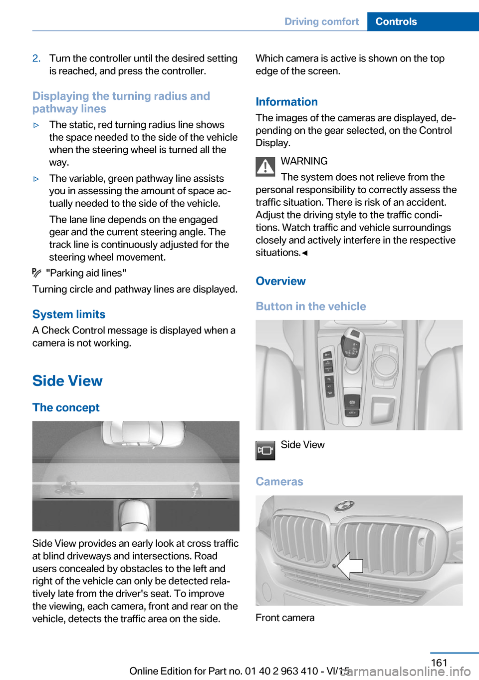
Side View The concept
Side View provides an early look at cross traffic
at blind driveways and intersections. Road
users concealed by obstacles to the left and
right of the vehicle can only be detected rela‐
tively late from the driver's seat. To improve
the viewing, each camera, front and rear on the
vehicle, detects the traffic area on the side.
Which camera is active is shown on the top
edge of the screen.
Information The images of the cameras are displayed, de‐
pending on the gear selected, on the Control
Display.
WARNING
The system does not relieve from the
personal responsibility to correctly assess the
traffic situation. There is risk of an accident.
Adjust the driving style to the traffic condi‐
tions. Watch traffic and vehicle surroundings
closely and actively interfere in the respective
situations.◀
Overview
Button in the vehicle
Side View
Cameras
Front camera
Seite 161Driving comfortControls161
Online Edition for Part no. 01 40 2 963 410 - VI/15