Control display BMW X5 2015 F15 Service Manual
[x] Cancel search | Manufacturer: BMW, Model Year: 2015, Model line: X5, Model: BMW X5 2015 F15Pages: 275, PDF Size: 6.46 MB
Page 98 of 275
Using the thumbwheel, select the desired set‐
ting and confirm it by pushing the thumbwheel.
On-board computer
Indication in the info display The information from the on-
board computer is shown in the
info display in the instrument
cluster.
Calling up information on the info
display
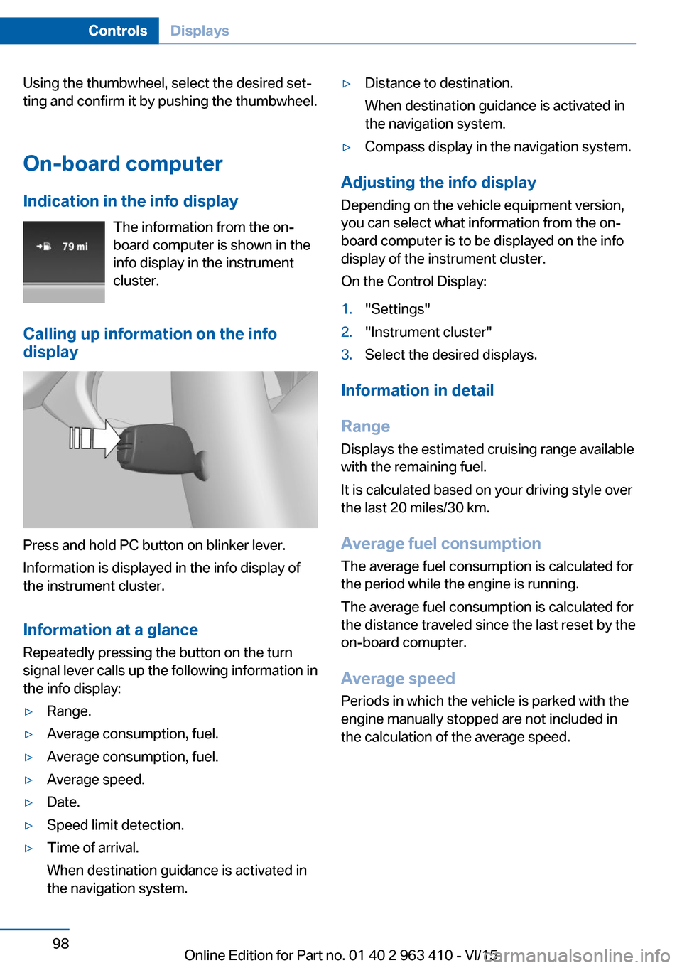
Press and hold PC button on blinker lever.
Information is displayed in the info display of
the instrument cluster.
Information at a glance
Repeatedly pressing the button on the turn
signal lever calls up the following information in
the info display:
▷Range.▷Average consumption, fuel.▷Average consumption, fuel.▷Average speed.▷Date.▷Speed limit detection.▷Time of arrival.
When destination guidance is activated in
the navigation system.▷Distance to destination.
When destination guidance is activated in
the navigation system.▷Compass display in the navigation system.
Adjusting the info display
Depending on the vehicle equipment version,
you can select what information from the on-
board computer is to be displayed on the info
display of the instrument cluster.
On the Control Display:
1."Settings"2."Instrument cluster"3.Select the desired displays.
Information in detail
Range
Displays the estimated cruising range available
with the remaining fuel.
It is calculated based on your driving style over
the last 20 miles/30 km.
Average fuel consumption
The average fuel consumption is calculated for
the period while the engine is running.
The average fuel consumption is calculated for
the distance traveled since the last reset by the
on-board comupter.
Average speed
Periods in which the vehicle is parked with the
engine manually stopped are not included in
the calculation of the average speed.
Seite 98ControlsDisplays98
Online Edition for Part no. 01 40 2 963 410 - VI/15
Page 99 of 275
Resetting average values
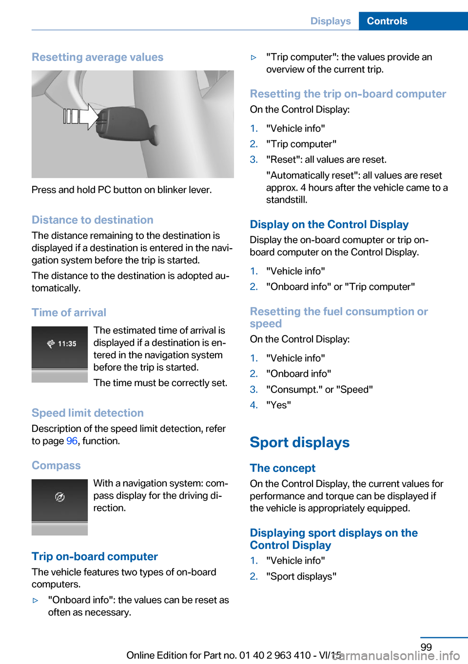
Press and hold PC button on blinker lever.Distance to destination
The distance remaining to the destination is
displayed if a destination is entered in the navi‐
gation system before the trip is started.
The distance to the destination is adopted au‐
tomatically.
Time of arrival The estimated time of arrival is
displayed if a destination is en‐
tered in the navigation system
before the trip is started.
The time must be correctly set.
Speed limit detection
Description of the speed limit detection, refer
to page 96, function.
Compass With a navigation system: com‐
pass display for the driving di‐
rection.
Trip on-board computer The vehicle features two types of on-board
computers.
▷"Onboard info": the values can be reset as
often as necessary.▷"Trip computer": the values provide an
overview of the current trip.
Resetting the trip on-board computer
On the Control Display:
1."Vehicle info"2."Trip computer"3."Reset": all values are reset.
"Automatically reset": all values are reset
approx. 4 hours after the vehicle came to a
standstill.
Display on the Control Display
Display the on-board comupter or trip on-
board computer on the Control Display.
1."Vehicle info"2."Onboard info" or "Trip computer"
Resetting the fuel consumption or
speed
On the Control Display:
1."Vehicle info"2."Onboard info"3."Consumpt." or "Speed"4."Yes"
Sport displays
The concept
On the Control Display, the current values for
performance and torque can be displayed if
the vehicle is appropriately equipped.
Displaying sport displays on the
Control Display
1."Vehicle info"2."Sport displays"Seite 99DisplaysControls99
Online Edition for Part no. 01 40 2 963 410 - VI/15
Page 100 of 275
Speed warning
The concept Displays a speed, when reached, should cause
a warning to be issued.
The warning is repeated if the vehicle speed
drops below the set speed once by at least
3 mph/5 km/h.
Displaying, setting or changing the
speed warning
On the Control Display:1."Settings"2."Speed"3."Warning at:"4.Turn the controller until the desired speed
is displayed.5.Press the controller.
Speed warning is stored.
Activating/deactivating the speed
warning
On the Control Display:
1."Settings"2."Speed"3."Warning"4.Press the controller.
Setting your current speed as the
speed warning
On the Control Display:
1."Settings"2."Speed"3."Select current speed"4.Press the controller.
The current vehicle speed is stored as the
speed warning.Settings on the Control
Display
Time
Setting the time zone1."Settings"2."Time/Date"3."Time zone:"4.Select the desired time zone.
The time zone is stored.
Setting the time
1."Settings"2."Time/Date"3."Time:"4.Turn the controller until the desired hours
are displayed.5.Press the controller.6.Turn the controller until the desired mi‐
nutes are displayed.7.Press the controller.
The time is stored.
Setting the time format
1."Settings"2."Time/Date"3."Format:"4.Select the desired format.
The time format is stored.
Automatic time setting Depending on your vehicle's optional features,
the time, date and, if needed, the time zone are
updated automatically.
1."Settings"2."Time/Date"3."Auto time set"Seite 100ControlsDisplays100
Online Edition for Part no. 01 40 2 963 410 - VI/15
Page 101 of 275
Date
Setting the date1."Settings"2."Time/Date"3."Date:"4.Turn the controller until the desired day is
displayed.5.Press the controller.6.Make the necessary settings for the month
and year.
The date is stored.
Setting the date format
1."Settings"2."Time/Date"3."Format:"4.Select the desired format.
The date format is stored.
Language
Setting the language
To set the language on the Control Display:
1."Settings"2."Language/Units"3."Language:"4.Select the desired language.
Settings are stored for the profile currently
used.
Setting the voice dialog
Voice dialog for the voice activation system,
refer to page 27.
Units of measurement
Setting the units of measurement
To set the units for fuel consumption, route/
distance and temperature:1."Settings"2."Language/Units"3.Select the desired menu item.4.Select the desired unit.
Settings are stored for the profile currently
used.
Brightness
Setting the brightness To set the brightness of the Control Display:
1."Settings"2."Control display"3."Brightness"4.Turn the controller until the desired bright‐
ness is set.5.Press the controller.
Settings are stored for the profile currently
used.
Depending on the light conditions, the bright‐
ness settings may not be clearly visible.
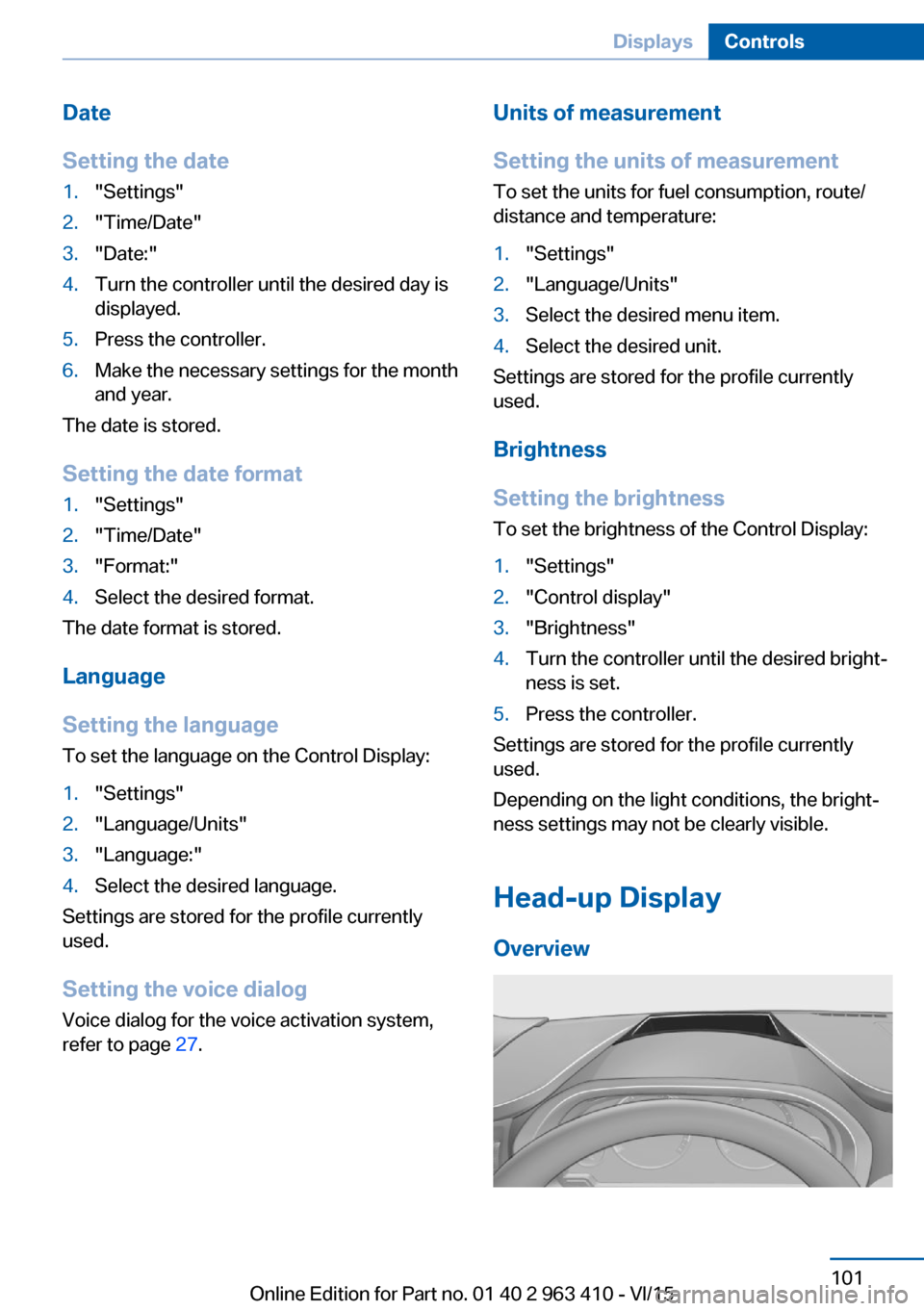
Head-up Display
Overview
Seite 101DisplaysControls101
Online Edition for Part no. 01 40 2 963 410 - VI/15
Page 102 of 275
The conceptThis system projects important information
into the driver's field of vision, e. g., the speed.
The driver can get information without averting
his or her eyes from the road.
Information
Follow the instructions for cleaning the Head-
up Display, refer to page 257.
Display visibility The visibility of the displays in the Head-up
Display is influenced by the following factors:▷Certain sitting positions.▷Objects on the cover of the Head-up Dis‐
play.▷Sunglasses with certain polarization filters.▷Wet roads.▷Unfavorable light conditions.
If the image is distorted, have the basic set‐
tings checked by a dealer’s service center or
another qualified service center or repair shop.
Switching on/off
1."Settings"2."Head-Up Display"3."Head-Up Display"
Display
Overview
The following information is displayed on the
Head-up Display:
▷Speed.▷Navigation system.▷Check Control messages.▷Selection list from the instrument cluster.▷Driver assistance systems.
Some of this information is only displayed
briefly as needed.
Selecting displays in the Head-up Display
On the Control Display:1."Settings"2."Head-Up Display"3."Displayed information"4.Select the desired displays in the Head-up
Display.
Settings are stored for the profile currently
used.
Setting the brightness The brightness is automatically adjusted to the
ambient brightness.
The basic setting can be adjusted manually.
On the Control Display:
1."Settings"2."Head-Up Display"3."Brightness"4.Turn the controller until the desired bright‐
ness is set.5.Press the controller.
When the low beams are activated, the bright‐
ness of the Head-up Display can be addition‐
ally influenced using the instrument lighting.
Settings are stored for the profile currently
used.
Adjusting the height
On the Control Display:
1."Settings"2."Head-Up Display"3."Height"4.Turn the controller until the desired height
is reached.5.Press the controller.
Settings are stored for the profile currently
used.
Seite 102ControlsDisplays102
Online Edition for Part no. 01 40 2 963 410 - VI/15
Page 103 of 275
Setting the rotation
The screen of the Head-up Display can be ro‐
tated around its own axis.
On the Control Display:1."Settings"2."Head-Up Display"3."Rotation"4.Turn the controller until the desired setting
is selected.5.Press the controller.
Settings are stored for the profile currently
used.
Special windshield
The windshield is part of the system.
The shape of the windshield makes it possible
to display a precise image.
A film in the windshield prevents double im‐
ages from being displayed.
For this reason, it is strongly suggested to
have the special windshield replaced by a
dealer’s service center or another qualified
service center or repair shop.
Seite 103DisplaysControls103
Online Edition for Part no. 01 40 2 963 410 - VI/15
Page 105 of 275
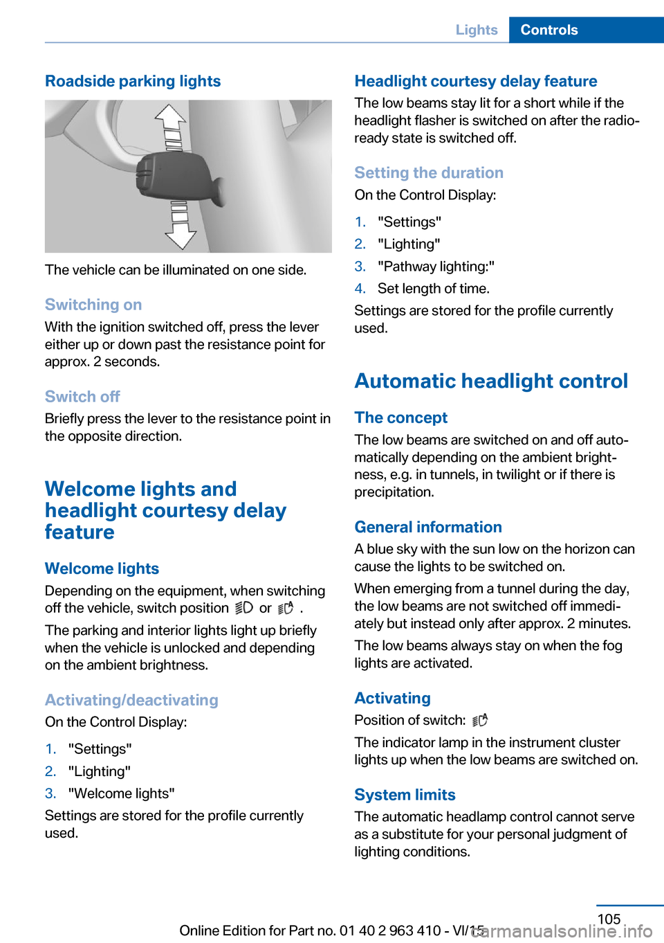
Roadside parking lights
The vehicle can be illuminated on one side.
Switching on With the ignition switched off, press the lever
either up or down past the resistance point for
approx. 2 seconds.
Switch off Briefly press the lever to the resistance point in
the opposite direction.
Welcome lights and
headlight courtesy delay
feature
Welcome lights Depending on the equipment, when switching
off the vehicle, switch position
or .
The parking and interior lights light up briefly
when the vehicle is unlocked and depending
on the ambient brightness.
Activating/deactivating
On the Control Display:
1."Settings"2."Lighting"3."Welcome lights"
Settings are stored for the profile currently
used.
Headlight courtesy delay feature
The low beams stay lit for a short while if the
headlight flasher is switched on after the radio-
ready state is switched off.
Setting the duration
On the Control Display:1."Settings"2."Lighting"3."Pathway lighting:"4.Set length of time.
Settings are stored for the profile currently
used.
Automatic headlight control
The concept The low beams are switched on and off auto‐
matically depending on the ambient bright‐
ness, e.g. in tunnels, in twilight or if there is
precipitation.
General information
A blue sky with the sun low on the horizon can
cause the lights to be switched on.
When emerging from a tunnel during the day,
the low beams are not switched off immedi‐
ately but instead only after approx. 2 minutes.
The low beams always stay on when the fog
lights are activated.
Activating Position of switch:
The indicator lamp in the instrument cluster
lights up when the low beams are switched on.
System limits
The automatic headlamp control cannot serve
as a substitute for your personal judgment of
lighting conditions.
Seite 105LightsControls105
Online Edition for Part no. 01 40 2 963 410 - VI/15
Page 106 of 275
E. g. the sensors are unable to detect fog or
hazy weather. To avoid safety risks under
these conditions, you should always switch on
the lights manually.
Daytime running lights Position of switch:
, ,
The daytime running lights light up when the
ignition is switched on. After the ignition is
switched off, the parking lights light up in posi‐
tion
.
Activating/deactivating In some countries, daytime running lights are
mandatory, so it may not be possible to deacti‐
vate the daytime running lights.
On the Control Display:
1."Settings"2."Lighting"3."Daytime running lamps"
Settings are stored for the profile currently
used.
Adaptive Light Control
The concept Adaptive Light Control is a variable headlight
control system that enables dynamic illumina‐
tion of the road surface.
Depending on the steering angle and other pa‐
rameters, the light from the headlight follows
the course of the road.
In tight curves, e.g., on mountainous roads or
when turning, an additional, corner-illuminating
lamp is switched on that lights up the inside of
the curve when the vehicle is moving below a
certain speed.
Activating
Position of switch
with the ignition
switched on.
To avoid blinding oncoming traffic, the Adap‐
tive Light Control does not swivel to the driv‐
er's side when the vehicle is at a standstill.
The turning lights are automatically switched
on depending on the steering angle or the use
of turn signals.
When driving in reverse, the turning lights may
be automatically switched on regardless of the
steering angle.
Self-leveling headlights The self-leveling headlights compensate for
acceleration and braking operations in order
not to blind the oncoming traffic and to achieve
optimum illumination of the roadway.
Malfunction A Check Control message is displayed.
Adaptive Light Control is malfunctioning or has
failed. Have the system checked as soon as
possible.
High-beam Assistant
The concept When the low beams are activated, this system
automatically switches the high beams on and
off or suppresses the light in the areas that
blind oncoming traffic. The procedure is con‐
trolled by a camera on the front of the interior
rearview mirror. The assistant ensures that the
high beams are activated whenever the traffic
situation allows. The driver can intervene at
any time and switch the high beams on and off
as usual. In the low speed range, the high
beams are not switched on by the system.
Seite 106ControlsLights106
Online Edition for Part no. 01 40 2 963 410 - VI/15
Page 108 of 275
When the high beams or headlight flasher are
activated, the front fog lights are not switched
on.
Instrument lighting Adjusting The parking lights or low beams
must be switched on to adjust
the brightness.
Adjust the brightness with the
thumbwheel.
Interior lights
General information The interior lights, footwell lights, access lights
and courtesy lights are controlled automati‐
cally.
Thumb wheel for the instrument lighting con‐
trols brightness of some of these features.
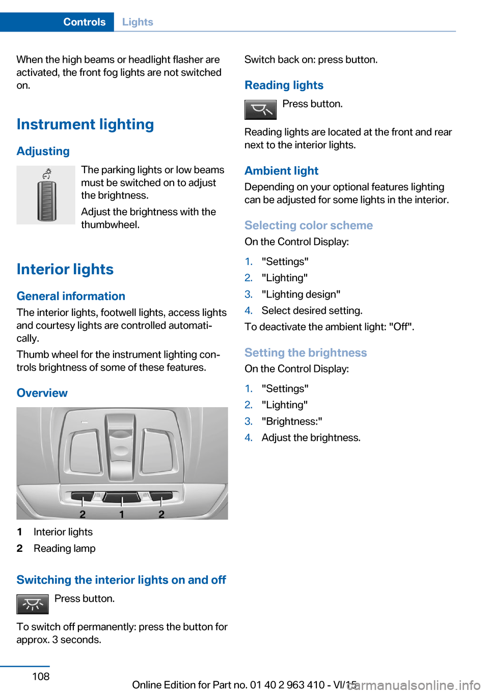
Overview1Interior lights2Reading lamp
Switching the interior lights on and off Press button.
To switch off permanently: press the button for
approx. 3 seconds.
Switch back on: press button.
Reading lights Press button.
Reading lights are located at the front and rear
next to the interior lights.
Ambient light Depending on your optional features lighting
can be adjusted for some lights in the interior.
Selecting color scheme
On the Control Display:1."Settings"2."Lighting"3."Lighting design"4.Select desired setting.
To deactivate the ambient light: "Off".
Setting the brightness On the Control Display:
1."Settings"2."Lighting"3."Brightness:"4.Adjust the brightness.Seite 108ControlsLights108
Online Edition for Part no. 01 40 2 963 410 - VI/15
Page 112 of 275
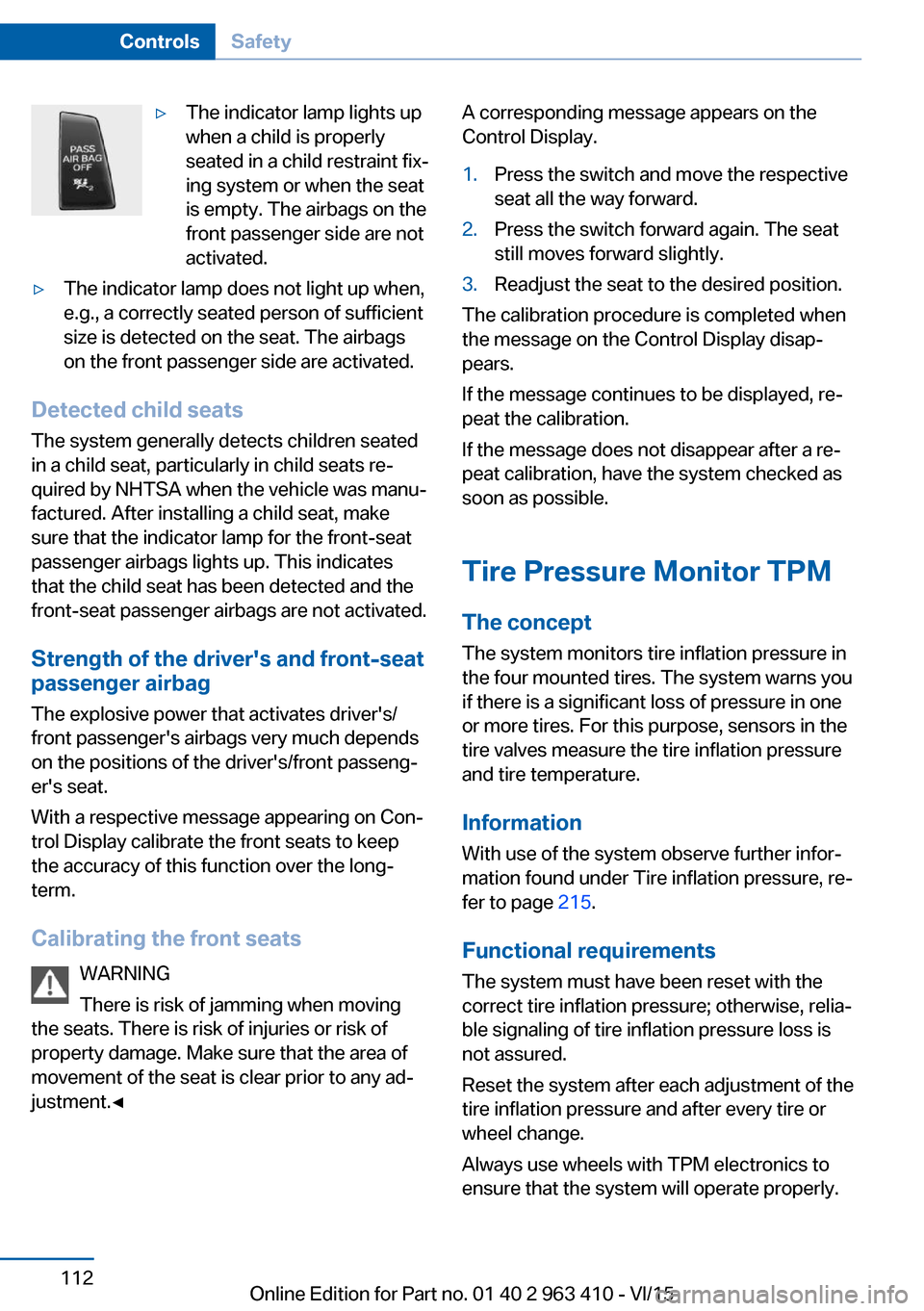
▷The indicator lamp lights up
when a child is properly
seated in a child restraint fix‐
ing system or when the seat
is empty. The airbags on the
front passenger side are not
activated.▷The indicator lamp does not light up when,
e.g., a correctly seated person of sufficient
size is detected on the seat. The airbags
on the front passenger side are activated.
Detected child seats
The system generally detects children seated
in a child seat, particularly in child seats re‐
quired by NHTSA when the vehicle was manu‐ factured. After installing a child seat, make
sure that the indicator lamp for the front-seat
passenger airbags lights up. This indicates
that the child seat has been detected and the
front-seat passenger airbags are not activated.
Strength of the driver's and front-seat
passenger airbag
The explosive power that activates driver's/
front passenger's airbags very much depends
on the positions of the driver's/front passeng‐ er's seat.
With a respective message appearing on Con‐
trol Display calibrate the front seats to keep the accuracy of this function over the long-
term.
Calibrating the front seats WARNING
There is risk of jamming when moving
the seats. There is risk of injuries or risk of
property damage. Make sure that the area of
movement of the seat is clear prior to any ad‐
justment.◀
A corresponding message appears on the
Control Display.1.Press the switch and move the respective
seat all the way forward.2.Press the switch forward again. The seat
still moves forward slightly.3.Readjust the seat to the desired position.
The calibration procedure is completed when
the message on the Control Display disap‐
pears.
If the message continues to be displayed, re‐
peat the calibration.
If the message does not disappear after a re‐
peat calibration, have the system checked as
soon as possible.
Tire Pressure Monitor TPM
The concept The system monitors tire inflation pressure in
the four mounted tires. The system warns you
if there is a significant loss of pressure in one
or more tires. For this purpose, sensors in the
tire valves measure the tire inflation pressure
and tire temperature.
Information With use of the system observe further infor‐
mation found under Tire inflation pressure, re‐
fer to page 215.
Functional requirements
The system must have been reset with the
correct tire inflation pressure; otherwise, relia‐
ble signaling of tire inflation pressure loss is
not assured.
Reset the system after each adjustment of the
tire inflation pressure and after every tire or
wheel change.
Always use wheels with TPM electronics to
ensure that the system will operate properly.
Seite 112ControlsSafety112
Online Edition for Part no. 01 40 2 963 410 - VI/15