ESP BMW X6 2013 E71 User Guide
[x] Cancel search | Manufacturer: BMW, Model Year: 2013, Model line: X6, Model: BMW X6 2013 E71Pages: 345, PDF Size: 9.45 MB
Page 49 of 345
AdjustingVehicle equipment
This chapter describes all series equipment as
well as country-specific and special equipment
offered for this model series.Therefore, it also
describes equipment that may not be found in
your vehicle, for instance due to the selected
special equipment or the country version. This
also applies to safety-related functions and
systems.
Sitting safely
The ideal seating position can make a vital
contribution to relaxed, fatigue-free driving.
The seating position plays an important role in
an accident in combination with:▷Safety belts, refer to page 54.▷Head restraints, refer to page 55.▷Airbags, refer to page 95.
Seats
Note before adjusting Do not adjust the seat while driving
Never attempt to adjust the driver's seat
while driving. The seat could respond with un‐
expected movement and the ensuing loss of
vehicle control could lead to an accident.◀
Do not incline the backrest too far to the
rear
Do not incline the backrest on the front pas‐
senger side too far to the rear during driving.
Otherwise, there is the danger of sliding under
the safety belt in an accident. This would elimi‐
nate the protection normally provided by the
belt.◀
Adjusting manually
Forward/backward
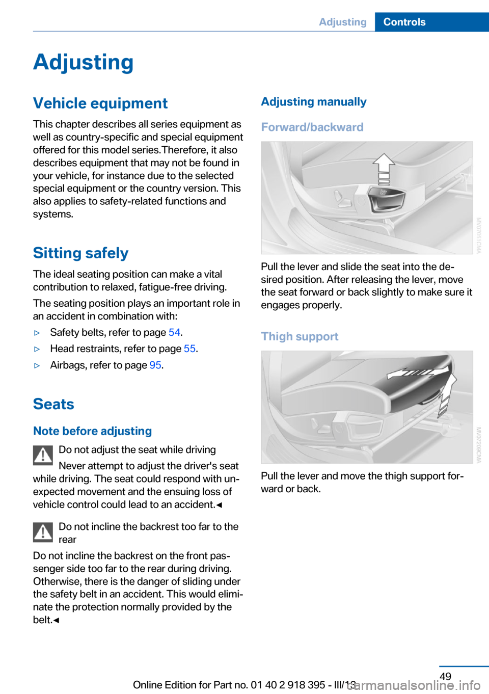
Pull the lever and slide the seat into the de‐
sired position. After releasing the lever, move
the seat forward or back slightly to make sure it
engages properly.
Thigh support
Pull the lever and move the thigh support for‐
ward or back.
Seite 49AdjustingControls49
Online Edition for Part no. 01 40 2 918 395 - III/13
Page 53 of 345
Active seat ventilation and
seat heating
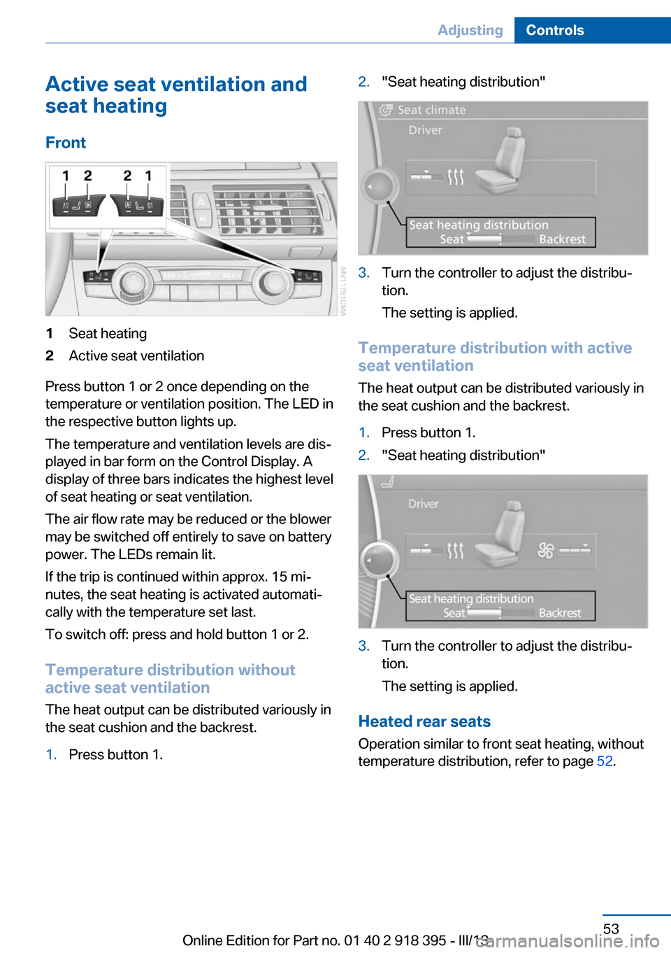
Front1Seat heating2Active seat ventilation
Press button 1 or 2 once depending on the
temperature or ventilation position. The LED in
the respective button lights up.
The temperature and ventilation levels are dis‐
played in bar form on the Control Display. A
display of three bars indicates the highest level
of seat heating or seat ventilation.
The air flow rate may be reduced or the blower
may be switched off entirely to save on battery
power. The LEDs remain lit.
If the trip is continued within approx. 15 mi‐
nutes, the seat heating is activated automati‐
cally with the temperature set last.
To switch off: press and hold button 1 or 2.
Temperature distribution without
active seat ventilation
The heat output can be distributed variously in
the seat cushion and the backrest.
1.Press button 1.2."Seat heating distribution"3.Turn the controller to adjust the distribu‐
tion.
The setting is applied.
Temperature distribution with active
seat ventilation
The heat output can be distributed variously in
the seat cushion and the backrest.
1.Press button 1.2."Seat heating distribution"3.Turn the controller to adjust the distribu‐
tion.
The setting is applied.
Heated rear seats Operation similar to front seat heating, without
temperature distribution, refer to page 52.
Seite 53AdjustingControls53
Online Edition for Part no. 01 40 2 918 395 - III/13
Page 55 of 345
Unbuckling the belt1.Hold the belt firmly.2.Press the red button in the belt buckle.3.Guide the belt back into its reel.
The shoulder strap's anchorage point will be
correct for adult seat occupants of every build
if the seat is correctly adjusted, refer to
page 49.
The two rear safety belt buckles integrated
into the rear seat are for passengers sitting on
the left and right. The belt buckle embossed
with the word CENTER is intended exclusively
for use by passengers riding in the center posi‐
tion.
Safety belt reminder for the driver's
and front passenger seat
The indicator lamp lights up and a
signal sounds. In addition, a message
appears on the Control Display.
Check whether the safety belt has been fas‐
tened correctly.
The safety belt reminder is active at speeds
above approx. 5 mph/8 km/h. It can also be ac‐
tivated if objects are placed on the front pas‐
senger seat.
Damage to safety belts In the case of strain caused by accidents or
damage:
Have the safety belts, including the safety belt
tensioners, replaced and have the belt anchors
checked.
Checking and replacing safety belts
Have the work performed only by your
service center; otherwise, it cannot be ensured
that this safety feature will function properly.◀
Belt-force limiter
The effect of the belt-force limiter on the driv‐
er's seat is dependent on the position of the
driver's seat.
To maintain the long-term accuracy of this
function, the driver's seat must be calibrated if
a corresponding message is displayed on the
Control Display.
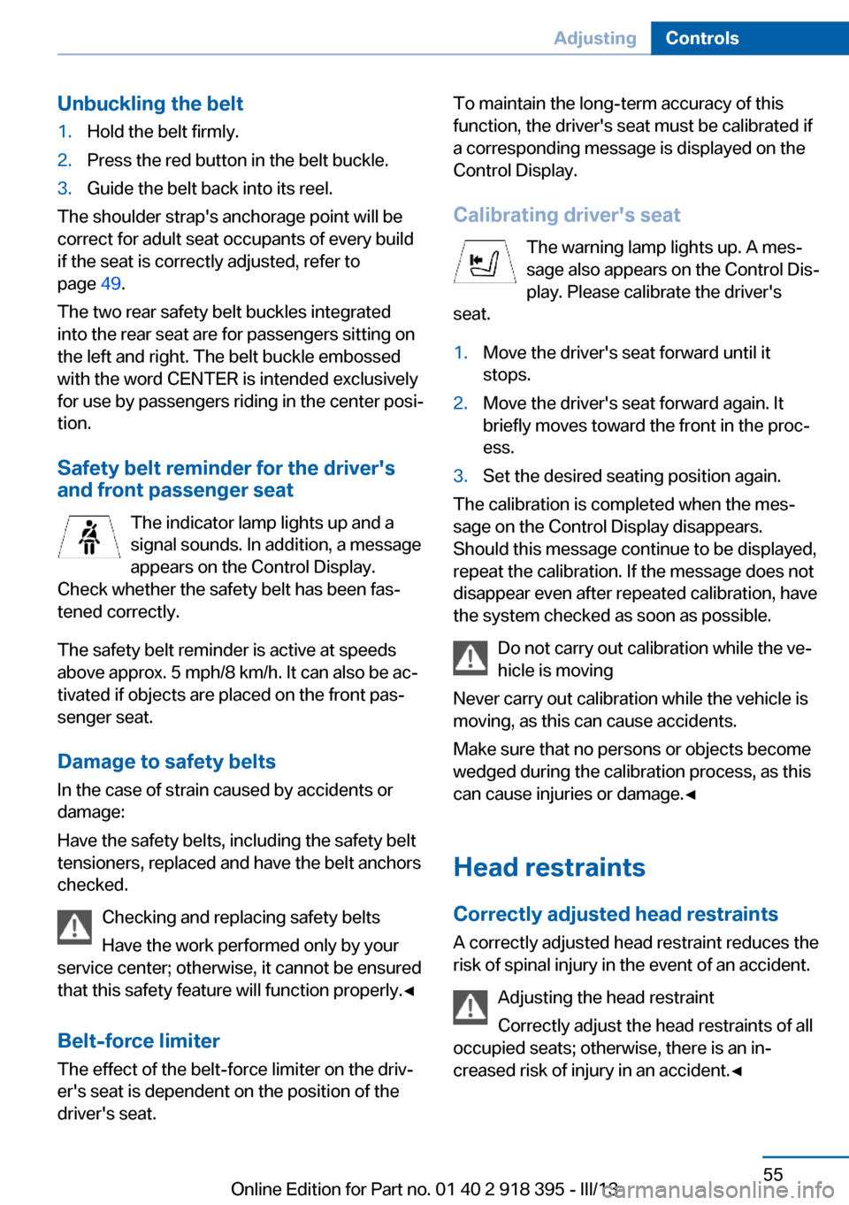
Calibrating driver's seat The warning lamp lights up. A mes‐
sage also appears on the Control Dis‐
play. Please calibrate the driver's
seat.1.Move the driver's seat forward until it
stops.2.Move the driver's seat forward again. It
briefly moves toward the front in the proc‐
ess.3.Set the desired seating position again.
The calibration is completed when the mes‐
sage on the Control Display disappears.
Should this message continue to be displayed,
repeat the calibration. If the message does not
disappear even after repeated calibration, have
the system checked as soon as possible.
Do not carry out calibration while the ve‐
hicle is moving
Never carry out calibration while the vehicle is
moving, as this can cause accidents.
Make sure that no persons or objects become
wedged during the calibration process, as this
can cause injuries or damage.◀
Head restraints Correctly adjusted head restraints
A correctly adjusted head restraint reduces the
risk of spinal injury in the event of an accident.
Adjusting the head restraint
Correctly adjust the head restraints of all
occupied seats; otherwise, there is an in‐
creased risk of injury in an accident.◀
Seite 55AdjustingControls55
Online Edition for Part no. 01 40 2 918 395 - III/13
Page 58 of 345
Comfort function1.Open the driver's door after unlocking or
switch on the radio ready state, refer to
page 67.2.Briefly press the desired memory but‐
ton 1 or 2.
The seat is automatically moved to the stored
position.
The procedure stops when a switch for setting
the seat or one of the memory buttons is
pressed.
Safety mode
1.Close the driver's door and switch the igni‐
tion on or off, refer to page 67.2.Press and hold the desired memory button
1 or 2 until the setting procedure is com‐
pleted.
Mirrors
Exterior mirrors
General information The mirror on the passenger side is more
curved than the driver's mirror.
Estimating distances correctly
Objects reflected in the mirror are closer
than they appear. Do not estimate the distance
to the traffic behind you based on what you
see in the mirror, as this will increase your risk
of an accident.◀
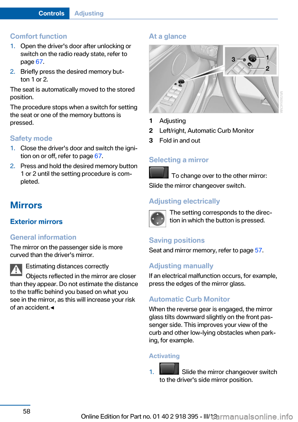
At a glance1Adjusting2Left/right, Automatic Curb Monitor3Fold in and out
Selecting a mirror
To change over to the other mirror:
Slide the mirror changeover switch.
Adjusting electrically The setting corresponds to the direc‐
tion in which the button is pressed.
Saving positions
Seat and mirror memory, refer to page 57.
Adjusting manually If an electrical malfunction occurs, for example,
press the edges of the mirror glass.
Automatic Curb Monitor When the reverse gear is engaged, the mirror
glass tilts downward slightly on the front pas‐
senger side. This improves your view of the
curb and other low-lying obstacles when park‐
ing, for example.
Activating
1. Slide the mirror changeover switch
to the driver's side mirror position.
Seite 58ControlsAdjusting58
Online Edition for Part no. 01 40 2 918 395 - III/13
Page 72 of 345
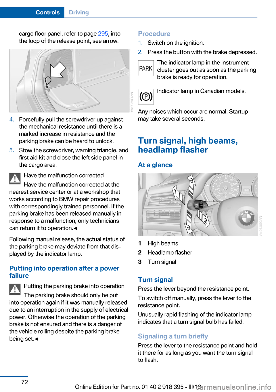
cargo floor panel, refer to page 295, into
the loop of the release point, see arrow.4.Forcefully pull the screwdriver up against
the mechanical resistance until there is a
marked increase in resistance and the
parking brake can be heard to unlock.5.Stow the screwdriver, warning triangle, and
first aid kit and close the left side panel in
the cargo area.
Have the malfunction corrected
Have the malfunction corrected at the
nearest service center or at a workshop that
works according to BMW repair procedures
with correspondingly trained personnel. If the
parking brake has been released manually in
response to a malfunction, only technicians
can return it to operation.◀
Following manual release, the actual status of
the parking brake may deviate from that dis‐
played by the indicator lamp.
Putting into operation after a power failure
Putting the parking brake into operation
The parking brake should only be put
into operation again if it was manually released
due to an interruption in the supply of electrical
power. Otherwise the operation of the parking
brake is not ensured and there is a danger of
the vehicle rolling despite the parking brake
being set.◀
Procedure1.Switch on the ignition.2.Press the button with the brake depressed.
The indicator lamp in the instrument
cluster goes out as soon as the parking
brake is ready for operation.
Indicator lamp in Canadian models.
Any noises which occur are normal. Startup
may take several seconds.
Turn signal, high beams,
headlamp flasher
At a glance
1High beams2Headlamp flasher3Turn signal
Turn signal
Press the lever beyond the resistance point.
To switch off manually, press the lever to the
resistance point.
Unusually rapid flashing of the indicator lamp
indicates that a turn signal bulb has failed.
Signaling a turn briefly
Press the lever to the resistance point and hold
it there for as long as you want the turn signal
to flash.
Seite 72ControlsDriving72
Online Edition for Part no. 01 40 2 918 395 - III/13
Page 79 of 345
DisplaysVehicle equipmentThis chapter describes all series equipment as
well as country-specific and special equipment
offered for this model series.Therefore, it also
describes equipment that may not be found in
your vehicle, for instance due to the selected
special equipment or the country version. This
also applies to safety-related functions and
systems.
Odometer, external
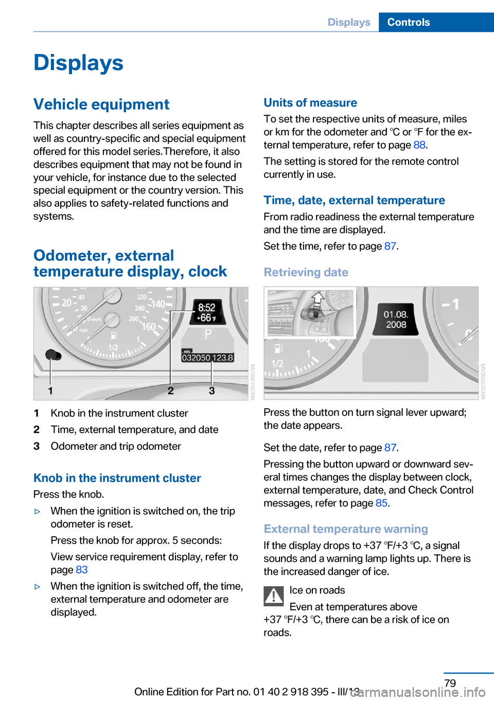
temperature display, clock1Knob in the instrument cluster2Time, external temperature, and date3Odometer and trip odometer
Knob in the instrument cluster
Press the knob.
▷When the ignition is switched on, the trip
odometer is reset.
Press the knob for approx. 5 seconds:
View service requirement display, refer to
page 83▷When the ignition is switched off, the time,
external temperature and odometer are
displayed.Units of measure
To set the respective units of measure, miles
or km for the odometer and ℃ or ℉ for the ex‐
ternal temperature, refer to page 88.
The setting is stored for the remote control
currently in use.
Time, date, external temperature From radio readiness the external temperature
and the time are displayed.
Set the time, refer to page 87.
Retrieving date
Press the button on turn signal lever upward;
the date appears.
Set the date, refer to page 87.
Pressing the button upward or downward sev‐
eral times changes the display between clock,
external temperature, date, and Check Control
messages, refer to page 85.
External temperature warning If the display drops to +37 ℉/+3 ℃, a signal
sounds and a warning lamp lights up. There is
the increased danger of ice.
Ice on roads
Even at temperatures above
+37 ℉/+3 ℃, there can be a risk of ice on
roads.
Seite 79DisplaysControls79
Online Edition for Part no. 01 40 2 918 395 - III/13
Page 81 of 345
▷Hot engine: the pointer is at the high tem‐
perature end. Switch off the engine imme‐
diately and allow it to cool down.
If the engine oil temperature is too high, a mes‐
sage appears on the Control Display.
Check the oil level, refer to page 290.
Fuel gauge
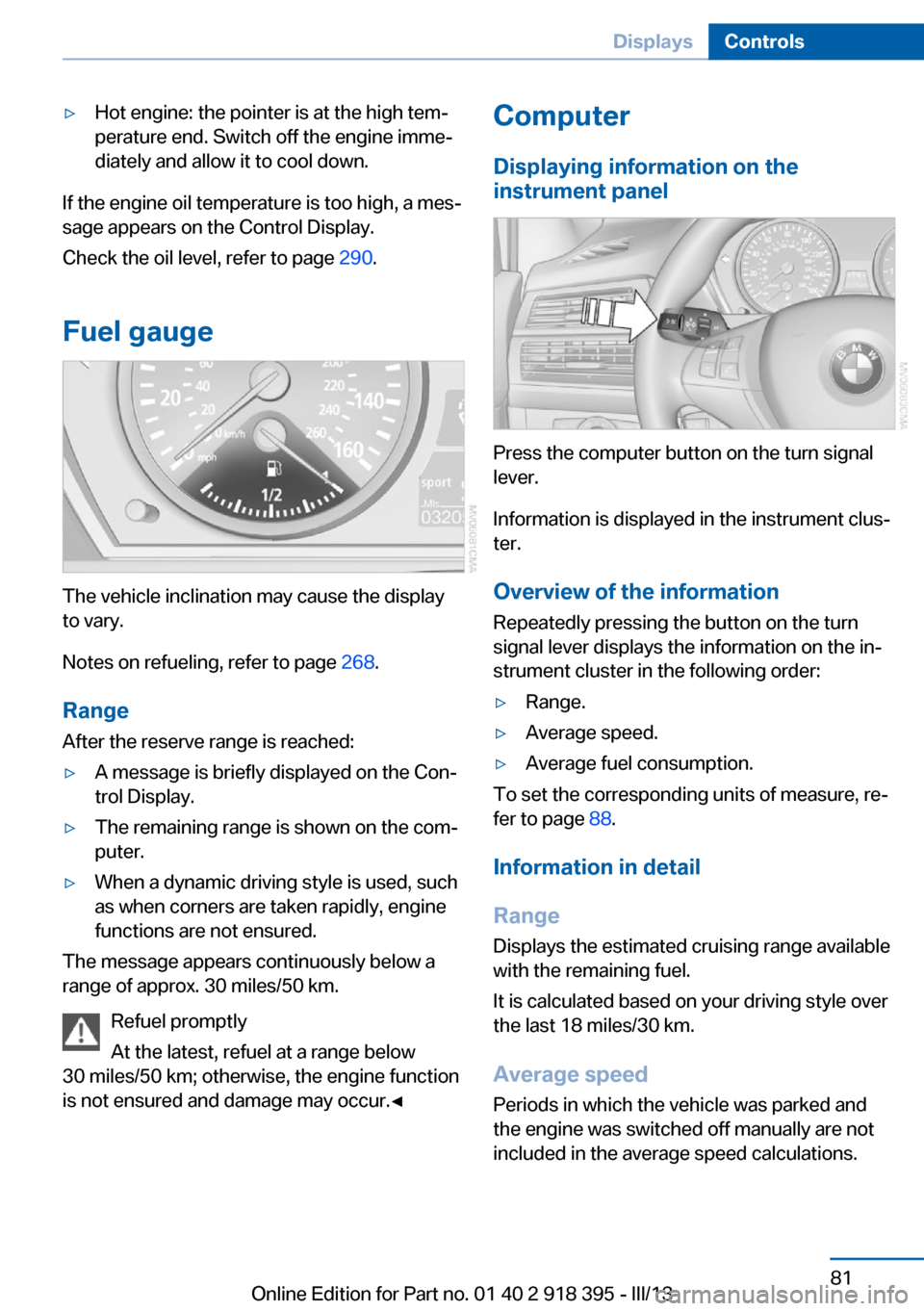
The vehicle inclination may cause the display
to vary.
Notes on refueling, refer to page 268.
Range
After the reserve range is reached:
▷A message is briefly displayed on the Con‐
trol Display.▷The remaining range is shown on the com‐
puter.▷When a dynamic driving style is used, such
as when corners are taken rapidly, engine
functions are not ensured.
The message appears continuously below a
range of approx. 30 miles/50 km.
Refuel promptly
At the latest, refuel at a range below
30 miles/50 km; otherwise, the engine function
is not ensured and damage may occur.◀
Computer
Displaying information on the
instrument panel
Press the computer button on the turn signal
lever.
Information is displayed in the instrument clus‐
ter.
Overview of the information Repeatedly pressing the button on the turn
signal lever displays the information on the in‐
strument cluster in the following order:
▷Range.▷Average speed.▷Average fuel consumption.
To set the corresponding units of measure, re‐
fer to page 88.
Information in detail
Range
Displays the estimated cruising range available
with the remaining fuel.
It is calculated based on your driving style over
the last 18 miles/30 km.
Average speed
Periods in which the vehicle was parked and
the engine was switched off manually are not
included in the average speed calculations.
Seite 81DisplaysControls81
Online Edition for Part no. 01 40 2 918 395 - III/13
Page 82 of 345
With the trip computer, refer to page 82, you
can have the average speed displayed for an
additional distance.
To reset the average speed: press the button
on the turn indicator lever for approx. 2 sec‐
onds.
Average fuel consumption
This is calculated for the period during which
the engine is running.
The average consumption is computed based
on the distance traveled since the last time the
computer was reset.
You can have the average consumption for an‐
other trip displayed, refer to Displays on the
Control Display below.
To reset the average consumption: press the
button on the turn indicator lever for ap‐
prox. 2 seconds.
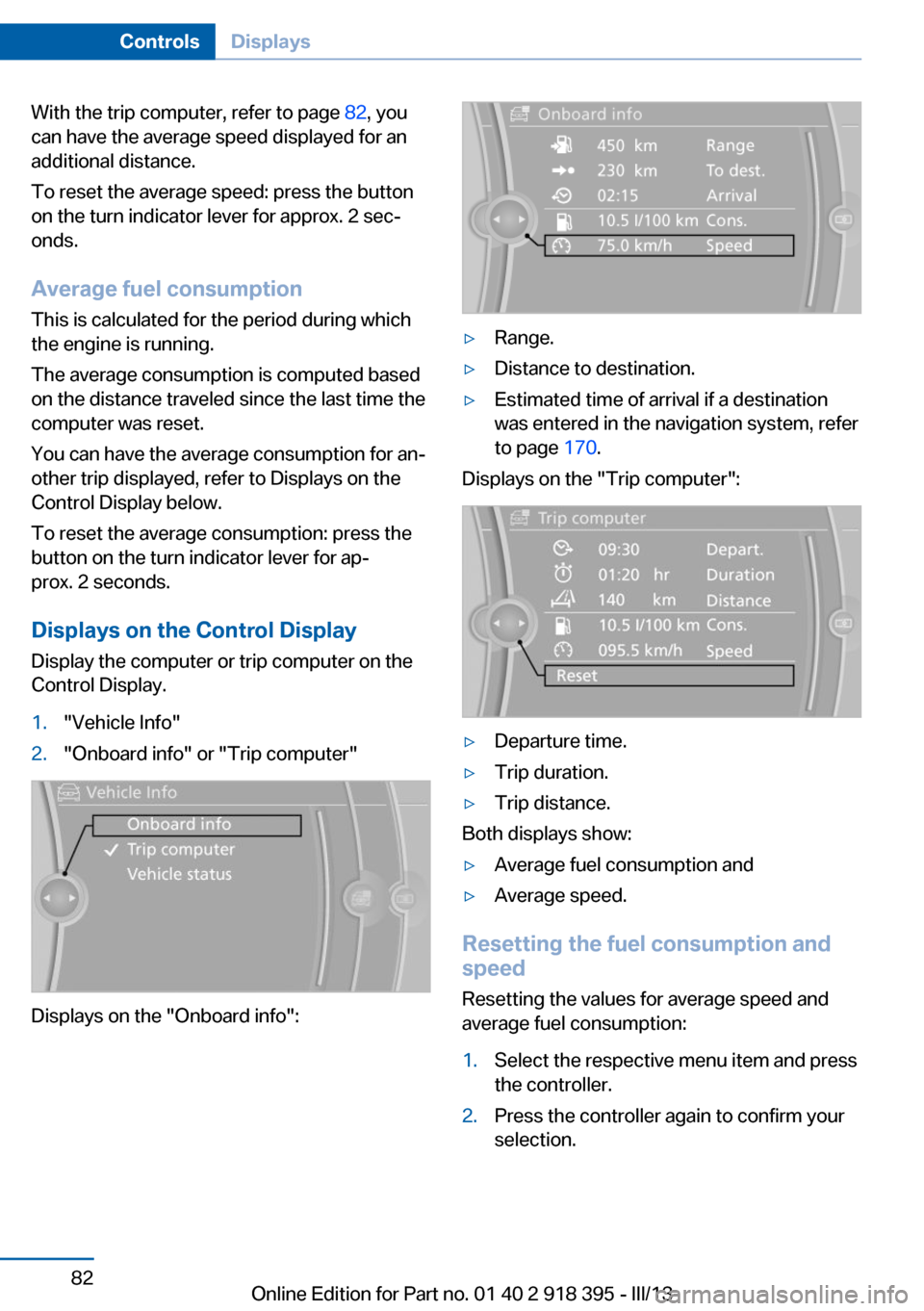
Displays on the Control Display
Display the computer or trip computer on the
Control Display.1."Vehicle Info"2."Onboard info" or "Trip computer"
Displays on the "Onboard info":
▷Range.▷Distance to destination.▷Estimated time of arrival if a destination
was entered in the navigation system, refer
to page 170.
Displays on the "Trip computer":
▷Departure time.▷Trip duration.▷Trip distance.
Both displays show:
▷Average fuel consumption and▷Average speed.
Resetting the fuel consumption and
speed
Resetting the values for average speed and
average fuel consumption:
1.Select the respective menu item and press
the controller.2.Press the controller again to confirm your
selection.Seite 82ControlsDisplays82
Online Edition for Part no. 01 40 2 918 395 - III/13
Page 85 of 345
Check Control
The concept The Check Control monitors vehicle functions
and alerts you to any malfunctions in the sys‐
tems monitored.
A Check Control message consists of indicator and warning lamps in the instrument cluster
and, in some circumstances, an acoustic signal
and text messages at the top of the Control
Display.
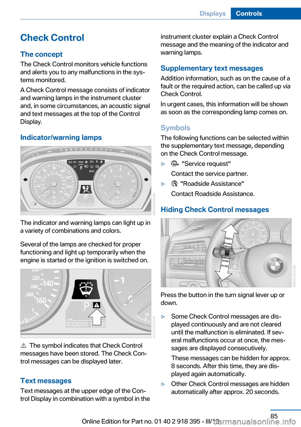
Indicator/warning lamps
The indicator and warning lamps can light up in
a variety of combinations and colors.
Several of the lamps are checked for proper
functioning and light up temporarily when the
engine is started or the ignition is switched on.
The symbol indicates that Check Control
messages have been stored. The Check Con‐
trol messages can be displayed later.
Text messages Text messages at the upper edge of the Con‐
trol Display in combination with a symbol in the
instrument cluster explain a Check Control
message and the meaning of the indicator and
warning lamps.
Supplementary text messages
Addition information, such as on the cause of a
fault or the required action, can be called up via
Check Control.
In urgent cases, this information will be shown
as soon as the corresponding lamp comes on.
Symbols
The following functions can be selected within
the supplementary text message, depending
on the Check Control message.▷ "Service request"
Contact the service partner.▷ "Roadside Assistance"
Contact Roadside Assistance.
Hiding Check Control messages
Press the button in the turn signal lever up or
down.
▷Some Check Control messages are dis‐
played continuously and are not cleared
until the malfunction is eliminated. If sev‐
eral malfunctions occur at once, the mes‐
sages are displayed consecutively.
These messages can be hidden for approx.
8 seconds. After this time, they are dis‐
played again automatically.▷Other Check Control messages are hidden
automatically after approx. 20 seconds.Seite 85DisplaysControls85
Online Edition for Part no. 01 40 2 918 395 - III/13
Page 91 of 345
Headlamp courtesy delay feature
The low beams stay lit for a short while after
the ignition is switched off, if the lamps are
switched off and the headlamp flasher is
switched on.
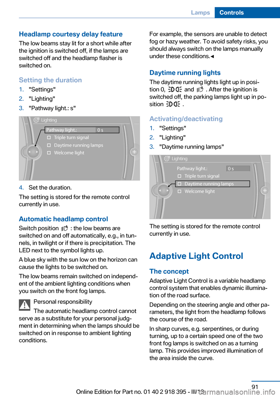
Setting the duration1."Settings"2."Lighting"3."Pathway light.: s"4.Set the duration.
The setting is stored for the remote control
currently in use.
Automatic headlamp control
Switch position
: the low beams are
switched on and off automatically, e.g., in tun‐
nels, in twilight or if there is precipitation. The
LED next to the symbol lights up.
A blue sky with the sun low on the horizon can
cause the lights to be switched on.
The low beams remain switched on independ‐
ent of the ambient lighting conditions when
you switch on the front fog lamps.
Personal responsibility
The automatic headlamp control cannot
serve as a substitute for your personal judg‐
ment in determining when the lamps should be
switched on in response to ambient lighting
conditions.
For example, the sensors are unable to detect
fog or hazy weather. To avoid safety risks, you
should always switch on the lamps manually
under these conditions.◀
Daytime running lights The daytime running lights light up in posi‐
tion 0,
and . After the ignition is
switched off, the parking lamps light up in po‐
sition
.
Activating/deactivating
1."Settings"2."Lighting"3."Daytime running lamps"
The setting is stored for the remote control
currently in use.
Adaptive Light Control
The concept Adaptive Light Control is a variable headlamp
control system that enables dynamic illumina‐
tion of the road surface.
Depending on the steering angle and other pa‐
rameters, the light from the headlamp follows
the course of the road.
In sharp curves, e.g. serpentines, or during
turning, up to a certain speed one of the two
front fog lamps is switched on as a turning
lamp. This provides improved illumination of
the area inside the curve.
Seite 91LampsControls91
Online Edition for Part no. 01 40 2 918 395 - III/13