clock CHEVROLET CAMARO 1967 1.G Chassis User Guide
[x] Cancel search | Manufacturer: CHEVROLET, Model Year: 1967, Model line: CAMARO, Model: CHEVROLET CAMARO 1967 1.GPages: 659, PDF Size: 114.24 MB
Page 170 of 659
FRONT SUSPENSION 3-6
Fig.
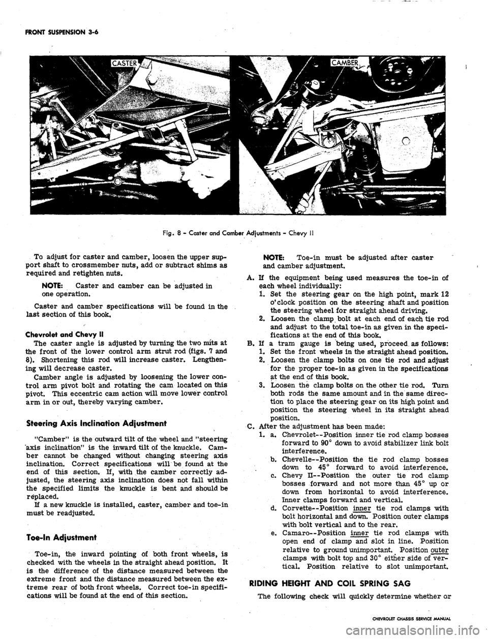
8 - Caster and Camber Adjustments - Chevy
To adjust for caster and camber, loosen the upper sup-
port shaft to crossmember nuts, add or subtract shims as
required and retighten nuts.
NOTE:
Caster and camber can be adjusted in
one operation.
Caster and camber specifications will be found in the
last section of this book.
Chevrolet and Chevy II
The caster angle is adjusted by turning the two niits at
the front of the lower control arm strut rod (figs. 7 and
8).
Shortening this rod will increase caster. Lengthen-
ing will decrease caster.
Camber angle is adjusted by loosening the lower con-
trol arm pivot bolt and rotating the cam located on this
pivot. This eccentric cam action will move lower control
arm in or out, thereby varying camber.
Steering Axis Inclination Adjustment
"Camber" is the outward tilt of the wheel and "steering
axis inclination" is the inward tilt of the knuckle. Cam-
ber cannot be changed without changing steering axis
inclination. Correct specifications willbe found at the
end of this section. If, with the camber correctly ad-
justed, the steering axis inclination does not fall within
the specified limits the knuckle is bent and should be
replaced.
If a new knuckle is installed, caster, camber and toe-in
must be readjusted.
Toe-In Adjustment
Toe-in, the inward pointing of both front wheels, is
checked with the wheels in the straight ahead position. It
is the difference of the distance measured between the
extreme front and the distance measured between the ex-
treme rear of both front wheels. Correct toe-in specifi-
cations will be found at the end of this section.
NOTE:
Toe-in must be adjusted after caster
and camber adjustment.
A. If the equipment being used measures the toe-in of
each wheel individually:
1.
Set the steering gear on the high point, mark 12
o'clock position on the steering shaft and position
the steering wheel for straight ahead driving.
2.
Loosen the clamp bolt at each end of each tie rod
and adjust to the total toe-in as given in the speci-
fications at the end of this book.
B.
If a tram gauge is being used, proceed as follows:
1.
Set the front wheels in the straight ahead position.
2.
Loosen the clamp bolts on one tie rod and adjust
for the proper toe-in as given in the specifications
at the end of this book.
3.
Loosen the clamp bolts on the other tie rod. Turn
both rods the same amount and in the same direc-
tion to place the steering gear on its high point and
position the steering wheel in its straight ahead
position.
C.
After the adjustment has been made:
1.
a. Chevrolet—Position inner tie rod clamp bosses
forward to 90° down to avoid stabilizer link bolt
interference.
b.
Chevelle—Position the tie rod clamp bosses
down to 45?° forward to avoid interference.
c. Chevy II--Position the outer tie rod clamp
bosses forward and not more than 45° up or
down from horizontal to avoid interference.
Inner clamps forward and vertical.
d. Corvette--Position inner tie rod clamps with
bolt horizontal and down. Position outer clamps
with bolt vertical and to the rear.
e. Camaro—Position inner tie rod clamps with
open end of clamp and slot in line. Position
relative to ground unimportant. Position outer
clamps with bolt top and 30° either side of ver-
tical. Position relative to slot unimportant.
RIDING HEIGHT AND COIL SPRING SAG
The following check will quickly determine whether or
CHEVROLET CHASSIS SERVICE MANUAL
Page 217 of 659
REAR SUSPENSION AND DRIVE LINE 4-27
SHIM AND
SERVICE
12
14
Fig.
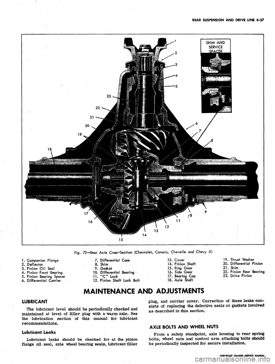
72—Rear Axle Cross-Section (Chevrolet, Camaro, Chevelle and Chevy II)
1.
Companion Flange
2.
Deflector
3. Pinion Oil Seal
4.
Pinion Front Bearing
5. Pinion Bearing Spacer
6. Differential Carrier
LUBRICANT
7. Differential Case
8. Shim
9. Gasket
10.
Differential Bearing
11.
"Clock
12. Pinion Shaft Lock Bolt
13.
Cover
14.
Pinion Shaft
15.
Ring Gear
16.
Side Gear
17.
Bearing Cap
18.
Axle Shaft
19.
Thrust Washer
20.
Differential Pinion
21.
Shim
22.
Pinion Rear Bearing
23.
Drive Pinion
MAINTENANCE AND ADJUSTMENTS
The lubricant level should be periodically checked and
maintained at level of filler plug with a warm axle. See
the lubrication section of this manual for lubricant
recommendations.
Lubricant Leaks
Lubricant leaks should be checked for at the pinion
flange oil seal, axle wheel bearing seals, lubricant-filler
plug, and carrier cover. Correction of these leaks con-
sists of replacing the defective seals or gaskets involved
as described in this section.
AXLE BOLTS AND WHEEL NUTS
From a safety standpoint, axle housing to rear spring
bolts,
wheel nuts and control arm attaching bolts should
be periodically inspected for secure installation.
CHEVROLET CHASSIS SERVICE MANUAL
Page 237 of 659
BRAKES 5-4
RF
3
^ FRONT OF
~ VEHICLE
LF
4
RR
CZZZIZ3
2
LR
1
Fig.
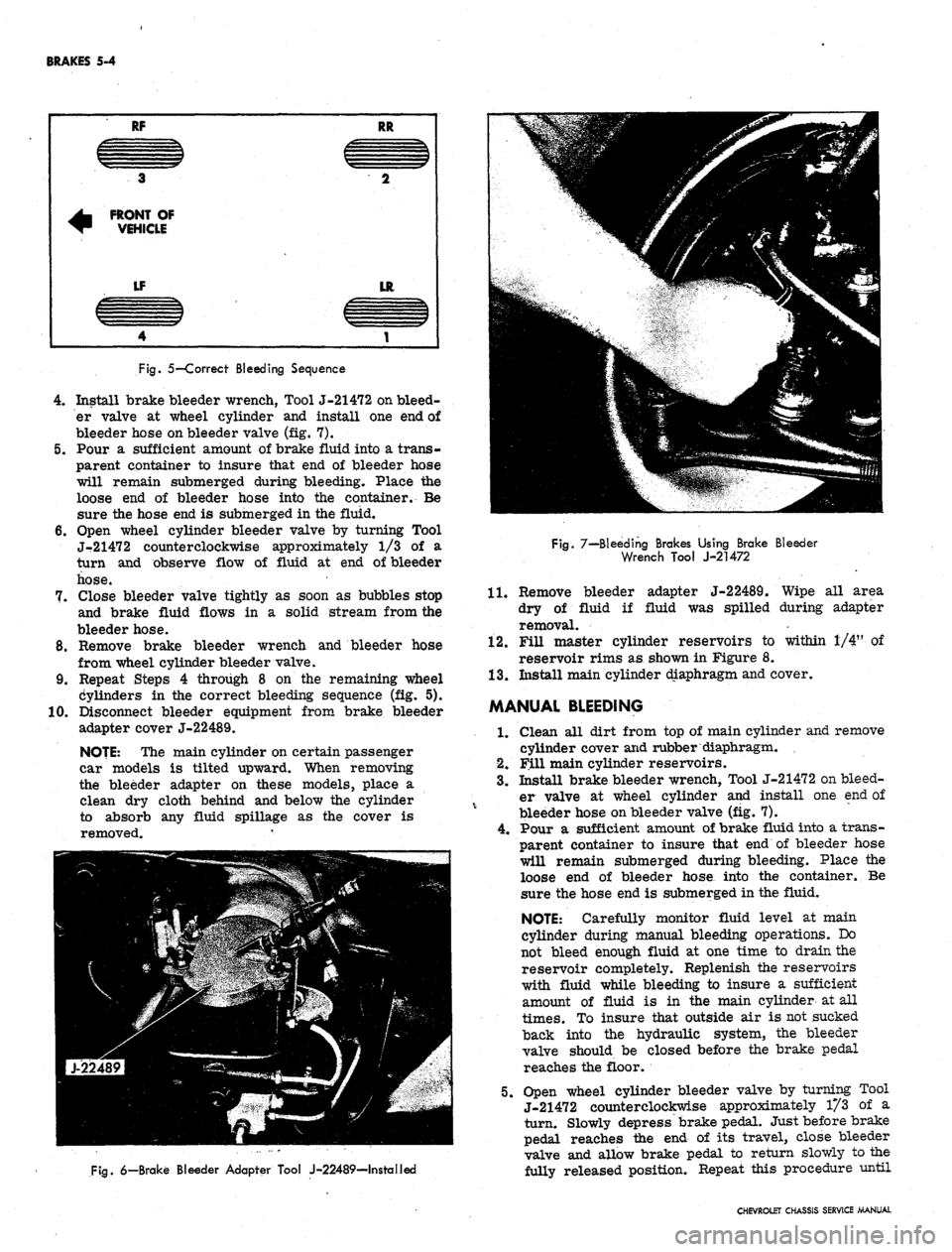
5—Correct Bleeding Sequence
4.
Install brake bleeder wrench, Tool J-21472 on bleed-
er valve at wheel cylinder and install one end of
bleeder hose on bleeder valve (fig. 7).
5.
Pour a sufficient amount of brake fluid into a trans-
parent container to insure that end of bleeder hose
will remain submerged during bleeding. Place the
loose end of bleeder hose into the container. Be
sure the hose end is submerged in the fluid.
6. Open wheel cylinder bleeder valve by turning Tool
J-21472 counterclockwise approximately 1/3 of a
turn and observe flow of fluid at end of bleeder
hose.
7.
Close bleeder valve tightly as soon as bubbles stop
and brake fluid flows in a solid stream from the
bleeder hose.
8. Remove brake bleeder wrench and bleeder hose
from wheel cylinder bleeder valve.
9. Repeat Steps 4 through 8 on the remaining wheel
Cylinders in the correct bleeding sequence (fig. 5).
10.
Disconnect bleeder equipment from brake bleeder
adapter cover J-22489.
NOJE: The main cylinder on certain passenger
car models is tilted upward. When removing
the bleeder adapter on these models, place a
clean dry cloth behind and below the cylinder
to absorb any fluid spillage as the cover is
removed. v
Fig.
7—Bleeding Brakes Using Brake Bleeder
Wrench Tool J-21472
11.
adapter J-22489. Wipe all area
fluid was spilled during adapter
Fig.
6—Brake Bleeder Adapter Tool J-22489—Installed
Remove bleeder
dry of fluid if
removal.
12.
Fill master cylinder reservoirs to within 1/4" of
reservoir rims as shown in Figure 8.
13.
Install main cylinder diaphragm and cover.
MANUAL BLEEDING
1.
Clean all dirt from top of main cylinder and remove
cylinder cover and rubber diaphragm.
2.
Fill main cylinder reservoirs.
3.
Install brake bleeder wrench, Tool J-21472 on bleed-
er valve at wheel cylinder and install one end of
bleeder hose on bleeder valve (fig. 7).
4.
Pour a sufficient amount of brake fluid into a trans-
parent container to insure that end of bleeder hose
will remain submerged during bleeding. Place the
loose end of bleeder hose into the container. Be
sure the hose end is submerged in the fluid.
NOTE: Carefully monitor fluid level at main
cylinder during manual bleeding operations. Do
not bleed enough fluid at one time to drain the
reservoir completely. Replenish the reservoirs
with fluid while bleeding to insure a sufficient
amount of fluid is in the main cylinder at all
times.
To insure that outside air is not sucked
back into the hydraulic system, the bleeder
valve should be closed before the brake pedal
reaches the floor.
5.
Open wheel cylinder bleeder valve by turning Tool
J-21472 counterclockwise approximately 1/3 of a
turn. Slowly depress brake pedal. Just before brake
pedal reaches the end of its travel, close bleeder
valve and allow brake pedal to return slowly to the
fully released position. Repeat this procedure until
CHEVROLET CHASSIS SERVICE MANUAL
Page 255 of 659
BRAKES 5-22
2.
Replace ail push rods and pull back springs.
3.
Connect hose or line to wheel cylinder.
NOTE:
If replacing front wheel cylinder, con-
nect hose and inspect installation as outlined in
"Hydraulic Brake Hose Replacement".
4.
Install drum and wheel.
5. Bleed brakes as outlined in this section.
ANCHOR PIN
Front Wheel
1.
Raise front of vehicle and place on jack stands.
2.
Remove wheel and drum as outlined in this section.
3.
Remove brake shoe pull back springs, link and guide
plate.
4.
Disengage anchor pin lock and remove anchor pin by
turning counterclockwise.
5. Place new lock plate on anchor pin and pass pin
through the hole in flange plate and screw into tapped
hole in spindle support.
6. Torque pin to 130 lb. ft. and lock by peening over
washer tabs.
7. Install brake shoe guide plate, link and pull back
springs.
8. Adjust brakes, install drum and wheel as outlined
in this section. Test brake operation.
Rear Wheel
Two type anchor pins are used in production for the
rear wheels. The riveted type is not serviced and if
failure or damage should occur to either the anchor
pin or flange plate, both parts will have to be replaced
and the threaded type anchor pin used.
Threaded Type
1.
Raise rear of vehicle and place on jack stands,
2.
Remove wheel and drum as outlined in this section.
3.
Remove brake shoe pull back springs, link and guide
plate.
4.
Remove anchor pin retaining nut and washer and
remove pin from flange plate.
5. Position anchor pin to flange plate, install lock
washer and nut, and torque pin to 80 lb. ft.
6. Install brake shoe guide plate, link and pull back
springs.
7. Adjust brakes and install drum and wheel as outlined
in this section.
8. Test brake operation.
BRAKE DRUMS
Front brake drums are the demountable type; that is,
they can be removed without removing the hub. Rear
brake drums are demountable and may be removed
wihtout removing the axle shaft.
A lanced "knock out" area (fig. 34) is provided in
the web of the brake drum for servicing purposes in
the event retracting of the brake shoes is required in
order to remove the drum.
A small screw driver or hooked wire may be inserted
to disengage the automatic adjuster actuating lever so
the star wheel may be turned.
Removal
1.
Raise vehicle and place on jack stand.
2.
Remove wheel and tire assembly, back off brake
adjustment and remove drum.
Inspection and Reconditioning
Whenever brake drums are removed they should be
thoroughly cleaned and inspected for cracks, scores,
deep grooves, and out-of-round. Any of these conditions
must be corrected since they can impair the efficiency
of brake operation and also can cause premature failure
of other parts.
Smooth up any slight scores by polishing with fine
emery cloth. Heavy or extensive scoring will cause
excessive brake lining wear and it will probably be
necessary to rebore in order to true up the braking
surface.
An out-of-round drum makes accurate brake shoe
adjustment impossible and is likely to cause excessive
wear of other parts of brake mechanism due to its
eccentric action.
A drum that is more than .008" out-of-round on the
diameter is unfit for service and should be rebored.
Out-of^round, as well as taper and wear can be ac-
curately measured with an inside micrometer fitted
with proper extension rods.
If drum is to be rebored for use with standard size
brake facings which are worn very little, only enough
metal should be removed to obtain a true smooth braking
surface.
If drum has to be rebored more than .020" over the
standard diameter, it should be rebored to .060" diameter
oversize and the brake facing should be replaced with
.030"
oversize facings.
A brake drum must not be rebored more than .060"
over the maximum standard diameter, since removal
of more metal will effect, dissipation of heat and may
cause distortion of drum. Chevrolet brake facing is
not furnished larger than .030" oversize and this will
not work efficiently in drums bored more than .060"
oversize.
Brake drums may be refinished either by turning or
grinding. Best brake performance is obtained by turning
drums with a very fine feed. To insure maximum lining
life,
the refinished braking surface must be smooth and
free from chatter or tool marks, and run-out must not
exceed .005" total indicator reading.
Cleaning
New brake drums in parts stock are given a light.
coating of rust proofing oil to prevent the formation of
rust on the critical braking surfaces during the time
that the drums are in storage.
This rust proofing oil must be carefully removed
before the drum is placed in service to prevent any
of this oil from getting on the brake shoe facings, which
might cause an extreme brake grab condition.
It is recommended that a suitable volatile, non-toxic,
greaseless type solvent be used to clean the oil from the
braking surface of the new brake drums before they are
•placed in service to insure the cleanest possible surface.
Gasoline or kerosene should not be used as there is
danger that a portion of the diluated oil substance may
be left on the braking surface that may later cause
difficulty.
Installation
1.
Make brake adjustment as outlined in this section.
CHEVROLET CHASSIS SERVICE MANUAL
Page 268 of 659
ENGINE
6-3
(ROUND) Y~~fll^H
CENTRIFUGAL
A ^k
ADVANCE--jflgKpl
MECHANISM
UB|
CAM
KSK^2
LUBRICATOR
VlSMi
REPLACEMENT
^BK
-^ADJUST
SQUARELY
AND
JUST
TOUCHING
LOBE
OF
CAM
/ROTOR
HBB
__
I^BH^F
?
(SOUARE)
^K^ I /—
CAM
jKft^J / LUBRICATOR
H^T^
CAUTION!
QV NEVER
OIL
•L-^
CAM LUBRICATOR-
REPLACE
WICK
WHEN
NECESSARY
LATERAL
MISALIGNMENT
PROPER
LATERAL ALIGNMENT
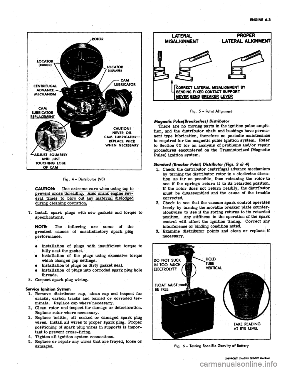
Fig.
4- Distributor (V8)
CAUTION: Use extreme care
-when
using tap to
prevent cross threading. Also crank engine sev-
eral times to blow out any material dislodged
during cleaning operation.
7. Install spark plugs with new gaskets and torque to
specifications.
NOTE:
The following are some of the
greatest causes of unsatisfactory spark plug
performance.
•
Installation of plugs with insufficient torque to
fully seat the gasket.
•
Installation of the plugs using excessive torque
which changes gap settings.
•
Installation of plugs on dirty gasket seal.
•
Installation of plugs into corroded spark plug hole
threads.
8^ Connect spark plug wiring.
Service
Ignition System
1.
Remove distributor cap, clean cap and inspect for
cracks, carbon tracks and burned or corroded ter-
minals. Replace cap where necessary.
2.
Clean rotor and inspect for damage or deterioration.
Replace rotor where necessary.
3.
Replace brittle, oil soaked or damaged spark plug
wires.
Install all wires to proper spark plug. Proper
positioning of spark plug wires in supports is impor-
tant to prevent cross-firing.
4.
Tighten all ignition system connections.
5. Replace or repair any wires that are frayed, loose or
damaged.
Us
CORRECT
LATERAL MISALIGNMENT BY
j BENDING
FIXED CONTACT SUPPORT
[NEVER
BEND BREAKER LEVER
Fig.
5 - Point Alignment
Magnetic
Pulse(Breakerless)
Distributor
There are no moving parts in the ignition pulse ampli-
fier, and the distributor shaft and bushings have perma-
nent type lubrication, therefore no periodic maintenance
is required for the magnetic pulse ignition system. Refer
to Section 6Y for an analysis of problems and/or repair
procedures encountered on the Transistorized (Magnetic
Pulse) ignition system.
Standard
(Breaker Point) Distributor
(Figs.
3 or 4)
1.
Check the distributor centrifugal advance mechanism
by turning the distributor rotor in a clockwise direc-
tion as far as possible, then releasing the rotor to
see if the springs return it to its retarded position.
If the rotor does not return readily, the distributor
must be disassembled and the cause of the trouble
corrected.
2.
Check to see that the vacuum spark control operates
freely by turning the movable breaker plate counter-
clockwise to see if the spring returns to its retarded
position. Any stiffness in the operation of the spark
control will affect the ignition timing. Correct any
interference or binding condition noted.
3.
Examine distributor points and clean or replace if
riecessary.
DO
NOT SUCK
IN
TOO MUCH
ELECTROLYTE
TAKE
READING
AT
EYE LEVEL
Fig.
6 - Testing Specific Gravity of Battery
CHEVROtET
CHASSIS SERVICE MANUAL
Page 272 of 659
ENGINE 6-7
Tune Up should be checked whenever the Air Injection
Reactor System seems to be malfunctioning. Particular
care should be taken in checking items that affect fuel-air
ratio such as the crankcase ventilation system, the car-
buretor and the carburetor air cleaner. Carburetors and
distributors for engines with the Air Injection Reactor
System are designed, particularly, for these engines;
therefore, they must not be interchanged with or replaced
by a carburetor or distributor designed for an engine
without the Air Injection Reactor System.
Choke Adjustment (Fig. 11)
With Remote Choke
1.
Remove air cleaner and check to see that choke
valve and rod move freely.
2.
Disconnect choke r*od at choke lever.
Check choke adjustment as follows:
On all except 275 hp 327 cu. in. engines, hold
choke valve closed and pull rod up against stop. The
top of choke rod end should be 1/2 - 1 rod diameter
4.
5.
above top of hole in choke valve lever.
On 275 hp 327 cu. in. engines, hold choke valve
closed and push rod down against stop on thermostat
bracket. The top of the choke rod should be 1/2 - 1
rod diameter below the top of the hole in the choke
lever.
If necessary, adjust rod length by bending rod at off-
set. (Bend must be such that rod enters choke lever
hole freely and squarely.)
Connect rod at choke lever and install air cleaner.
3.
With Manual
Choke
1.
Remove air cleaner.
2.
Push hand choke knob in to within 1/8" of instrument
panel.
3.
Loosen choke cable at carburetor bracket and adjust
cable through the clip until the choke valve is wide
open.
4.
Tighten cable clamp at carburetor bracket and check
operation of choke valve to ensure full closed and
wide open positions.
INSTRUMENT CHECK-OUT
Instrument Hook Up
Connect vacuum gauge, dwell meter, tachometer and
timing light as recommended by the manufacturer of the
equipment being used.
Check and Adjust Dwell
1.
Start engine then ch^ck ignition dwell.
.2.
If dwell is not within specifications, adjust dwell as
follows:
V8 ENGINES
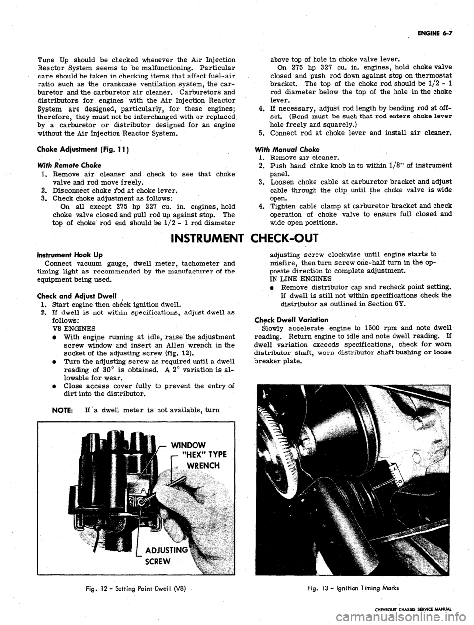
• With engine running at idle, raise the adjustment
screw window-and insert an Allen wrench in the
socket of the adjusting screw (fig. 12).
• Turn the adjusting screw as required until a dwell
reading of 30° is obtained. A 2° variation is al-
lowable for wear.
• Close access cover fully to prevent the entry of
dirt into the distributor.
NOTE: If a dwell meter is not available, turn
adjusting screw clockwise until engine starts to
misfire, then turn screw one-half turn in the op-
posite direction to complete adjustment.
IN LINE ENGINES
• Remove distributor cap and recheck point setting.
If dwell is still not within specifications check the
distributor as outlined in Section 6Y.
Check Dwell Variation
Slowly accelerate engine to 1500 rpm and note dwell
reading. Return engine to idle and note dwell reading. If
dwell variation exceeds specifications, check for worn
distributor shaft, worn distributor shaft bushing or loose
breaker plate.
WINDOW
"HEX" TYPE
WRENCH
Fig.
12 - Setting Point Dwell (V8)
Fig.
13 - Ignition Timing Marks
CHEVROLET CHASSIS SERVICE MANUAL
Page 282 of 659
ENGINE 6-17
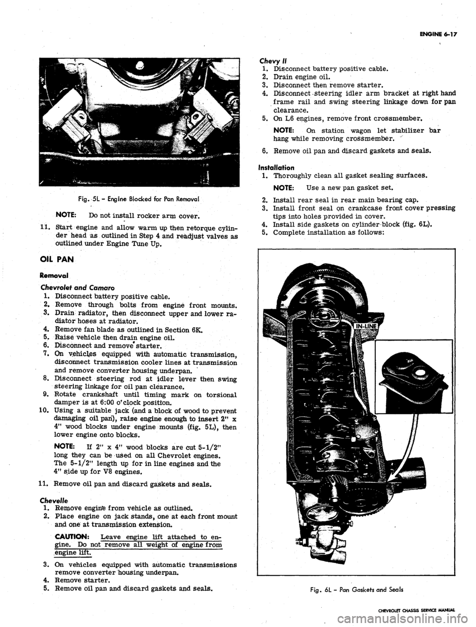
Fig.
5L
-
Engine Blocked for Pan Removal
NOTE: Do not install rocker arm cover.
11.
Start engine and allow warm up then retorque cylin-
der head
as
outlined in Step 4 and readjust valves as
outlined under Engine Tune Up.
OIL PAN
Removal
Chevrolet
and Camaro
1.
Disconnect battery positive cable.
2.
Remove through bolts from engine front mounts.
3.
Drain radiator, then disconnect upper and lower ra-
diator hoses at radiator.
4.
Remove fan blade as outlined in Section 6K.
5.
Raise vehicle then drain engine oil.
6. Disconnect and remove* starter.
7.
On
vehicles equipped with automatic transmission,
disconnect transmission cooler lines at transmission
and remove converter housing underpan.
8. Disconnect steering
rod at
idler lever then swing
steering linkage for oil pan clearance.
9. Rotate crankshaft until timing mark
on
torsional
damper is at 6:00 o'clock position.
10.
Using
a
suitable jack (and a block of wood to prevent
damaging oil pan), raise engine enough to insert 2"
x
4"
wood blocks under engine mounts (fig. 5L), then
lower engine onto blocks.
NOTE:
If
2"
x
4" wood blocks are cut 5-1/2"
long they can be used on all Chevrolet engines.
The 5-1/2" length up for in line engines and the
4"
side up for V8 engines.
11.
Remove oil pan and discard gaskets and seals.
Cfievel/e
1.
Remove enginfe from vehicle as outlined.
2.
Place engine on jack stands, one at each front mount
and one at transmission extension.
CAUTION: Leave engine lift attached
to
en-
gine.
Do not remove all weight
of
engine from
engine lift.
3.
On
vehicles equipped with automatic transmissions
remove converter housing underpan.
4.
Remove starter.
5.
Remove oil pan and discard gaskets and seals.
Chevy//
1.
Disconnect battery positive cable.
2.
Drain engine oil.
3.
Disconnect then remove starter.
4.
Disconnect-steering idler arm bracket at right hand
frame rail and swing steering linkage down for pan
clearance.
5.
On L6 engines, remove front crossmember.
NOTE:
On
station wagon
let
stabilizer
bar
hang while removing crossmember.
"
6. Remove oil pan and discard gaskets and seals.
Installation
1.
Thoroughly clean all gasket sealing surfaces.
NOTE: Use
a
new pan gasket set.
2.
Install rear seal in rear main bearing cap.
3.
Install front Seal on crankcase front cover pressing
tips into holes provided in cover.
4.
Install side gaskets on cylinder block (fig. 6L).
5.
Complete installation as follows:
Life
1
i
If ^
jfp^;.^3p
>\~^^ \s3^^r' -'••'•'-^^Hll
|^=-5p|:*iil^
mm
Fig.
6L
-
Pan Gaskets and Seals
CHEVROLET CHASSIS SERVICE MANUAL
Page 283 of 659
ENGINE 6-18
NOTE:
Bolts into crankcase cover should be
installed last. They are installed at an angle
and holes line up after rest of pan bolts are
snugged up.
Chevrolet and Camaro
a. If crankshaft was rotated while pan was off, place
timing mark at 6:00 o'clock position.
b.
Install oil pan and torque bolts to specifications.
c. Using a suitable jack (and a block of wood to prevent
damaging oil pan) raise engine enough to remove 2" x
4"
wood blocks, then lower engine.
d. On vehicles equipped with automatic transmission
install converter housing underpan, then connect
transmission cooler lines.
e. Install and connect starter.
f. Lower vehicle and install fan blades as outlined in
Section 6K.
g. Connect upper and lower radiator hoses.
h. Install through bolts in engine front mounts.
i. Connect battery positive cable.
j.
Fill radiator with coolant and fill engine with oil,
then start engine and check for leaks.
Chevelie
* a. Install oil pan and torque bolts to specifications.
b.
On vehicles equipped with automatic transmission,
install converter housing underpan.
c. Install starter.
d. Install engine as outlined.
Chevy II
a. Install oil pan and torque bolts to specifications.
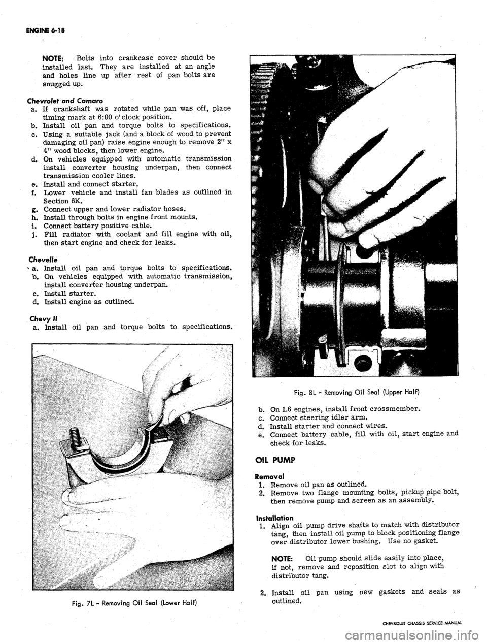
Fig.
7L- Removing Oil Sea! (Lower Half)
Fig.
8L - Removing Oil Seal (Upper Half)
b.
On L6 engines, install front crossmember.
c. Connect steering idler arm.
d. Install starter and connect wires.
e. Connect battery cable, fill with oil, start engine and
check for leaks.
OIL PUMP
Removal
1.
Remove oil pan as outlined.
2.
Remove two flange mounting bolts, pickup pipe bolt,
then remove pump and screen as an assembly.
Installation
1.
Align oil pump drive shafts to match with distributor
tang, then install oil pump to block positioning flange
over distributor lower bushing. Use no gasket.
NOTE:
Oil pump should slide easily into place,
if not, remove and reposition slot to align with
distributor tang.
2.
Install oil pan using new gaskets and seals as
outlined.
CHEVROLET CHASSIS SERVICE MANUAL
Page 293 of 659
ENGINE 6-28
damper comes near the "0" mark on the front
cover.
11
the valves are not moving, the engine is
in the number 1 firing position. If the valves
move as the mark comes up to the timing tab, the
.
engine is in number 6 firing position and crank-
shaft should be rotated one more revolution to
reach the number 1 position,
b.
Valve adjustment is made by backing off the ad-
justing nut (rocker arm stud nut) until there is
play in the push rod and then tighten nut to just
remove all push rod to rocker arm clearance.
' this may be determined by rotating push rod with
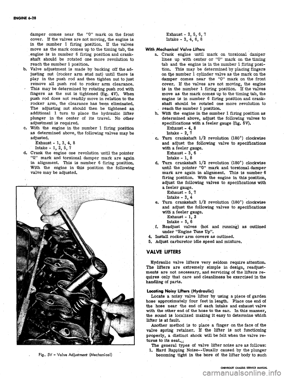
fingers as the nut is tightened (fig. 4
V).
When
push rod does not readily move in relation to the
rocker arm, the clearance has been eliminated.
The adjusting nut should then be tightened an
additional 1 turn to place the hydraulic lifter
plunger in the center of its travel. No other
adjustment is required.
c. With the engine in the number 1 firing position
as determined above, the following valves may be
adjusted.
Exhaust - 1, 3, 4, 8
Intake - 1, 2, 5, 7
d. Crank the engine one revolution until the pointer
"(X" mark and torsional damper mark are again
in alignment. This is number 6 firing position.
With the engine in this position the following
valve may be adjusted.
Fig.
5V - Valve Adjustment (Mechanical)
Exhaust - 2, 5, 6, 7
Intake
-•
3, 4, 6, 8
With Mechanical Valve
Lifters
a. Crank engine until mark on torsional damper
lines up with center or "0" mark on the timing
tab and the engine is in the number 1 firing posi-
tion. This may be determined by placing fingers
on t£e number 1 cylinder valve as the mark on the
damper comes near the n0" mark on the front
cover. If the valves are not moving, the engine
is in the number 1 firing position. If the valves
move as the mark comes up to the timing tab, the
engine is in number 6 firing position and crank-
shaft should be rotated one more revolution to
reach the number 1 position.
b.
With the engine in the number 1 firing position as
determined above, adjust the following valves to
specifications with a feeler gauge (fig. 5V).
Exhaust - 4, 8
Intake - 2, 7. .
c. Turn crankshaft 1/2 revolution (180°) clockwise
and adjust the following valve to specifications
with a feeler gauge.
Exhaust -3,6
Intake - 1, 8
d. Turn crankshaft 1/2 revolution (180°) clockwise
until the pointer "0" mark and torsional-damper
mark are again in alignment. This is number 6
firing position. With the engine in this position,
adjust the following valves to specifications with
a feeler gauge.
Exhaust -5,7
Intake - 3, 4
e. Turn crankshaft 1/2 revolution (180°) clockwise
and adjust the following valves to specifications
with a feeler gauge.
Exhaust - 1, 2
Intake - 5, 6
f. Readjust valves (hot and running) as outlined
under "Engine Tune Up".
4.
Install rocker arm covers as outlined.
5.
Adjust carburetor idle speed and mixture.
VALVE LIFTERS
Hydraulic valve lifters very seldom require attention;
The lifters are extremely simple in design, readjust-
ments are not necessary, and servicing of the lifters re-
quires only that care and cleanliness be exercised in the
handling of parts.
Locating Noisy Lifters (Hydraulic)
Locate a noisy valve lifter by using a piece of garden
hose approximately four feet in length. Place one end of
the hose near the end of each intake and exhaust valve
with the other end of the hose to the ear. In this manner,
the sound is localized making it easy to determine which
lifter is at fault.
Another method is to place a finger on the face of the
valve spring retainer. If the lifter is not functioning
properly, a distinct shock will be felt when the valve re-
turns to its seat.-*
The general types of valve lifter noise are as follows:
1.
Hard Rapping Noise—Usually caused by the plunger
becoming tight in the bore of the lifter body to such
CHEVROLET CHASSIS SERVICE MANUAL
Page 295 of 659
ENGINE 6-30
c". Install the valve locks and release the compres-
sor tool making sure the locks seat properly in
the upper groove of the valve stem.
NOTE: Grease may be used to hold the locks
in place while releasing the compressor tool.
396 and 427
cu.
in.
Engines
a. Install new valve stem oil seal (coated with oil)
in position over valve guide.
b.
Set the valve spring and damper and valve cap in
place.
c. Compress the spring with Tool J-5892 and install
the valve locks, then release the compressor tool,
making sure the locks seat properly in the groove
of the valve stem.
NOTE: Grease may be used to hold the locks
in place while releasing the compressor tool.
7.
Install spark ,plug, using a new gasket, and torque to
specifications. -
8. Install and adjust valve mechanism as outlined.
CYLINDER HEAD ASSEMBLY
Removal
1.
Remove intake manifold as outlined.
2.
Remove exhaust manifolds as outlined.
3.
Remove valve mechanism as outlined.
4.
Drain cooling system (block).
5.
Remove cylinder head bolts, cylinder head and gas-
ket. Place cylinder head on two blocks of wood to
prevent damage.
Installation
CAUTION: The gasket surfaces on both the
head and the block must be clean of any foreign
ttter and free of nicks or heavy scratches.
Under bolt threads in the block and threads on
Pie cylinder head bolt must be cleaned. (Dirt
will affect bolt torqueT)
1.
On engines using a STEEL gasket, coat both sides of
a new gasket with a good sealer, spread the sealer
thin and even. One method of applying the sealer that
will assure the proper- coat is with the use of a paint
roller. Too much sealer may hold the beads of the
gasket away from the head or block.
CAUTION: Use no sealer on engines using a
composition STEEL ASBESTOS gasket.
2.
Place the gasket in position over the dowel pins with
the bead up.
3.
Carefully guide cylinder head into place over dowel
pins and gasket.
4.
Coat threads of cylinder head bolts with sealing
compound and install finger tight.
5.
Tighten cylinder head bolts a little at a time in the
sequence shown on the torque sequence chart until
the specified torque is reached.
6. Install the exhaust manifold as outlined.
7.
Install the intake manifold as outlined.
8. Install and adjust the valve mechanism as outlined.
OIL
PAN
Removal
Chevrolet
and Camaro
1.
Disconnect battery positive cable.
2.
Disconnect distributor cap from distributor (to pr-e-
vent breaking distributor cap when engine is raised).
3.
Drain radiator, then disconnect lower radiator hose
at water pump and remove oil dip stick and tube
(where necessary). '
4.
Remove fan blade.
5.
Raise vehicle then drain engine oil;
6. Remove through bolts from engine front mounts.
Disconnect and remove starter.
7.
On vehicles equipped with automatic transmissions,
remove converter housing underpan.
8. Disconnect steering rod at idler lever then swing
steering linkage 4pwn for oil pan clearance.
9. Rotate crankshaft untii timing mark on torsional
damper is at 6:00 o'clock position.
10.
Using a suitable jack, and a block of wood to prevent
damaging oil pan, raise engine "enough to insert 2" x
4"
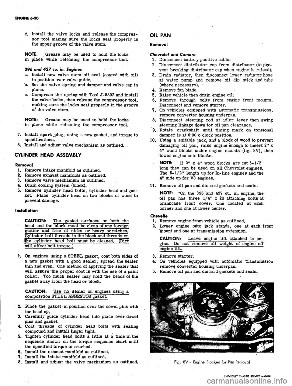
wood blocks under engine mounts (fig. 8V), then
lower engine onto blocks.
NOTE: If 2" x 4" wood blocks are cut 5-1/2"
long they can be used on all Chevrolet engines.
The 5-1/2" length up for In-line engines and the
4"
side up for V8 engines.
11.
Remove oil pan and discard gaskets and seals.
NOTE: -On the 396 and 427 cu. in. engine, the
oil pan has three 1/4" x 20 attaching bolts at ,
crankcase front cover. One located at each
corner and one at lower center.
Chevelle
1.
Remove engine from vehicle as outlined.
2.
Lower engine onto jack stands, one at each front
Tnaount and one at transmission extension.
CAUTION: Leave engine lift attached to en-
gine.
Do not remove all weight of engine off
engine lifET
3.
Remove starter.
4.
On vehicles equipped with automatic transmission
remove converter housing underpan.
5.
Remove oil pan and discard gaskets and seals.
Fig.
8V - Engine Blocked for Pan Removal
CHEVROLET CHASSIS SERVICE MANUAL