diagram CHEVROLET CAMARO 1967 1.G Chassis User Guide
[x] Cancel search | Manufacturer: CHEVROLET, Model Year: 1967, Model line: CAMARO, Model: CHEVROLET CAMARO 1967 1.GPages: 659, PDF Size: 114.24 MB
Page 61 of 659

HEATER AND AIR CONDITIONING 1A-38
HIGH BLOWER
DELAY RELAY
O) MASTER AND
HIGH BLOWER
DELAY RELAY
GROUND
Fig.
49A-Comfortron Wiring Diagram-Underhood
CHEVROLET CHASSIS SERVICE AAANUAL
Page 62 of 659
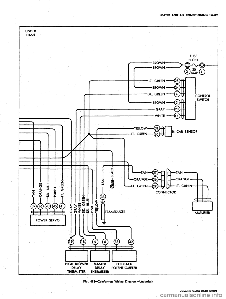
HEATER AND AIR CONDITIONING 1A-39
BROWN
BROWN
LT.
GREEN
BROWN
DK. GREEN
CONTROL
SWITCH
N-CAR
SENSOR
"—ORANGE—(36
[y—LT. GREEN
*)WWWW 55|—jg
TRANSDUCER
POWER SERVO
HIGH BLOWER MASTER FEEDBACK
DELAY DELAY POTENTIOMETER
THERMISTER THERMISTER
Fig.
49B-Comforrron Wiring Diagram-Underdash
CHEVROLET CHASSIS SERVICE AAANUAL
Page 63 of 659
HEATER AND AIR CONDITIONING 1A-40
THERAAAL VACUUM
VALVE
TO ENGINE
VACUUM
SOURCE
VACUUM STORAGE
TANK
OUTSIDE AIR
DIAPHRAGM
MODE
DIAPHRAGM
VACUUM
RELAY
BLACK
DEFOG-DEICE
DIAPHRAGM
GREEN
BLACKj ||
|
BROWN
CONTROL
VALVE
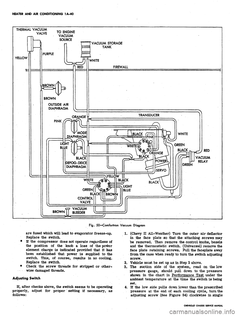
Fig.
50—Comfortron Vacuum Diagram
are fused which will lead to evaporator freeze-up.
Replace the switch.
• If the compressor does not operate regardless of
the position of the knob a loss of the power
element charge is indicated provided that it has
been established that power is supplied to the
switch. This, of course, results in no cooling.
Replace the switch.
• Check the screw threads for stripped or other-
wise damaged threads.
Adjusting Switch
H, after checks above, the switch seems to be operating
properly,
follows:
adjust for proper setting if necessary, as
1.
(Chevy II All-Weather) Turn the outer air deflector
in the face plate so that the attaching screws may
be removed; Then remove the control knobs, bezels
and the thermostatic switch. (Universal) remove the
face plate retaining screws. Pull the faceplate away
from the case when ready to turn the switch adjusting
screw.
2.
Vehicle must be set up as in Step 2 above.
3.
The suction side of the system, read on the low
pressure gauge, should pull down to the pressure
shown in the chart in Performance Test under the
ambient temperature at the time the switch is being
set.
4.
If the low side pulls down lower than the prescribed
pressure at the end of each cooling cycle, turn the
adjusting screw (See Figure 54) clockwise in single
CHEVROLET CHASSIS SERVICE MANUAL
Page 101 of 659

HEATER AND AIR CONDITIONING 1A-78
WIRING DIAGRAMS
Blower
Motor
Resistor
•
Asm
EVAPORATOR—v
ASM.
\
-Diode
(Arc I
suppressor)
^\
16B
—>
-COMPRESSOR
Clutch Coil
•To battery positive
(+) terminal
No vacuum
in hose
#3
Blower
intake
air
Outside
air entry
Valve
by vacuum
in
hose
#3
Valve
normally
closed (spring
held)
Inside
car
air
(Recirc.)
AIR INLET
VALVE
POSITION:
Outside
air
intake
Recirc. air'intake
CONTROL ASM
TEMP CONTROL LEVER
(Operates temp valve
cable
&
equipment
in
chart shown below)
Compressor
Sw.
(Normally closed
Temp valve
begins
to
open
valveV
cable
arm
•Fan Speed Selector Switch
Switch
lever
position
Off
Low
Med
High
Contacts
made
B
to
None
BtoL
B to L
&
M
B to
L
& H
Fan
speed
Low
Low
Med
High
Resistance
in series with
Bio Motor
Hi
Rl
(RiR2)/(Rl+R2)
None
•Blower switch contacts must
be
dosed
before
fan
switch will
be
operable.
COLD
(O.
A.)
COLD a.A.)
Blower
H
y—low
switch
M/
-med
(Norm,
closed
contacts)
Fan speed switch
(See chart
at
left)
To vacuum,
tank
EXTENSION—vy
Horn relay "Bat" WIRE
ASM
X
harness
terminal
V
.**-__.. ;_
1 I panel
Legend:
___. —
Production wiring
Wire
is
part
of
equip.
•—————* Air
conditioning
wrg.
| i
T Agn. sw.
accsy
I term.
I
Temp
Control
Lever
Position
OFF
VENT.
COLD(I.A.)
COLEKO.AJ
HOT
Blower
(Master)
switch
contacts
Open
Closed
Closed
Closed
Closed
Vac switch
connects
vac source
to hose
#
#2
#2
&
#3
None
#3
#2
&
#3
Compressor
switch
contacts:
Open
Open
Closed
Closed
Open
Blower
intake
air
Outside
car air
intake used
Inside
car air
recirculated
Outside
car air
intake used
.Outside
car air
intake used
Fig. 114—Chevrolet—Four-Season Wiring Diagram
CHEVROLET CHASSIS SERVICE MANUAL
Page 102 of 659
HEATER
AND AIR CONDITIONING IA-79
BAT.
CABLE
ASM
A/C
wrg fwd of
dash
exc
bat.
cables,
ext
wire
&
compressor
grd
wire
is
part
of engine wiring harness.
"COMPRESSOR"
SW:
"OFF" POSN
"ON"
POSN
RELAY
ASM
/-DASH
/
PANEL
RESISTOR
ASM
LUTCH
COIL
:OMI
GRD
WIRE
ASM
MPRESSOR
BAT.
TERM
ON START
MTR SOL
EXTENSION WIRE ASM
._
J
J
^-CONTROL
SW
CONTACTS
B TO NONE
BTOL
BTOL&M
BTOL6H
•IGN SW ACCSY TERM.
A/C wrg
to
rear
of
dash
of
inst pnl harness.
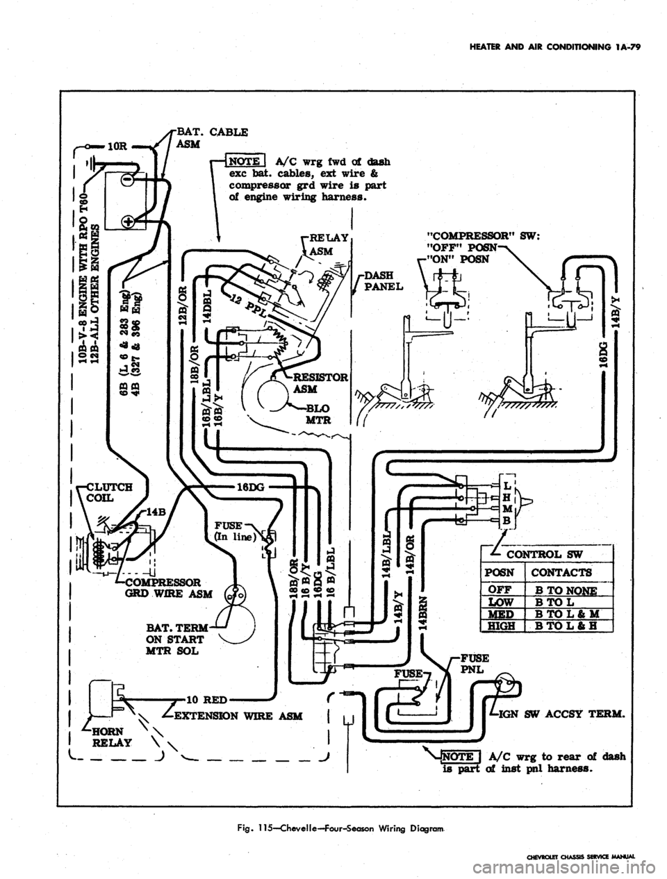
Fig.
115—CheveIle—Four-Season Wiring Diagram
CHEVROLET
CHASSIS SERVICE MANUAL
Page 103 of 659

HEATER
AND AIR
CONDITIONING
1A-80
EVAPORATOR ASM.
Blower
Motor
INSIDE VALVE
(Normally closed
-spring held)
PLENUM VALVE
(Normally open
-spring held)
Actuator
(Vacuum
operated)
Inside car air (Recirc*
CONTROL ASM
TEMP CONTROL LEVER
•(Operates temp valve
cable
&
equipment in
hart shown below)
Temp valve
begins to
16DG
Fuse (In-line^
COMPRESSOR
Clutch Coil DASH-
PANEL
•Fan Speed Selector Switch
Switch
lever
position
Off
Low
"HeST
High
Contacts
B to
None
BtoL
B to L b U
BtoL&H
Fan
speed
Low
Low
Med
High
Resistance
in series with
Bio Motor
Rl
Rl
RlR2)/(Rl+R2)
None
•Blower switch contacts must be closed
before fan switch will be operable.
-To battery positive
(-0 terminal
•
Horn relay
terminal"
"Batf
To vacuum
tank
EXTENSION
WIRE
ASM
(Normally closed
contacts-*vac
operated)
7
*- Fan speed switch
(See chart at left)
•/-Wire is
\ part of
I inst panel
harness
Legend:
— Production wiring
————
Wire Is part of equip.
•mmmmmmmmmmmmmm*
AIT
Conditioning
WTg*
Temp
Control
Lever
Position
OFF
VENT
COLD
a.A.)
COLD
(O.A.)
HOT
Blower
(Master)
switch
contacts
Open
Closed
Closed
Closed
Closed
Vac switch
connects
vac source
to hose #
#2
&
#3
#2
#3
None
#2
Compressor
switch
contacts^
Open
Open
Closed
Closed
Open
Blower
intake air
Outside car air
intake used
Inside car air
recir culated
Outside car air
intake used
Outside car air
intake used
Fig.
116—Camaro—Four-Season Wiring Diagram
CHEVROLET CHASSIS SERVICE
Page 104 of 659
HEATER AND AIR CONDITIONING 1A-81
HORN RELAY
r
CONN.-
14 BROWN
(TO FUSE
PANEL)
BATTERY
1
—I ^ COMPR
ESSOR
DASH y
V-^ PANEL \
GROMMET—%
1 \
_ J~ ") "^
>14 BLACK/RED STRIPE-
FUSE .20 AMP.
•WIRE ASM. BLOWER-
MOTOR
14 BLACK 1
IGNITION SWITCH1
(ACCESSORY
TERMINAL)
CONTROL SWITCH
-RESISTOR
CONN.
•14 TAN
•16 BLACK
LIGHT BLUE STRIPE
•THERMOSTAT CONTROL
EVAPORATOR & BLOWER ASM.
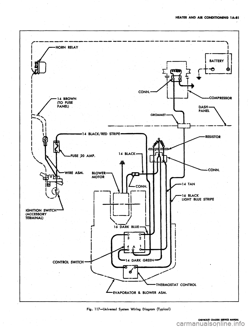
Fig.
117—Universal System Wiring Diagram (Typical)
CHEVROLET CHASSI
Page 105 of 659
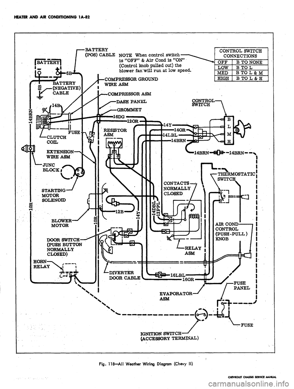
HEATER AND AIR CONDITIONING 1A-82
•BATTERY
(POS)
CABLE
NOTE
When
control
switch*
is !TOFF"
&
Air
Cond
is
"ON"
(Control
knob
pulled
but) the
blower
fan'will
run at low
speed.
CONTROL
SWITCH
CONNECTIONS
OFF
LOW
MED
HIGH
B
TO
NONE
B
TO L
BTOL&M
B
TO L
&
H
COMPRESSOR
GROUND
WIRE
ASM
BATTERY
(NEGATIVE)
CABLE
COMPRESSOR
ASM
DASHPAJSTEL
GROMMET
16DG
CONTROL
SWITCH
RESISTOR
ASM
14LBL
14BRN
CLUTCH
COIL
EXTENSION
WIRE
ASM
-14BRN--N
JUNC
BLOCKi
OSTATIC
SWITCH
CONTACTS
NORMALLY
CLOSED
STARTING
MOTOR
SOLENOID
BLOWER
MOTOR
AIR
COND
CONTROL
(PUSH-PULL)
KNOB
DOOR
SWITCH
(PUSH
BUTTON
NORMALLY
CLOSED)
RELAY
ASM
HORN
RELAY
DIVERTER
DOOR CABLE
FUSE
PANEL
EVAPORATOR
ASM
IGNITION SWITCH-
ACCESSORY TERMINAL)
Fig. 118—All Weather Wiring Diagram (Chevy II)
CHEVROLET CHASSIS SERVICE MANUAL
Page 106 of 659
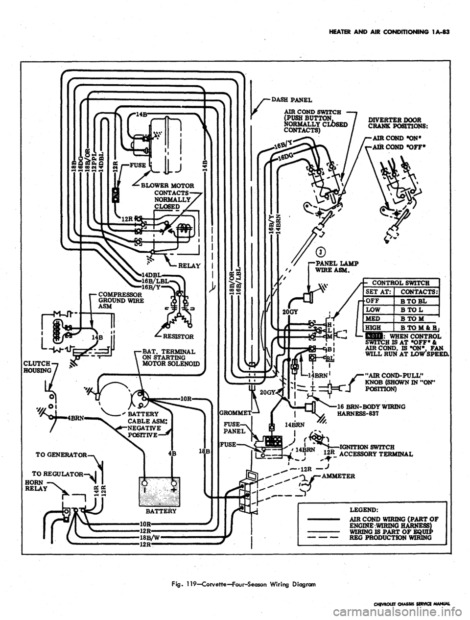
HEATER AND AIR CONDITIONING 1A-83
DIVERTER DOOR
CRANK POSITIONS:
AIR COND "ON"
AIR COND "OFF*
AIR COND SWITCH
(PUSH BUTTON,
NORMALLY CLOSED
CONTACTS)
BLOWER MOTOR
CONTACTS
NORMALLY
4D
16
16B/Y
COMPRESSOR
GROUND WIRE
ASM
BAT.
TERMINAL
ON STARTING
MOTOR SOLENOID
' BATTERY
CABLE ASM:
NEGATIVE
POSITIVE—*
- CONTROL SWITCH
SET AT:
•OFF
LOW
MED
HIGH
CONTACTS:
BTOBL
BTOL
BTOM
BT0M6B,
CLUTCH
HOUSING
liOli: WHEN CONTROL
SWITCH IS AT "OFF" &
AIR COND. IS "ON", FAN
WILL RUN AT LOW SPEED.
"AIR COND-PULL"
KNOB (SHOWN IN "ON"
POSITION)
TO REGULATOR
HORN
RELAY
16 BRN-BODY WIRING
HARNESS-837
14BRN
I
^
IA^RN
* IGNITION SWITCH
« 12R ACCESSORY TERMINAL
12R f
AMMETER
LEGEND:
AIR COND WIRING (PART OF
ENGINE WIRING HARNESS)
WIRING IS PART OF EQUIP
REG PRODUCTION WIRING
Fig.
119—Corvette—Four-Season Wiring Diagram
CHEVROLET CHASSIS SERVICE MANUAL
Page 333 of 659
ENGINE-ELECTRICAL 6Y-8
1
FIELD RELAY^I^p2
"LATCH"
^PFN?^
"P1
TERMINAL
JyJvJCTl^
NO. 2 TERMINAD^5^^^«
NO.
3 TERMINAL ^S5«£
NO.
4 TERMINAL ^^^
m
# / VOLTAGE
¥ REGULATOR
1
ACCESS PLUG TO
VOLTAGE ADJUSTMENT
No 4 TERMINAL
Double Contact
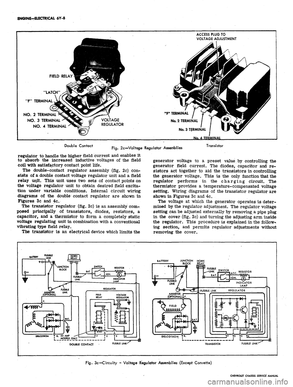
Fig.
2c—Voltage Regulator Assemblies
Transistor
regulator to handle the higher field current and enables it
to absorb the increased inductive voltages of the field
coil with satisfactory contact point life.
The double-contact regulator assembly (fig. 2c) con-
sists of a double contact voltage regulator unit and a field
relay unit. This unit uses two sets of contact points on
the voltage regulator unit to obtain desired field excita-
tion under variable conditions. Internal circuit wiring
diagrams of the double contact regulator are shown in
Figures 3c and 4c.
The transistor regulator (fig. 2c) is an assembly com-
posed principally of transistors, diodes, resistors, a
capacitor, and a thermistor to form a completely static
voltage regulating unit in combination with a conventional
vibrating type field relay.
The transistor is an electrical device which limits the
generator voltage to a preset value by controlling the
generator field current. The diodes, capacitor and re-
sistors act together to aid the transistors in controlling
the generator voltage. This is the only function that the
regulator performs in the charging circuit. The
thermistor provides a temperature-compensated voltage
setting. Wiring diagrams of the transistor regulator are
shown in Figures 3c and 4c.
The voltage at which the generator operates is deter-
mined by the regulator adjustment. The regulator voltage
setting can be adjusted externally by removing a pipe plug
in the cover (fig. 2c) and turning the adjusting arm inside
the regulator. This procedure is explained in the followr
ing section, and permits regulator adjustments without
removing the cover.
FUSIBLE
DOUBLE CONTACT
FUSIBLE LINK-^
JUNCTION HORN
BLOCK RELAY
RESISTOR
Q FIELD Q>
DELCOTRON TR-
TRANSISTOR
FUSIBLE LINK-
Fig.
3c-Circuity - Voltage Regulator Assemblies (Except Corvette)
CHEVROLET CHASSIS SERVICE MANUAL