radio CHEVROLET CAMARO 1967 1.G Chassis User Guide
[x] Cancel search | Manufacturer: CHEVROLET, Model Year: 1967, Model line: CAMARO, Model: CHEVROLET CAMARO 1967 1.GPages: 659, PDF Size: 114.24 MB
Page 355 of 659

ENGINE-ELECTRICAL-6Y-30
Fig.
2 li—Removing Ignition Switch Nut
4.
Remove heater and/or A/C control panel assembly
retaining screws and push panel assembly from
console.
NOTE: If interference between control panel
and radio is encountered, loosen radio retaining
nuts.
5.
Remove radio control knobs, bezels and retaining
nuts.
6. Disconnect radio wiring harness and antenna lead-in.
7.
Remove radio rear brace attaching screw and re-
move radio from vehicle.
Fig.
231—Switch and Connector Unplugged
8. Remove ignition switch bezel nut using Tool J-7607
and push switch rearward from panel opening.
9. Disconnect wiring connector from rear of switch.
10.
To install, reverse removal procedure.
SPARK PLUGS
CLEANING AND REGAPPING
Clean the spark plugs thoroughly, using an abrasive-
type cleaner. If the porcelains are badly glazed or
blistered, the spark plugs should be replaced. All spark
plugs must be of the same make and number or heat
range. Use a round feeler gauge to adjust the spark plug
gap to specifications (fig. 24i).
Fig.
22i—Unlocking Ignition Switch Connector
Fig.
241—Setting Sfxirk Plug Gap
CHEVROLET CHASSIS SERVICE MANUAL
Page 491 of 659
CHASSIS SHEET METAL 11-4
FENDERS
Fenders are adjustable with shims at the cowl and
rocker panel. To add or remove shims, loosen bolts at
shim locations (fig. 7) and carefully apply force with pry
bar to provide clearance for shim removal or installa-
tion.
SHEET METAL ADJUSTMENTS
For proper operation of doors and hood, and for pre-
sentable appearance, adjust front sheet metal to the tol-
erances shown in Figures
4-
and 5.
COMPONENT PART REPLACEMENT
NOTE: When replacing sheet metal compo-
nents on Chevrolet or Chevelle, note position and
attachment of all seals and dust shielding and
replace as necessary.
BATTERY TRAY
Removal
1.
Disconnect battery cables.
2.
Remove screw retaining battery hold down clamp and
remove battery from vehicle.
3.
Remove screws retaining battery tray to fender skirt
and radiator support.
4.
On Chevrolet, remove headlamp bezel and remove
screw retaining tray to radiator support.
5.
Remove battery tray from vehicle.
Installation
Reverse removal procedure.
RADIATOR SUPPORT
Removal
1.
Remove front bumper (Section 14).
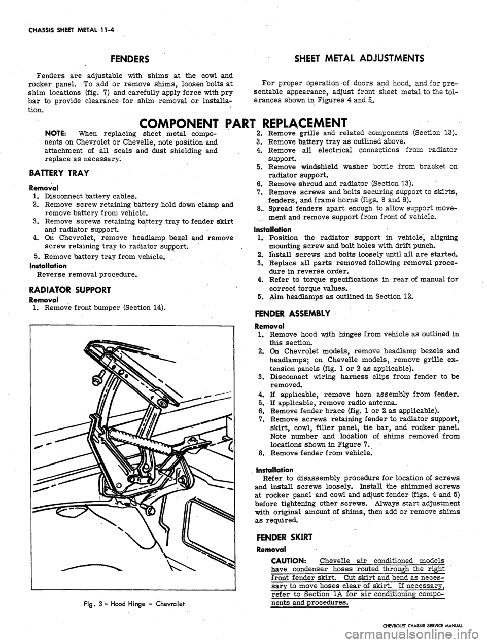
Fig.
3 - Hood Hinge - Chevrolet
2.
Remove grille and related components (Section 13).
3.
Remove battery tray as outlined above.
4.
Remove all electrical connections from radiator
support.
5.
Remove windshield washer bottle from bracket on
radiator support.
6. Remove shroud and radiator (Section 13).
7.
Remove screws and bolts securing support to skirts,
fenders, and frame horns (figs. 8 and 9).
8.. Spread fenders apart enough to allow support move-
ment and remove support from front of vehicle.
Installation
1.
Position the radiator support in vehicle", aligning
mounting screw and bolt holes with drift punch.
2.
install screws and bolts loosely until all are started.
3.
Replace all parts removed following removal proce-
dure in reverse order.
4.
Refer to torque specifications in rear of manual for
correct torque values.
•
5.
Aim headlamps as outlined in Section 12.
FENDER ASSEMBLY
Removal
1.
Remove hood with hinges from vehicle as outlined in
this section.
2.
On Chevrolet models, remove headlamp bezels and
headlamps; on Chevelle models, remove grille ex-
tension panels (fig. 1 or 2 as applicable).
3.
Disconnect wiring harness clips from fender to be
removed.
4.
If applicable, remove horn assembly from fender.
5.
If applicable, remove radio antenna.
6. Remove fender brace (fig. 1 or 2 as applicable).
7.
Remove screws retaining fender to radiator support,
skirt, cowl, filler panel, tie bar, and rocker panel.
Note number and location of shims removed from
locations shown in Figure 7.
8. Remove fender from vehicle.
Installation
Refer to disassembly procedure for location of screws
and install screws loosely. Install the shimmed screws
at rocker panel and cowl and adjust fender (figs. 4 and 5)
before tightening other screws. Always start adjustment
with original amount of shims, then add or remove shims
as required.
FENDER SKIRT
Removal
CAUTION: Chevelle air conditioned models
have condenser hoses routed through the right
front fender skirt. Cut skirt and bend as neces-
sary to move hoses clear of skirt. If necessary,
refer to Section 1A for air conditioning compo-
nents and procedures.
CHEVROLET CHASSIS SERVICE MANUAL
Page 533 of 659
ELECTRICAL-BODY AND CHASSIS 12-21
2.
Remove ash tray, retainer attaching screws and
retainer.
3.
Remove Air Conditioning distributor
duct'
retaining
screws and duct.
4.
Remove heater and/or Air Conditioning control panel
assembly retaining screws and push panel assembly
from console.
NOTE:
If interference between control panel
and radio is encountered, loosen radio retaining
nuts.
5. Remove radio control knobs, bezels and retaining
nuts.
6. Disconnect radio wiring harness and antenna lead-in.
7. Remove radio rear brace attaching screw and re-
move ra(Jio from vehicle.
8. Remove ignition switch bezel nut using Tool J-7607
and push switch rearward.
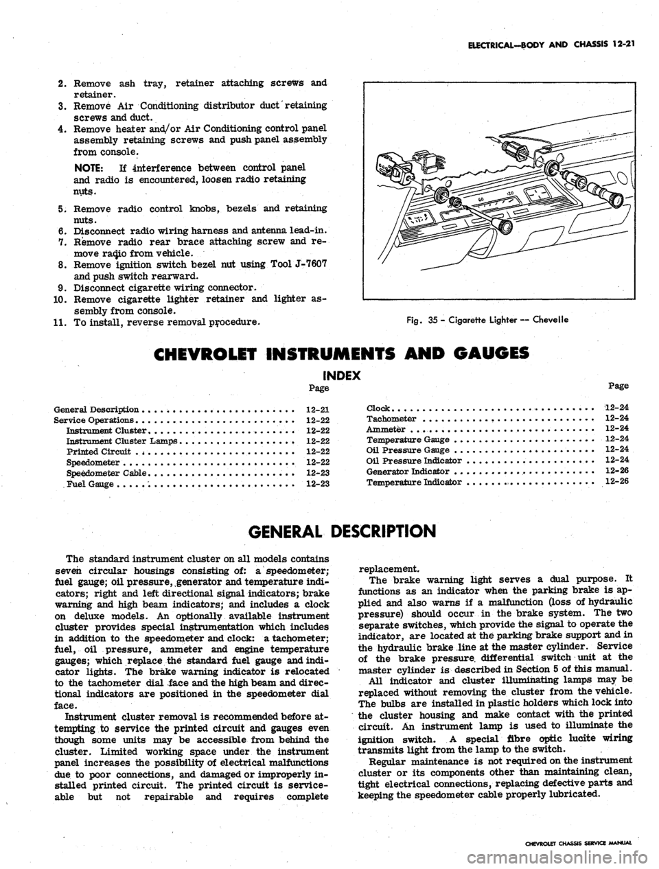
9. Disconnect cigarette wiring connector.
10.
Remove cigarette lighter retainer and lighter as-
sembly from console.
11.
To install, reverse removal procedure.
Fig.
35 - Cigarette Lighter — Chevelle
CHEVROLET INSTRUMENTS AND GAUGES
INDEX
Page
General Description 12-21
Service Operations 12-22
Instrument Cluster........................ 12-22
Instrument Cluster Lamps 12-22
Printed Circuit .
* •
12-22
Speedometer 12-22
Speedometer Cable 12-23
Fuel Gauge 12-23
Page
Clock 12-24
Tachometer 12-24
Ammeter . . 12-24
Temperature Gauge 12-24
Oil Pressure Gauge 12-24
Oil Pressure Indicator 12-24
Generator Indicator 12-26
Temperature Indicator 12-26
GENERAL DESCRIPTION
The standard instrument cluster on all models contains
seven circular housings consisting of: a speedometer;
fuel gauge; oil pressure, generator and temperature indi-
cators; right and left directional signal indicators; brake
warning and high beam indicators; and includes a clock
on deluxe models. An optionally available instrument
cluster provides special instrumentation which includes
in addition to the speedometer and clock: a tachometer;
fuel, oil pressure, ammeter and engine temperature
gauges; which replace the standard fuel gauge and indi-
cator lights. The brake warning indicator is relocated
to the tachometer dial face and the high beam and direc-
tional indicators are positioned in the speedometer dial
face.
Instrument cluster removal is recommended before at-
tempting to service the printed circuit and gauges even
though some units may be accessible from behind the
cluster. Limited working space under the instrument
panel increases the possibility of electrical malfunctions
due to poor connections, and damaged or improperly in-
stalled printed circuit. The printed circuit is service-
able but not repairable and requires complete
replacement.
The brake warning light serves a dual purpose. It
functions as an indicator when the parking brake is ap-
plied and also warns if a malfunction (loss of hydraulic
pressure) should occur in the brake system. The two
separate switches, which provide the signal to operate the
indicator, are located at the parking brake support and in
the hydraulic brake line at the master cylinder. Service
of the brake pressure, differential switch unit at the
master cylinder is described in Section 5 of this manual.
All indicator and cluster illumihating lamps may be
replaced without removing the cluster from the vehicle.
The bulbs are installed in plastic holders which lock into
the cluster housing and make contact with the printed
circuit. An instrument lamp is used to illuminate the
ignition switch. A special fibre optic lucite wiring
transmits light from the lamp to the switch.
Regular maintenance is not required on the instrument
cluster or its components other than maintaining clean,
tight electrical connections, replacing defective parts and
keeping the speedometer cable properly lubricated.
CHEVROLET CHASSIS SERVICE MANUAL
Page 538 of 659
ELECTRICAL-BODY
AND
CHASSIS
12-26
•
Low oil
pressure
• High engine temperature
• Defective wiring
or
switch
connector from sender
in block above starter
on
and
at
left front
of
distributor
on V-8
Sending Unit Replacement
1.
Disconnect wiring harness
unit terminal (located
L-6 engines
engines).
2.
Remove sender unit using Tool J-21757
or 12
point
socket, replace with
new
unit
and
check operation.
GENERATOR INDICATOR
1.
Ignition
on,
Engine
not
Running
and
Telltale Light
Off.
• Indicator bulb burned out, replace bulb.
• Open circuit
or
loose connection
in the
telltale
light circuit.
2.
telltale Light Stays
on
after Engine
is
Started.
If indicator light does
not go out at
engine idle
speed, refer
to
Charging Systems under Engine
Electrical, Section
6Y.
TEMPERATURE (COOLING SYSTEM) INDICATOR
The temperature indicator circuit consists
of two re-
motely located units, indicator gauge
and
engine sender
unit.
The
indicator gauge, located
in the
instrument
panel, consists
of a
red light which will indicate
an
over-
heated engine condition.
Engine Sender Unit Replacement
1.
Drain engine cooling system
to a
level below unit.
2.
Remove sender unit (located
in the
inlet manifold
near water pump housing
on V-8
engines and
in the
cylinder head near
an
exhaust port
oh L-6
engines)
and replace with new unit.
3.
Refill cooling system
and
check operation
of
unit.
CHEVELLE INSTRUMENTS AND GAUGES
INDEX
Page
General Description
* *
i2-26
Service Operations
12-26
Instrument Panel
12-26
Instrument Cluster.
12-26
Fuel Gauge and/or Ammeter
12-27
Clock,
i 12-27
Speedometer
12-27
Page
Speedometer Cable
.
. 12-27
Temperature Gauge
12-29
Oil Pressure Gauge
12-29
Indicator Lights.
. 12-29
Oil Pressure Indicator
12-29
Generator Indicator
. . 12-29
• Temperature Indicator
12-29
GENERAL DESCRIPTION
The Chevelle instrument cluster assembly consists
of:
a speedometer;
a
fuel gauge;
a
generator,
an
engine
tem-
perature and an
oil
pressure indicator lamp, and includes
a clock
on
deluxe models.
On
super sport models,
am-
meter, coolant temperature
and oil
pressure gauges
re-
place
the
appropriate indicator lights. Except
for the
speedometer,
all of the
indicator lamps, instruments
and
gauges
of
these clusters may
be
serviced without remov-
ing
the
instrument cluster assembly from
the
vehicle.
In addition
to the
instrument indicator lamps,
a
brake
warning lamp
is
included
in the
cluster
as
standard
equipment.
The
indicator
is
connected
to the
parking
brake
and
brake pressure differential switches
and
serves
a
dual function.
It
lights when the parking brake
is applied
and
also when
the
brake pedal
is
applied,
if a
malfunction should occur
in the
brake system
due to a
loss
of
hydraulic pressure. Servicing
of the
hydraulic
pressure differential switch
is
covered
in
Section
5 of
this manual.
Regular maintenance
is not
required on the instrument
cjLuster
or its
components other than maintaining dean
and tight electrical connections, replacing defective parts
and keeping
the
speedometer cable properly lubricated.
SERVICE OPERATIONS
INSTRUMENT PANEL ASSEMBLY
INSTRUMENT CLUSTER (Figs.
41
thru
44)
Removal
1.
Disconnect battery ground cable.
2.
Remove steering coupling bolt and disconnect steer-
ing shaft from coupling.
3.
Loosen mast jacket lower clamp.
4.
Remove
air
conditioning center distributor duct
(if
so equipped).
5. Remove radio rear support bracket screw.
6. Remove mast jacket upper support clamp and retain-
ing bolts from lower support (refer
to
Section
9,
Steering).
CAUTION: Cover mast jacket
and
parl
brake handle with
a
suitable material
to
prevc
scratching.
7.
Disconnect speedometer cable
at
rear
of
cluster
housing
and
speed warning control knob
at
panel
(if
so equipped).
8. Remove instrument panel retaining screws (nine
upper and five lower).
.
9. Working under the console remove four lower retain-
ing screws from instrument cluster housing.
10.
Pull instrument panel assembly from console and
lay
forward on mast jacket.
11.
Disconnect wiring harness, cluster lamps and wiring
CHEVROLET CHASSIS SERVICE MANUAL
Page 539 of 659
ELECTRICAL-BODY AND CHASSIS 12-27
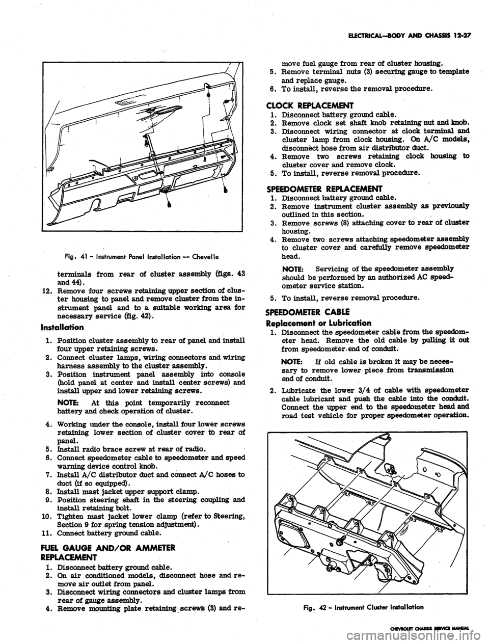
Fig.
41 - Instrument Panel Installation — Chevelle
terminals from rear of cluster assembly (figs. 43
and 44).
12.
Remove four screws retaining upper section of dus-
ter housing to panel and remove cluster from the in-
strument panel and to a suitable working area for
necessary service (fig. 42).
Installation
1.
Position cluster assembly to rear of panel and install
four upper retaining screws.
2.
Connect cluster lamps, wiring connectors and wiring
harness assembly to the cluster assembly.
3.
Position instrument panel assembly into console
(hold panel at center and install center screws) and
install upper and lower retaining screws.
NOTE:
At this point temporarily reconnect
battery and check operation of cluster.
4.
Working under the console, install four lower screws
retaining lower section of cluster cover to rear of
panel.
5. Install radio brace screw at rear of radio.
6. Connect speedometer cable to speedometer and speed
warning device control knob.
7. Install A/C distributor duct and connect A/C hoses to
duct (if so equipped).
8. Install mast jacket upper support clamp.
9. Position steering shaft in the steering coupling and
install retaining bolt.
10.
Tighten mast jacket lower clamp (refer to Steering,
Section 9 for spring tension adjustment).
11.
Connect battery ground cable.
FUEL GAUGE AND/OR AMMETER
REPLACEMENT
1.
Disconnect battery ground cable.
2.
On air conditioned models, disconnect hose and re-
move air outlet from panel.
3.
Disconnect wiring connectors and cluster lamps from
rear of gauge assembly.
4.
Remove mounting plate retaining screws (3) and re-
move fuel gauge from rear of cluster housing.
5. Remove terminal nuts (3) securing gauge to template
and replace gauge.
6. To install, reverse the removal procedure.
CLOCK REPLACEMENT
1.
Disconnect battery ground cable.
2.
Remove clock set shaft knob retaining nut and knob.
3.
Disconnect wiring connector at clock terminal and
cluster lamp from clock housing. On A/C models,
disconnect hose from air distributor duct.
4.
Remove two screws retaining clock housing to
cluster cover and remove clock.
5. To install, reverse removal procedure.
SPEEDOMETER REPLACEMENT
1.
Disconnect battery ground cable.
2.
Remove instrument cluster assembly as previously
outlined in this section.
3.
Remove screws (8) attaching cover to rear of cluster
housing.
4.
Remove two screws attaching speedometer assembly
to cluster cover and carefully remove speedometer
head.
NOTE:
Servicing of the speedometer assembly
should be performed by an authorized
AC
speed-
ometer service station.
5. To install, reverse removal procedure.
SPEEDOMETER CABLE
Replacement or Lubrication
1.
Disconnect the speedometer cable from the speedom-
eter head. Remove the old cable by pulling it out
from speedometer
, end
of conduit.
NOTE:
If old cable is broken it may be neces-
sary to remove lower piece from transmission
end of conduit.
2.
Lubricate the lower 3/4 of cable with speedometer
cable lubricant and push the cable into the conduit.
Connect the upper end to the speedometer head and
road test vehicle for proper speedometer operation.
Fig.
42 - Instrument Cluster Installation
CHEVROLET CHASSIS SEtVKE MANUAL
Page 575 of 659
ELECTRICAL-BODY AND CHASSIS 12-63
R.H. COURTESY
LP,
(67 MODELS &
16600 ONLY)
•18Y
R. H. DOOR JAMB
SW
(ALL EXCEPT 15300-400)
BK.
NEU.
LP.SW.SAF.SW.
(RJ»JD^
20 OR
20 OR
COMPT
(U*INST. PANEL COMP. LAMP
R-i3r
(ALL EXCEPT 15300-400)
14BRN
18
LBL
18 OR
14 OR
HEATER
CONTROL
LP.
RADIO CONN.
CIG.
LGT
20
P —
4
PPL
20
LG'
14 PPL—
NSOLE
CONN.
(16700-800
ONLY)
CONSOLE
CONN.
(16700-800
ONLY)
12
PPL
14 OR
12 PPL/W
20
GY/B
20 OR
14 OR
20 OR
14 OR
20 OR
20DBL
20 OR
20
GY
INSTRUMENT
CLUSTER
-ILLUM
-ILLUM
-R.H.
S
-GEN
-OILP
-ILLUM
-ILLUM
20 GY
20 GY
20DBI
20DBL/W
18
W
16BRN
-CLOCK-—:(i??T0°)
-ILLUM
^™LY
18
B
18
DBL
18
LBL
-HIGH BEAM—(11
-ILLUM
-
FUEL-GAGE —{30
-ILLUM
-ILLUM-^
-PARK BRAKE
ALARM & BRAKE
WARN. LIGHT
-ENG TEMP.—(35),
(39
-L.H.
SIG.
LAMP—(14
-ILLUM
-
TRAFFIC
HAZARD
SW.
20
LBL
20
P
16BRN
20
LG
20
PPL
14
LBL
20
T
20 OR
20 DG
20 OR
20
t
20 DG
20
Y
20
LG
20
BRN
12
PPL
PARK BRAKE
SW.
20 DBL/W
20 DG
12R
20 DG
10 OR
12
GY
20 OR
18
W
18
W
14
LBL
14T/W
14
B
SW.
67
MOD ONLY
L.H. COURT
LP.
(67 MODELS
&
16600 ONLY)
18 W-'
T/G WINDOW
SW.
(45 MOD ONLY)
DOOR JAMB
SW.
(ALL EXCEPT 15300-400)
Fig.
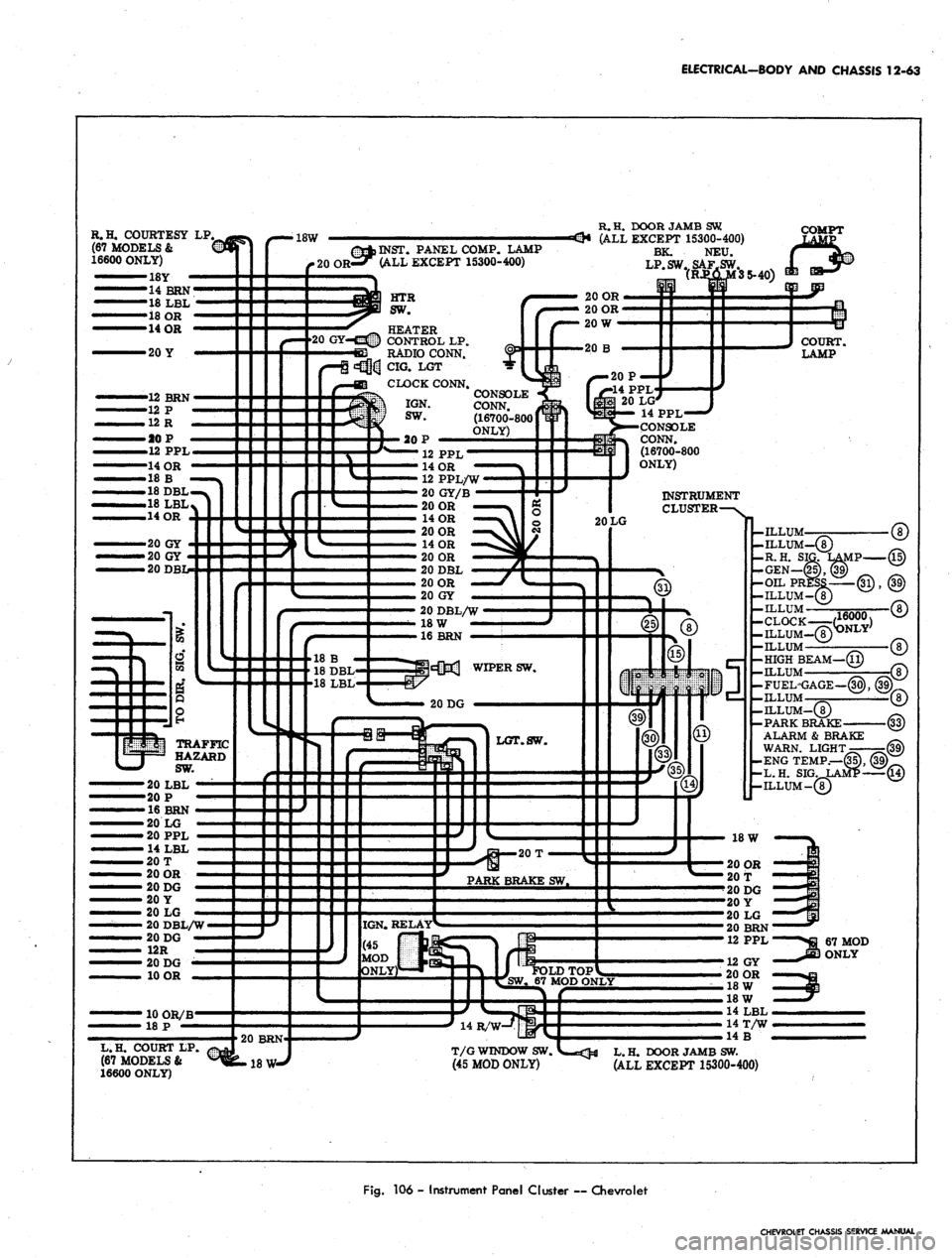
106 - Instrument Panel Cluster ~ Chevrolet
CHEVROLET CHASSIS SERVICE MANUAL
Page 580 of 659
ELECTRICAL-BODY AND CHASSIS 12-68
-7«3« R.H. DR. JAMB.SW.
C_18W-^{|>R.H. COURT
es RADIO CONN.
c5£ siHp INST. PANEL
COMPT. LAMP
ALL EXCEPT
(13100-400)
HEATER
CONTROL
HTR. CONTROL
LAMP
IGNITION SW.
LGT.
R. TURN IND.
INST.'CL. LP.
HEATER
RESISTOR
18 OR
20 Y
12 PPL/W
12 R
12 P
20 DG
14BRN
12 BRN
24 BRN/W
14
OR
20 GY
12 PPL/W
12 R
12 P
24 BRN/W
14
OR
BRK. ALARM
IND.
HI BEAM
IND.
LP.
GEN. IND. LP.
TEMP. IND. LP
INST* CL. LP.
OIL PRESS
IND.
LP.
HORN BUTTON
TO TRAFFIC
HAZARD SW.
20DBL
INST. CL. LP.
INST. CL. LP.
18 LBL
18 B
18DBL
r—20
BRN
20 OR
20
OR
20 PPL
4 LBL
20 DG
12 R
18 OR
BODY HARNESS
18 W—O-18W
^-20 BRN
20 LG
20 Y
20 DG
L.H. DR. JAMB SW.
20 LG
20 Y
20 DG
Fig.
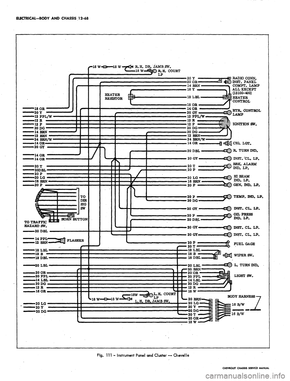
Ill - Instrument Panel and Cluster — CheveNe
CHEVROLET CHASSIS SERVICE MANUAL
Page 588 of 659
ELECTRICAL-BODY AND CHASSIS 12-76
20 OR
•431 INST. COMPT. LAMP&SW.
14 B
«3@H}U
EMM RADIO CONN.
HEATER SW.
-12 PPL
CLOCK
CLOCK LAMPS
HEATER CONT. LP.
20 GY
14LBL
14 BRN
14 Y
14 o:
14
OR
20 OR
20 B
12 R BAT.
12 P
12 P IGN.
12 PPL SOL.
12BRNAC
20 GY
GY
20 GY
14 OR
12 BRN
12 R
12 R
14 BRN-*
12 BRN—
20 DG
TRAFFIC HAZARD SW.
666SSSB
20DBL
20LBL
20 T
HORN
CONTACT
16B/W
20 LG
18 P
12 R
18 GY/DBL/B
20 B
14
OR
14 LBL
16 B
20
W
12 R
^
18
LBL
14 LBL
20 PP
18 OR
20 BRN
16
DG
IGNTTION SWITCH
GROUND
IGNITION LAMP
INST. LAMP
RADIO CAPACITOR CONN.
TEMP. GAGE
INST. LAMP
INST. LAMP
H. DIR. SIG. LAMP
INST. LAMP
CIGARETTE
SI
"MW LIGHTER & LAMP
INST. LAMP
CLUSTER GROUND
LAMP TELL-TALX LAMP
HI-BEAM LAMP
INST. LAMP
PARK ALARM LAMP
INST. LAMP
W/S WIPER
SWITCH
AMMETER
H. DIR. SIG. LAMP
INST. LAMP
FUEL GAGE
LIGHT SWITCH
-20 P
Fig.
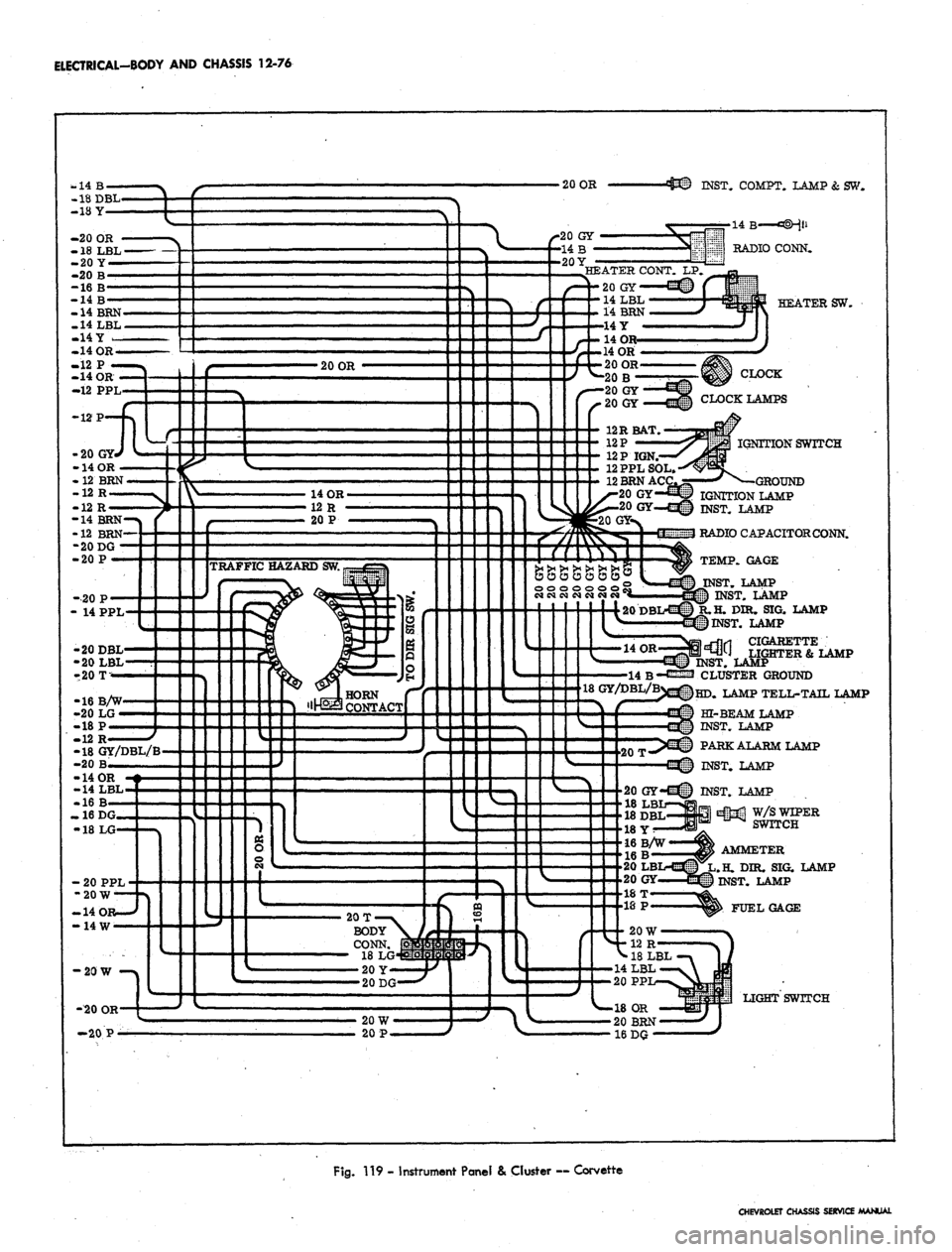
119 - Instrument Panel & Cluster ~ Corvette
CHEVROLET CHASSIS SERVICE MANUAL
Page 592 of 659
ELECTRICAL-BODY AND CHASSIS 12-80
L.H. DOOR
JAMBSW
— —20Y
20QR
«
«t5§ COMPT LP
RADIO
HEAT .
CONTROL SW
HEAT CONTROL
LIGHT
CJG LIGHTER
14OR
20GY
20GY
•ONLY WIRES
PERTINENT
TO PRODUC-
TION OR NEU-
TRAL SAFETY
HAVE BEEN
SHOWN.
20T—
20P —
20P —
18DBL
20LBL
20T
12PPL
20LBL
20 T
14 OR
16BRN
20DBL
20 W
18LBI
18DBL
20LG
20DG
20 DG
20BRN
20OR
20PPL
14LBL
14OR
48LBL
18B
18DBL
R.H. DOOR
JAMBSW
•INSTRUMENT
CLUSTER
ILLUM <8)
BRAKE ALARM (33-39)
R.H. SIGLAMP(15)
GEN WARN. LAMP (25-39)
ILLUM (8)
ILLUM (8)
FUEL GAGE (39-30)
OIL PRESS. WARN. (31-39)
L.H. SIGLAMP (14) .
ENG TEMP WARN. LP (35-39)
ILLUM (8)
HIGH BEAM LAMP
LIGHT
SW "
W/S WIPER
SW
BODY HARNESS
Fig.
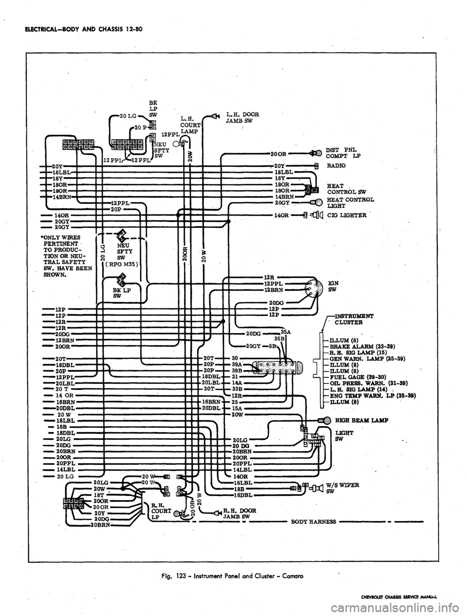
123 - Instrument Panel and Cluster - Camaro
CHEVROLET CHASSIS SERVICE MANUAL
Page 653 of 659
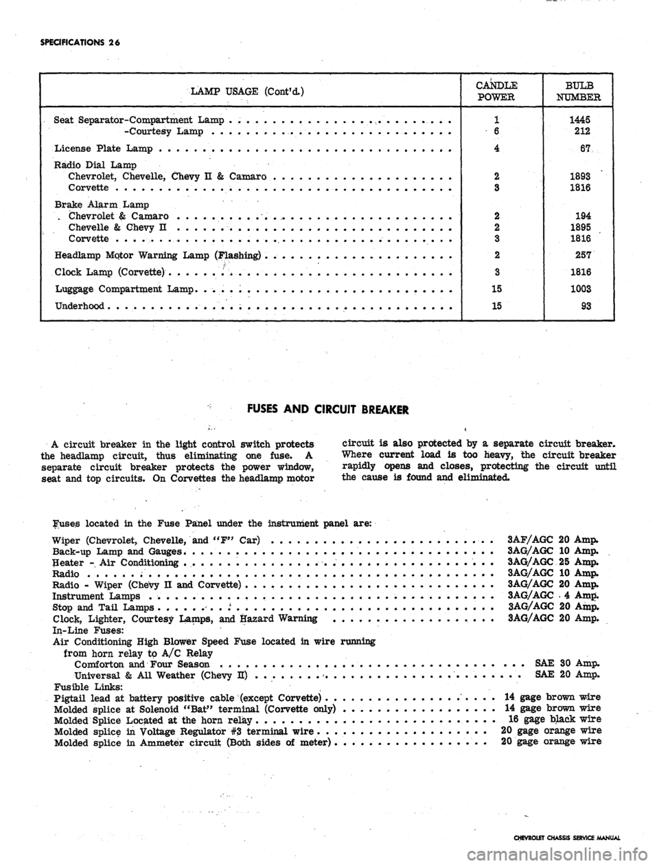
SPECIFICATIONS 26
LAMP USAGE (Cont'd.)
CANDLE
POWER
1
6
4
2
3
2
2
3
2
3
15
15
BULB
NUMBER
1445
212
67
1893
1816
194
1895
1816
257
1816
1003
93
Seat Separator-Compartment Lamp . . . . .
-Courtesy Lamp •
License Plate Lamp . .
Radio Dial Lamp
Chevrolet, Chevelle, Chevy n & Camaro
Corvette
Brake Alarm Lamp
. Chevrolet & Camaro . . .... . .
Chevelle & Chevy n . . . . .'. ;v . . . .
Corvette . . . . . . . .
Headlamp Mqtor Warning Lamp (Flashing) .
Clock Lamp (Corvette) .''> ....
Luggage Compartment Lamp. . ... . . . •
Underhood
FUSES AND CIRCUIT BREAKER
A circuit breaker in the light control switch protects
the headlamp circuit, thus eliminating one fuse. A
separate circuit breaker protects the power window,
seat and top circuits. On Corvettes the headlamp motor
circuit is also protected by a separate circuit breaker.
Where current load is too heavy, the circuit breaker
rapidly opens and closes, protecting the circuit until
the cause is found and eliminated.
louses located in the Fuse Panel under the instrument panel are:
Wiper (Chevrolet, Chevelle, and "F" Car) 3AF/AGC 20 Amp.
Back-up Lamp and Gauges. . . 3AG/AGC 10 Amp.
Heater - Air Conditioning 3AG/AGC 25 Amp.
Radio 3AG/AGC 10 Amp.
Radio - Wiper (Chevy II and Corvette) 3AG/AGC 20 Amp.
Instrument Lamps 3AG/AGC . 4 Amp.
Stop and Tail Lamps ........ t 3AG/AGC 20 Amp.
Clock, Lighter, Courtesy Lamps, and Hazard Warning 3AG/AGC 20 Amp.
In-Line Fuses:
Air Conditioning High Blower Speed Fuse located in wire running
from horn relay to A/C Relay
Comforton and Four Season SAE 30 Amp.
Universal & All Weather (Chevy H) SAE 20 Amp.
Fusible Links: ,
Pigtail lead at battery positive cable (except Corvette) 14 gage brown wire
Molded splice at Solenoid "Bat" terminal (Corvette only) 14 gage brown wire
Molded Splice Located at the horn relay 16 gage black wire
Molded splice in Voltage Regulator #3 terminal wire 20 gage orange wire
Molded splice in Ammeter circuit (Both sides of meter) 20 gage orange wire
CHEVROLET CHASSIS SERVICE MANUAL