weight CHEVROLET CAMARO 1967 1.G Chassis Owner's Manual
[x] Cancel search | Manufacturer: CHEVROLET, Model Year: 1967, Model line: CAMARO, Model: CHEVROLET CAMARO 1967 1.GPages: 659, PDF Size: 114.24 MB
Page 238 of 659
BRAKES 5-5
LEVEL CYLINDER
TILTED CYLINDER
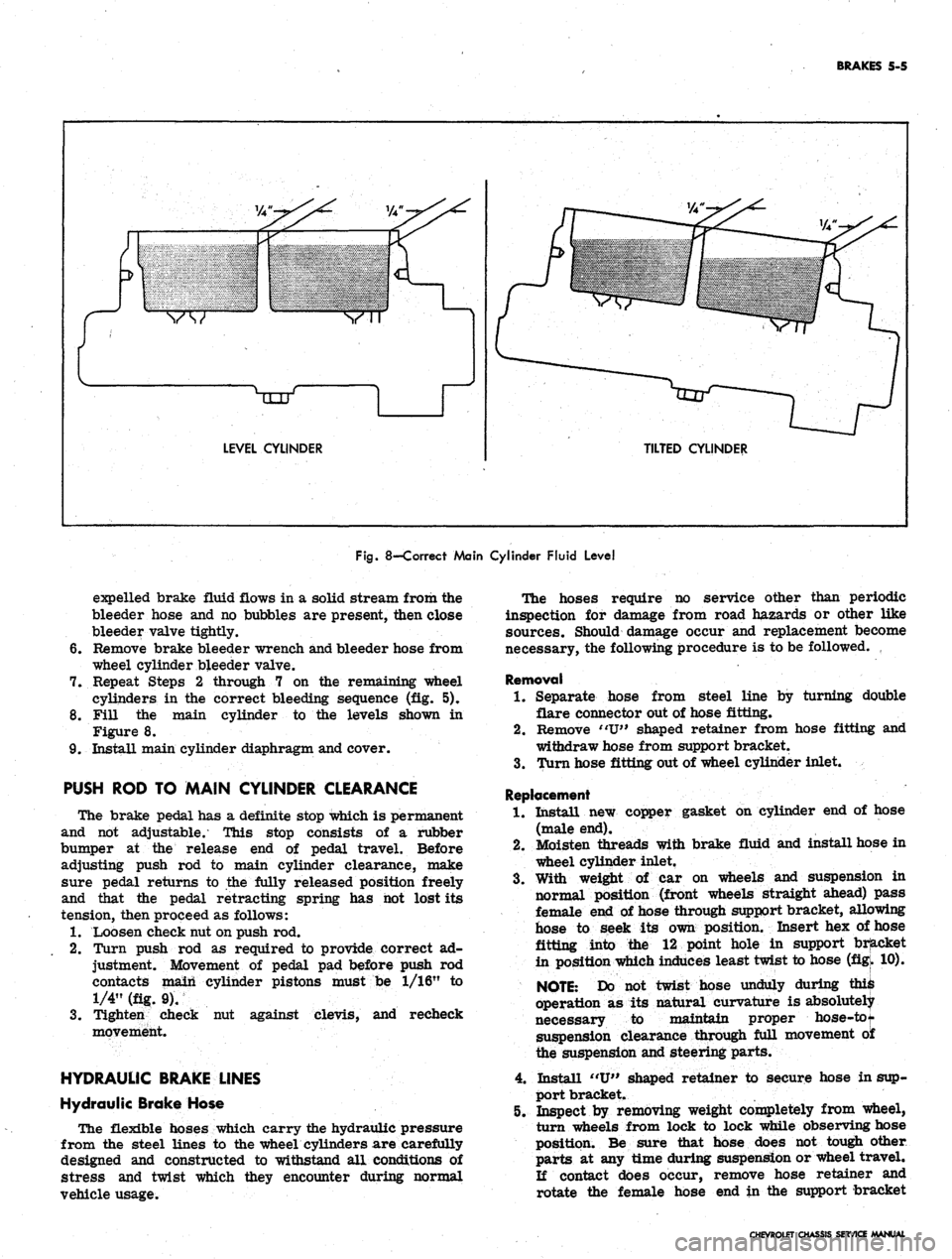
Fig.
8—Correct Main Cylinder Fluid Level
expelled brake fluid flows in a solid stream from the
bleeder hose and no bubbles are present, then close
bleeder valve tightly.
6. Remove brake bleeder wrench and bleeder hose from
wheel cylinder bleeder valve.
7. Repeat Steps 2 through 7 on the remaining wheel
cylinders in the correct bleeding sequence (fig. 5).
8. Fill the main cylinder to the levels shown in
Figure 8.
9. Install main cylinder diaphragm and cover.
PUSH ROD TO MAIN CYLINDER CLEARANCE
The brake pedal has a definite stop which is permanent
and not adjustable. This stop consists of a rubber
bumper at the release end of pedal travel. Before
adjusting push rod to main cylinder clearance, make
sure pedal returns to the fully released position freely
and that the pedal retracting spring has hot lost its
tension, then proceed as follows:
1.
Loosen check nut on push rod.
2.
Turn push rod as required to provide correct ad-
justment. Movement of pedal pad before push rod
contacts main cylinder pistons must be 1/16" to
1/4" (fig. 9).
3.
Tighten check nut against clevis, and recheck
movement.
HYDRAULIC BRAKE LINES
Hydraulic Brake Hose
The flexible hoses which carry the hydraulic pressure
from the steel lines to the wheel cylinders are carefully
designed and constructed to withstand all conditions of
stress and twist which they encounter during normal
vehicle usage.
The hoses require no service other than periodic
inspection for damage from road hazards or other like
sources. Should damage occur and replacement become
necessary, the following procedure is to be followed.
Removal
1.
Separate hose from steel line by turning double
flare connector out of hose fitting.
2.
Remove "U" shaped retainer from hose fitting and
withdraw hose from support bracket.
3.
Turn hose fitting out of wheel cylinder inlet.
Replacement
1.
Install new copper gasket on cylinder end of hose
(male end).
2.
Moisten threads with brake fluid and install hose in
wheel cylinder inlet.
3.
With weight of car on wheels and suspension in
normal position (front wheels straight ahead) pass
female end of hose through support bracket, allowing
hose to seek its own position. Insert hex of hose
fitting into the 12 point hole in support bracket
in position which induces least twist to hose (figk 10).
NOTE:
Do not twist hose unduly during ^
operation as its natural curvature is absolutely
necessary to maintain proper hose-tot
suspension clearance through full movement o£
the suspension and steering parts.
4.
Install "U" shaped retainer to secure hose in sup-
port bracket.
5. Inspect by removing weight completely from wheel,
turn wheels from lock to lock while observing hose
position. Be sure that hose does not tough other
parts at any time during suspension or wheel travel.
If contact does occur, remove hose retainer and
rotate the female hose end in the support bracket
CHEVROLET CHASSIS SERVICE MANUAL
Page 278 of 659
ENGINE 6-13
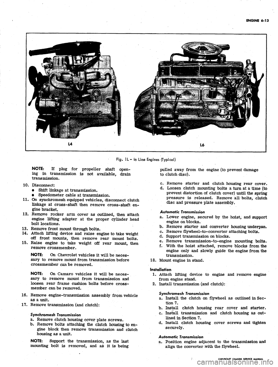
Fig.
1L- In
Line Engines (Typical)
NOTE:
If plug for propeller shaft open-
ing in transmission is not available, drain
transmission.
10.
11.
12.
Disconnect:
• Shift linkage at transmission.
• Speedometer cable at transmission.
On synchromesh equipped vehicles, disconnect clutch
linkage at cross-shaft then remove cross-shaft en-
gine bracket.
Remove rocker arm cover as outlined, then attach
engine lifting adapter at the proper cylinder head
bolt locations.
13.
Remove front mount through bolts.
14.
Attach lifting device and raise engine to take weight
off front mounts, then remove rear mount bolts.
15.
Raise engine to take weight off rear mount, then
remove crossmember.
NOTE:
On Chevrolet vehicles it will be neces-
sary to remove mount from transmission before
crossmember can be removed.
NOTE:
On Camaro vehicles it will be neces-
sary to remove mount from transmission and
loosen rear frame cushion bolts before cross-
member can be removed.
16.
Remove engine-transmission assembly from vehicle
as a unit.
17.
Remove transmission (and clutch):
Synchromesh Transmission
a. Remove clutch housing cover plate screws.
b.
Remove bolts attaching the clutch housing to en-
gine block then remove transmission and clutch
housing as a unit.
NOTE:
Support the transmission, as the last
mounting bolt is removed, and as it is being
pulled away from the engine (to prevent damage
to clutch disc).
c. Remove starter and clutch housing rear cover.
d. Loosen clutch mounting bolts a turn at a time (to
prevent distortion of clutch cover) until the spring
pressure is released. Remove all bolts, clutch
disc and pressure plate assembly.
Automatic Transmission
SL.
Lower engine, secured by the hoist, and support
engine on blocks.
b.
Remove starter and converter housing underpan.
c. Remove flywheel-to-converter attaching bolts.
d. Support transmission on blocks.
e. Remove transmission-to-engine mounting bolts.
f. With the hoist attached, remove blocks from the
engine only and slowly guide the engine from the
transmission.
18.
Mount engine in stand.
Installation
1.
Attach lifting device to engine and remove engine
from engine stand.
2.
Install transmission (and clutch):
Synchromesh Transmission
a. Install the clutch on flywheel as outlined in Sec-
tion 7.
b.
Install clutch housing rear cover and starter.
c. Install transmission and clutch housing as out-
lined in Section 7.
d. Install clutch housing cover screws and tighten
securely.
Automatic Transmission
a. Position engine adjacent to the transmission and
align the converter with the flywheel.
CHEVROLET CHASSIS SERVICE MANUAL
Page 282 of 659
ENGINE 6-17
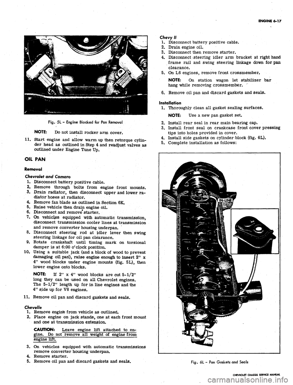
Fig.
5L
-
Engine Blocked for Pan Removal
NOTE: Do not install rocker arm cover.
11.
Start engine and allow warm up then retorque cylin-
der head
as
outlined in Step 4 and readjust valves as
outlined under Engine Tune Up.
OIL PAN
Removal
Chevrolet
and Camaro
1.
Disconnect battery positive cable.
2.
Remove through bolts from engine front mounts.
3.
Drain radiator, then disconnect upper and lower ra-
diator hoses at radiator.
4.
Remove fan blade as outlined in Section 6K.
5.
Raise vehicle then drain engine oil.
6. Disconnect and remove* starter.
7.
On
vehicles equipped with automatic transmission,
disconnect transmission cooler lines at transmission
and remove converter housing underpan.
8. Disconnect steering
rod at
idler lever then swing
steering linkage for oil pan clearance.
9. Rotate crankshaft until timing mark
on
torsional
damper is at 6:00 o'clock position.
10.
Using
a
suitable jack (and a block of wood to prevent
damaging oil pan), raise engine enough to insert 2"
x
4"
wood blocks under engine mounts (fig. 5L), then
lower engine onto blocks.
NOTE:
If
2"
x
4" wood blocks are cut 5-1/2"
long they can be used on all Chevrolet engines.
The 5-1/2" length up for in line engines and the
4"
side up for V8 engines.
11.
Remove oil pan and discard gaskets and seals.
Cfievel/e
1.
Remove enginfe from vehicle as outlined.
2.
Place engine on jack stands, one at each front mount
and one at transmission extension.
CAUTION: Leave engine lift attached
to
en-
gine.
Do not remove all weight
of
engine from
engine lift.
3.
On
vehicles equipped with automatic transmissions
remove converter housing underpan.
4.
Remove starter.
5.
Remove oil pan and discard gaskets and seals.
Chevy//
1.
Disconnect battery positive cable.
2.
Drain engine oil.
3.
Disconnect then remove starter.
4.
Disconnect-steering idler arm bracket at right hand
frame rail and swing steering linkage down for pan
clearance.
5.
On L6 engines, remove front crossmember.
NOTE:
On
station wagon
let
stabilizer
bar
hang while removing crossmember.
"
6. Remove oil pan and discard gaskets and seals.
Installation
1.
Thoroughly clean all gasket sealing surfaces.
NOTE: Use
a
new pan gasket set.
2.
Install rear seal in rear main bearing cap.
3.
Install front Seal on crankcase front cover pressing
tips into holes provided in cover.
4.
Install side gaskets on cylinder block (fig. 6L).
5.
Complete installation as follows:
Life
1
i
If ^
jfp^;.^3p
>\~^^ \s3^^r' -'••'•'-^^Hll
|^=-5p|:*iil^
mm
Fig.
6L
-
Pan Gaskets and Seals
CHEVROLET CHASSIS SERVICE MANUAL
Page 284 of 659
ENGINE 6-19
OIL SEAL (REAR MAIN)
Replacement
The rear main bearing oil seal can be replaced (both
halves) without removal of the crankshaft.
NOTE:
Always replace the upper and lower
seal as a unit. Install with the lip facing toward
the front of the engine.
1.
With the oil pan removed, remove the rear main
bearing cap.
2.
Remove oil seal from the groove by lifting the end
tab (fig. 7L) then clean seal groove.
3.
Lubricate the lip and O.D. of a new seal with engine
oil. Keep oil off the parting line surface. Insert
seal in cap and roll it into place with finger and
thumb,
using light pressure so beads on seal O.D.
are not cut by seal groove at cap parting line. Be
sure tabs on seal are properly located in cross
grooves.
4.
To remove the upper half of the seal, use a small
hammer to tap a brass pin punch on one end of seal
until it protrudes far enough to be removed with
pliers (fig. 8L).
NOTE:
Always clean crankshaft surface re-
moving all foreign deposits before installing a
new seal. Also clean seal groove.
5. Lubricate the lip and O.D. of a new seal with engine
oil. Keep oil off the parting line surface. Gradually
push with a hammer handle, while turning crank-
shaft, until seal is rolled into place. (Similar to in-
stalling a main bearing.) Be careful that seal bead
on O.D. is not cut. Compress seal towards crank-
shaft as much as possible.
6. Install the rear main bearing cap (with new seal) and
torque to specifications. Be sure cross seal tabs
are in place and properly seated.
CRANKSHAFT PULLEY AND HUB
(Chevy II with L4 Engine)
Removal
1.
Drain radiator and disconnect upper and lower radi-
ator hoses at radiator.
2.
Remove radiator core as outlined in Section 13.
3.
Remove fan belt. Remove crankshaft pulley from
pulley hub.
4.
Install puller Tool J-6978 to pulley hub with two
3/8"
x 2" and one 5/16" x 2" bolts and remove hub
then remove puller tool.
Installation
1.
Coat oil seal contact area on hub with engine oil
position hub over crankshaft and key and start hub
into position with a mallet. Using Tool J-5590 drive
onto crankshaft until it bottoms against crankshaft
gear.
NOTE:
Crankshaft extends slightly through hub
and a tool is necessary to drive hub completely
into bottomed position.
2.
Install pulley onto hub.
NOTE:
There are two 3/8" holes and one
5/16" hole that must be matched on hub in order
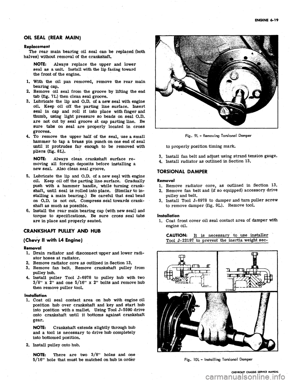
Fig.
9L - Removing Torsional Damper
to properly position timing mark.
3.
Install fan belt and adjust using strand tension gauge.
4.
Install radiator as outlined in Section 13.
TORSIONAL DAMPER
Removal
1.
Remove radiator core, as outlined in Section 13.
2.
Remove fan belt and (if so equipped) accessory drive
pulley and belt.
3.
Install Tool J-6978 to damper and turn puller screw
to remove damper (fig. 9L). Remove tool.
Installation
1.
Coat front cover oil seal contact area of damper with
engine oil.
CAUTION: It is necessary to use installer
Tool J-22197 to prevent the inertia weight sec-
Fig.
10L - Installing Torsional Damper
CHEVROLET CHASSIS SERVICE MANUAL
Page 285 of 659
ENGINE 6-20
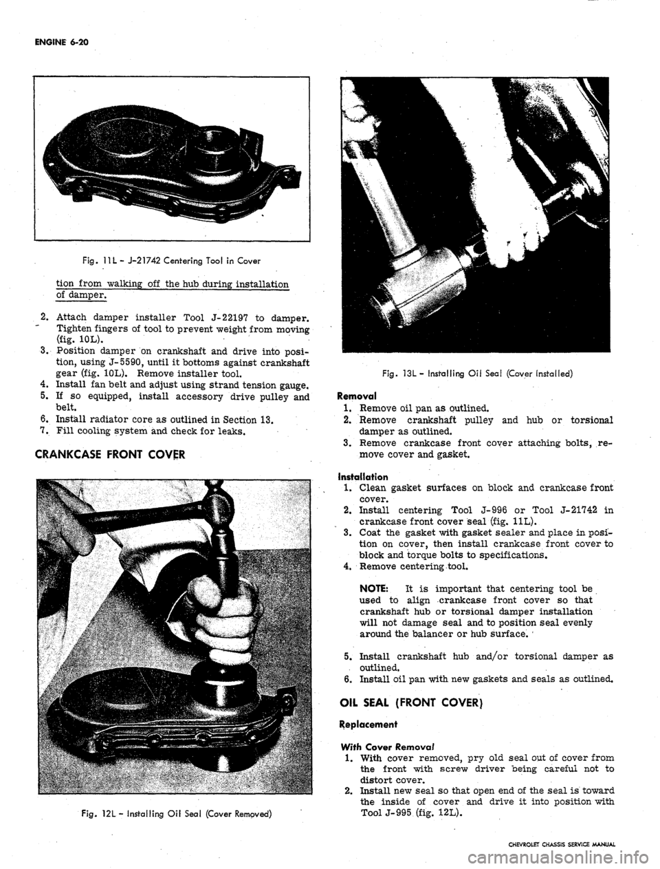
Fig.
11 L
- J-21742 Centering Tool in Cover
tion from walking off the hub during installation
of damper.
2.
3.
Attach damper installer Tool J-22197 to damper.
Tighten fingers of tool to prevent weight from moving
(fig. 10L).
Position damper on crankshaft and drive into posi-
tion, using J-5590, until it bottoms against crankshaft
gear (fig. 10L). Remove installer tool.
4.
Install fan belt and adjust using strand tension gauge.
5.
If so equipped, install accessory drive pulley and
belt.
6. Install radiator core as outlined in Section 13.
7.
Fill cooling system and check for leaks.
CRANKCASE FRONT COVER
Fig.
121
- Installing Oil Seal (Cover Removed)
Fig. 13L- Installing Oil Seal (Cover installed)
Removal
1.
Remove oil pan as outlined.
2.
Remove crankshaft pulley and hub or torsional
damper as outlined.
3.
Remove crankcase front coyer attaching bolts, re-
move cover and gasket.
Installation
1.
Clean gasket surfaces on block and crankcase front
cover.
2.
Install centering Tool J-996 or Tool J-21742 in
crankcase front cover seal (fig. 11L).
3.
Coat the gasket with gasket sealer and place in posi-
tion on cover, then install crankcase front cover to
block and torque bolts to specifications.
4.
Remove centering tool.
NOTE: It is important that centering tool be
used to align crankcase front cover so that
crankshaft hub or torsional damper installation
will not damage seal and to position seal evenly
around the balancer or hub surface.
5.
Install crankshaft hub and/or torsional damper as
outlined.
6. Install oil pan with new gaskets and seals as outlined.
OIL SEAL (FRONT COVER)
Replacement
With Cover Removal
1.
With cover removed, pry old seal out of cover from
the front with screw driver being careful not to
distort cover.
2.
Install new seal so that open end of the seal is toward
the inside of cover and drive it into position with
ToolJ-995 (fig. 12L).
CHEVROLET CHASSIS SERVICE MANUAL
Page 288 of 659
ENGINE 6-23
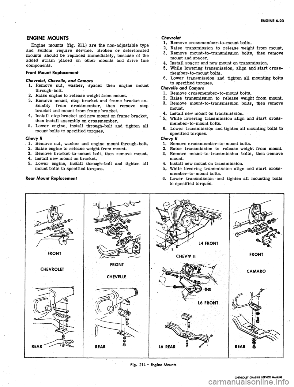
ENGINE MOUNTS
Engine mounts (fig. 21L) are the non-adjustable type
and seldom require service. Broken or deteriorated
mounts should be replaced immediately, because of the
added strain placed on other mounts and drive line
components.
Front Mount Replacement
Chevrolet,
Chevelle, and Comoro
1.
Remove nut, washer, spacer then engine mount
through-bolt.
2.
Raise engine to release weight from mount.
3.
Remove mount, stop bracket and frame bracket as-
sembly from crossmember, then remove stop
bracket and mount from frame bracket.
4.
Install stop bracket and new mount on frame bracket,
then install assembly on crossmember.
5.
Lower engine, install through-bolt and tighten all
mount bolts to specified torques.
Chevy II
, 1. Remove nut, washer and engine mount through-bolt.
2.
Raise engine to release weight from mount.
3.
Remove bracket-to-mount bolt, then remove mount.
4.
Install new mount on bracket.
5.
Lower engine, install through-bolt and tighten all
mount bolts to specified torques.
Rear Mount Replacement
Chevrolet
1.
Remove crossmember-to-mount bolts.
2.
Raise transmission to release weight from mount.
3.
Remove mount-to-trans mission bolts, then remove
mount and spacer.
4.
Install spacer and new mount on transmission.
5.
While lowering transmission, align and start cross-
member-to-mount bolts.
6. tower transmission and tighten all mounting bolts
to specified torques.
Chevelle and Camaro
1.
Remove crossmember-to-mount bolts.
2.
Raise transmission to release weight from mount.
3.
Remove mount-to-transmission bolts, then remove
mount.
4.
Install new mount on transmission.
5.
While lowering transmission align and start cross-
member-to-mount bolts.
6. Lower transmission and tighten all mounting bolts to
specified torques.
Chevy II
1.
Remove crossmember-to-mount bolts.
2.
Raise transmission to release weight from mount.
3.
Remove mount-to-transmission bolts, then remove
mount.
4.
Install new mount on transmission.
5.
While lowering transmission align and start cross-
member-to-mount bolts.
6. Lower transmission and tighten all mounting bolts
to specified torques.
FRONT
CHEVROLET
REAR
REAR
L4 FRONT
CHEVY II
L6 FRONT
L6 REAR
FRONT
CAMARO
REAR
Fig.
21L- Engine Mounts
CHEVROLET CHASSIS SERVICE MANUAL
Page 290 of 659
ENGINE 6-25
refer to Section 6 of the Chassis Overhaul Manual.
Because of the interchangeability and similarity of
many engines, engine sub-assemblies and engine parts,
regardless of which passenger vehicle they are used in,
typical illustrations and procedures are used except
where specific illustrations or procedures are necessary
to clarify the operation. Although illustrations showing
bench operations are used, most single operations, when
not part of a general overhaul, should be performed (if
practical) with the engine in the vehicle.
COMPONENT REPLACEMENT AND ADJUSTMENT
ENGINE ASSEMBLY
Removal
• .1. Drain cooling system and engine oil.
2.
Remove air cleaner and disconnect battery cables at
battery.
3.
Remove hood as outlined in Section 11.
4.
Remove radiator and shroud as outlined in Sec-
tion 13.
5. Remove fan blade and pulley as outlined in Sec-
tion 6K.
6. Disconnect wires at:
• Starter solenoid
• Delcotron
• Temperature switch
• Oil pressure switch
• Coil
7. Disconnect:
• Accelerator linkage at pedal lever.
• Exhaust pipes at manifold flanges.
• Vacuum line to power brake unit at manifold (if
so equipped),
• Power steering pump lines at pump end (if so
equipped).
• Fuel line (from tank) at fuel pump.
• Engine cooler lines (if so equipped).
• Oil pressure gauge line (if so equipped).
8. Raise vehicle and place on jack stands.
9. Remove propeller shaft.
NOTE:
If plug for propeller shaft opening
in transmission is not available, drain
transmission.
10.
Disconnect:
• Shift linkage at transmission.
• Speedometer cable at transmission.
• Transmission cooler lines (if so equipped).
11.
On synchromesh equipped vehicles, disconnect clutch
linkage at cross-shaft then remove cross-shaft en-
gine bracket.
12.
Remove rocker arm covers as outlined, then attach
engine lifting adapter at the proper cylinder head bolt
locations.
13.
Remove front mount bolts.
14.
Attach lifting device and raise engine to take weight
off front mounts, then remove rear mount bolts.
15.
Raise engine to take weight off rear mount, then re-
move crossmember.
NOTE:
On Chevrolets it will be necessary to
remove mount from transmission before cross-
member can be removed.
16.
Remove engine-transmission assembly from vehicle
as a unit.
17.
Remove transmission (and clutch):
Synchromesh Transmission
a. Remove clutch housing cover plate screws.
b.
Remove bolts attaching the clutch housing to en-
gine block then remove transmission and clutch
housing as a unit.
NOTE:
Support the transmission as the last
mounting bolt is removed, and as it is being
pulled away from the engine (to prevent damage
to clutch disc).
c. Remove starter and clutch housing rear cover
plate.
d. Loosen clutch mounting bolts a turn at a time (to
prevent distortion of clutch cover) until the spring
pressure is released. Remove all bolts, clutch
disc and pressure plate assembly.
Automatic
Transmission
a. Lower engine, secured by the hoist, and support
engine on blocks.
b.
Remove starter and converter housing underpan.
c. Remove flywheel-to-converter attaching bolts.
d. Support transmission on blocks.
e. Remove transmission-to-engine mounting bolts.
f. With the hoist attached, remove blocks from the
engine only and slowly guide the engine from the
transmission.
18.
Mount engine in stand.
Installation
1.
Attach lifting device to engine and remove engine
from engine stand.
2.
Install transmission (and clutch):
Synchromesh Transmission
a. Install the clutch on flywheel as outlined in Sec-
tion 7.
b.
Install clutch housing rear cover and starter.
c. Install transmission and clutch housing as out-
lined in Section 7.
d. Install clutch housing cover screws and tighten
securely.
Automatic
Transmissions
a. Position engine adjacent to the transmission and
align the converter with the flywheel.
b.
Bolt transmission to engine, then raise engine and
transmission assembly and install flywheel to
converter attaching bolts.
c. Install converter housing underpan and starter.
3.
Tilt and lower engine and transmission assembly into
the chassis as a unit, guiding engine to align front
mounts with frame supports.
4.
Install front mount bolts and torque to specifications.
5. Raise engine enough to install rear crossmember,
then install crossmember, install rear mount, lower
engine and torque rear mount to specifications.
CHEVROLET CHASSIS SERVICE MANUAL
Page 295 of 659
ENGINE 6-30
c". Install the valve locks and release the compres-
sor tool making sure the locks seat properly in
the upper groove of the valve stem.
NOTE: Grease may be used to hold the locks
in place while releasing the compressor tool.
396 and 427
cu.
in.
Engines
a. Install new valve stem oil seal (coated with oil)
in position over valve guide.
b.
Set the valve spring and damper and valve cap in
place.
c. Compress the spring with Tool J-5892 and install
the valve locks, then release the compressor tool,
making sure the locks seat properly in the groove
of the valve stem.
NOTE: Grease may be used to hold the locks
in place while releasing the compressor tool.
7.
Install spark ,plug, using a new gasket, and torque to
specifications. -
8. Install and adjust valve mechanism as outlined.
CYLINDER HEAD ASSEMBLY
Removal
1.
Remove intake manifold as outlined.
2.
Remove exhaust manifolds as outlined.
3.
Remove valve mechanism as outlined.
4.
Drain cooling system (block).
5.
Remove cylinder head bolts, cylinder head and gas-
ket. Place cylinder head on two blocks of wood to
prevent damage.
Installation
CAUTION: The gasket surfaces on both the
head and the block must be clean of any foreign
ttter and free of nicks or heavy scratches.
Under bolt threads in the block and threads on
Pie cylinder head bolt must be cleaned. (Dirt
will affect bolt torqueT)
1.
On engines using a STEEL gasket, coat both sides of
a new gasket with a good sealer, spread the sealer
thin and even. One method of applying the sealer that
will assure the proper- coat is with the use of a paint
roller. Too much sealer may hold the beads of the
gasket away from the head or block.
CAUTION: Use no sealer on engines using a
composition STEEL ASBESTOS gasket.
2.
Place the gasket in position over the dowel pins with
the bead up.
3.
Carefully guide cylinder head into place over dowel
pins and gasket.
4.
Coat threads of cylinder head bolts with sealing
compound and install finger tight.
5.
Tighten cylinder head bolts a little at a time in the
sequence shown on the torque sequence chart until
the specified torque is reached.
6. Install the exhaust manifold as outlined.
7.
Install the intake manifold as outlined.
8. Install and adjust the valve mechanism as outlined.
OIL
PAN
Removal
Chevrolet
and Camaro
1.
Disconnect battery positive cable.
2.
Disconnect distributor cap from distributor (to pr-e-
vent breaking distributor cap when engine is raised).
3.
Drain radiator, then disconnect lower radiator hose
at water pump and remove oil dip stick and tube
(where necessary). '
4.
Remove fan blade.
5.
Raise vehicle then drain engine oil;
6. Remove through bolts from engine front mounts.
Disconnect and remove starter.
7.
On vehicles equipped with automatic transmissions,
remove converter housing underpan.
8. Disconnect steering rod at idler lever then swing
steering linkage 4pwn for oil pan clearance.
9. Rotate crankshaft untii timing mark on torsional
damper is at 6:00 o'clock position.
10.
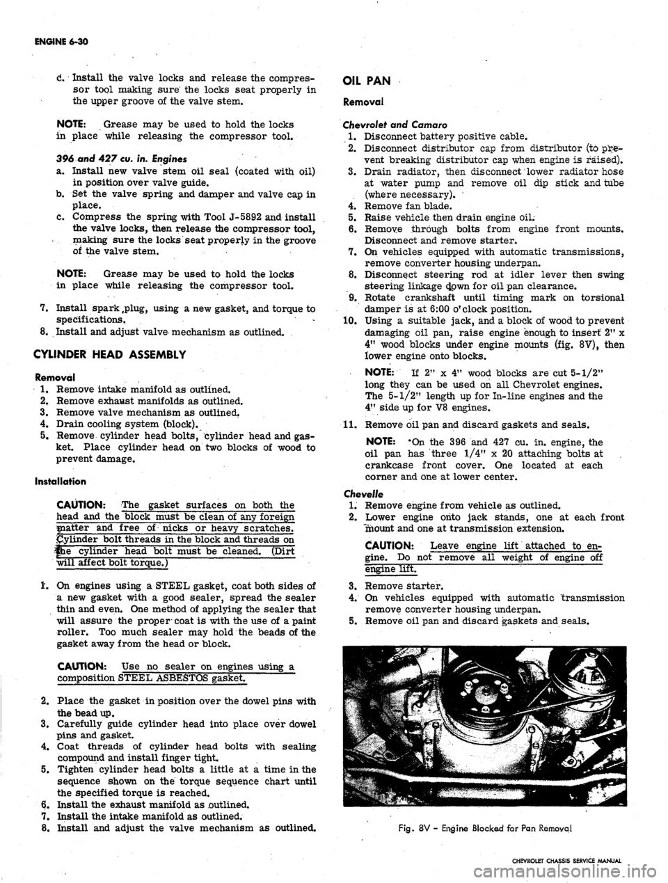
Using a suitable jack, and a block of wood to prevent
damaging oil pan, raise engine "enough to insert 2" x
4"
wood blocks under engine mounts (fig. 8V), then
lower engine onto blocks.
NOTE: If 2" x 4" wood blocks are cut 5-1/2"
long they can be used on all Chevrolet engines.
The 5-1/2" length up for In-line engines and the
4"
side up for V8 engines.
11.
Remove oil pan and discard gaskets and seals.
NOTE: -On the 396 and 427 cu. in. engine, the
oil pan has three 1/4" x 20 attaching bolts at ,
crankcase front cover. One located at each
corner and one at lower center.
Chevelle
1.
Remove engine from vehicle as outlined.
2.
Lower engine onto jack stands, one at each front
Tnaount and one at transmission extension.
CAUTION: Leave engine lift attached to en-
gine.
Do not remove all weight of engine off
engine lifET
3.
Remove starter.
4.
On vehicles equipped with automatic transmission
remove converter housing underpan.
5.
Remove oil pan and discard gaskets and seals.
Fig.
8V - Engine Blocked for Pan Removal
CHEVROLET CHASSIS SERVICE MANUAL
Page 298 of 659
ENGINE 6-33
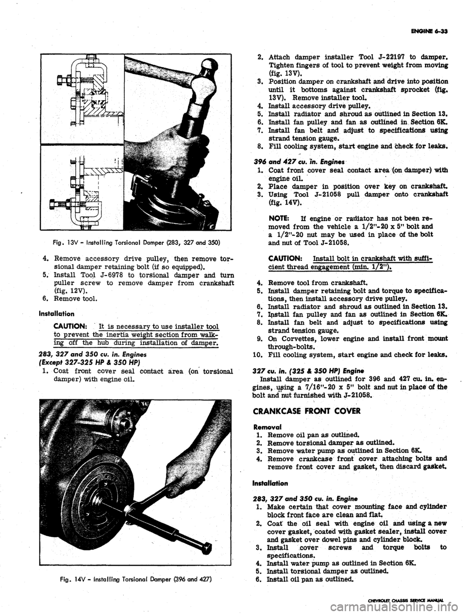
Fig.
13V - Installing TorsionaI Damper (283, 327 and 350)
4.
Remove accessory drive pulley, then remove tor-
sional damper retaining bolt (if so equipped).
5. Install Tool J-6978 to torsional damper and turn
puller screw to remove damper from crankshaft
(fig. 12V).
6. Remove tool.
Installation
CAUTION: It is necessary to use installer tool
to prevent the inertia weight section from walk-
ing off the hub during installation of damper.
283, 327 and 350 cu. in. Engines
(Except 327-325 HP & 350 HP)
1.
Coat front cover seal contact area (on torsional
damper) with engine oil.
Fig.
14V - Installing Torsional Damper (396 and 427)
2.
Attach damper installer Tool J-22197 to damper.
Tighten fingers of tool to prevent weight from moving
(fig. 13V).
3.
Position damper on crankshaft and drive into position
until it bottoms against crankshaft sprocket (fig.
13V).
Remove installer tool.
4.
Install accessory drive pulley.
5. Install radiator and shroud as outlined in Section 13.
6. Install fan pulley and fan as outlined in Section 6K.
7. Install fan belt and adjust to specifications using
strand tension gauge.
8. Fill cooling system, start engine and check for leaks.
396 and 427
cu.
in.
Engines
1.
Coat front cover seal contact area (on damper) with
engine oil.
2.
Place damper in position over key on crankshaft.
3.
Using Tool J-21058 pull damper onto crankshaft
(fig. 14V).
NOTE:
If engine or radiator has not been re-
moved from the vehicle a 1/2"- 20 x 5" bolt and
a
1/2"-20
nut may be used in place of the bolt
and nut of Tool J-21058.
CAUTION: Install bolt in crankshaft with suffi-
cient thread engagement (min. 1/2").
4.
Remove tool from crankshaft.
5. Install damper retaining bolt and torque to specifica-
tions,
then install accessory drive pulley.
6. Install radiator and shroud as outlined in Section 13.
7. Install fan pulley and fan as outlined in Section 6K.
8. Install fan belt and adjust to specifications using
strand tension gauge.
9. On Corvettes, lower engine and install front mount
through-bolts.
10.
Fill cooling system, start engine and check for leaks.
327
cu.
in. (325 & 350 HP)
Engine
Install damper as outlined for 396 and 427 cu. in. en-
gines,
using a 7/16"-20 x 5" bolt and nut in place of the
bolt and nut furnished with J-21058.
CRANKCASE FRONT COVER
Removal
1.
Remove oil pan as outlined.
2.
Remove torsional damper as outlined.
3.
Remove water pump as outlined in Section 6K.
4.
Remove crankcase front cover attaching bolts and
remove front cover and gasket, then discard gasket
Installation
283, 327 and 350 cu. in.
Engine
1.
Make certain that cover mounting face and cylinder
block front face are clean and flat.
2.
Coat the oil seal with engine oil and using a new
cover gasket, coated with gasket sealer, install cover
and gasket over dowel pins and cylinder block.
3.
Install cover screws and torque bolts to
specifications.
4.
Install water pump as outlined in Section 6K.
5. Install torsional damper as outlined.
6. Install oil pan as outlined.
CHEVROLET CHASSIS SOVKZ MANUAL
Page 302 of 659
ENGINE 6-37
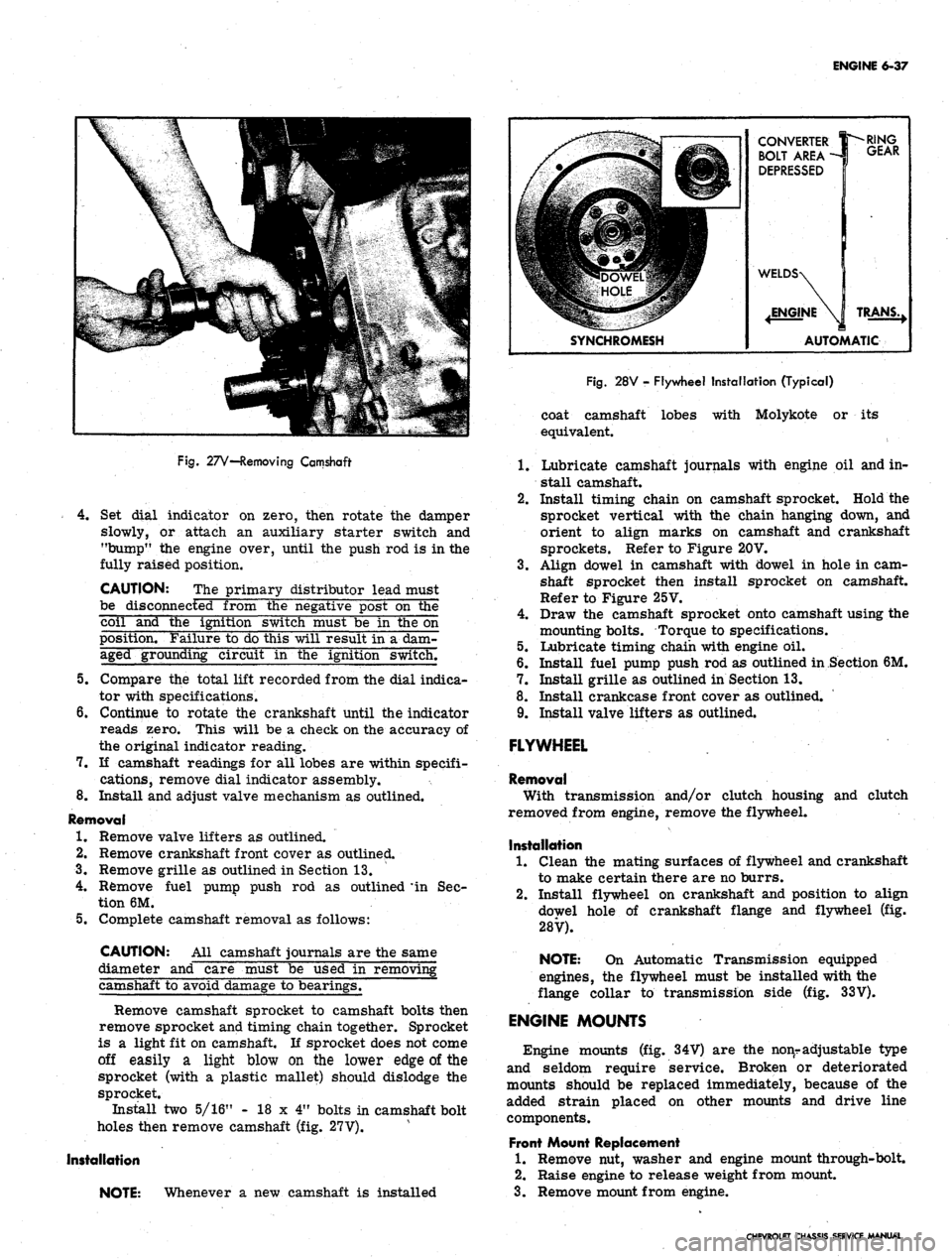
Fig.
27V—Removing Camshaft
4.
Set dial indicator on zero, then rotate the damper
slowly, or attach an auxiliary starter switch and
"bump" the engine over, until the push rod is in the
fully raised position.
CAUTION: The primary distributor lead must
be disconnected from the negative post on the
coil and the ignition switch must be in the on
position. Failure to do this will result in a dam-
aged grounding circuit in the ignition switch.
5.
Compare the total lift recorded from the dial indica-
tor with specifications.
6. Continue to rotate the crankshaft until the indicator
reads zero. This will be a check on the accuracy of
the original indicator reading.
7.
If camshaft readings for all lobes are within specifi-
cations, remove dial indicator assembly.
8. Install and adjust valve mechanism as outlined.
Removal
1.
Remove valve lifters as outlined.
2.
Remove crankshaft front cover as outlined.
3.
Remove grille as outlined in Section 13.
4.
Remove fuel pump push rod as outlined * in Sec-
tion 6M.
5.
Complete camshaft removal as follows:
CAUTION: All camshaft journals are the same
diameter and care must be used in removing
camshaft to avoid damage to bearings.
Remove camshaft sprocket to camshaft bolts then
remove sprocket and timing chain together. Sprocket
is a light fit on camshaft. If sprocket does not come
off easily a light blow on the lower edge of the
sprocket (with a plastic mallet) should dislodge the
sprocket.
Install two 5/16" - 18 x 4" bolts in camshaft bolt
holes then remove camshaft (fig. 27V).
Installation
NOTE: Whenever a new camshaft is installed
CONVERTER
BOLT AREA -
DEPRESSED
SYNCHROMESH
RING
GEAR
TRANS.,
AUTOMATIC
Fig.
28V - Flywheel Installation (Typical)
coat camshaft lobes with Molykote or its
equivalent.
1.
Lubricate camshaft journals with engine oil and in-
stall camshaft.
2.
Install timing chain on camshaft sprocket. Hold the
sprocket vertical with the chain hanging down, and
orient to align marks on camshaft and crankshaft
sprockets. Refer to Figure 20V.
3.
Align dowel in camshaft with dowel in hole in cam-
shaft sprocket then install sprocket on camshaft.
Refer to Figure 25V.
4.
Draw the camshaft sprocket onto camshaft using the
mounting bolts. Torque to specifications.
5.
Lubricate timing chain with engine oil.
6. Install fuel pump push rod as outlined in Section 6M.
7.
Install grille as outlined in Section 13.
8. Install crankcase front cover as outlined.
9. Install valve lifters as outlined.
FLYWHEEL
Removal
With transmission and/or clutch housing and clutch
removed from engine, remove the flywheel.
Installation
1.
Clean the mating surfaces of flywheel and crankshaft
to make certain there are no burrs.
2.
Install flywheel on crankshaft and position to align
dowel hole of crankshaft flange and flywheel (fig.
28V).
NOTE: On Automatic Transmission equipped
engines, the flywheel must be installed with the
flange collar to transmission side (fig. 33V).
ENGINE MOUNTS
Engine mounts (fig. 34V) are the nonr adjustable type
and seldom require service. Broken or deteriorated
mounts should be replaced immediately, because of the
added strain placed on other mounts and drive line
components.
Front Mount Replacement
1.
Remove nut, washer and engine mount through-bolt.
2.
Raise engine to release weight from mount.
3.
Remove mount from engine.
CHEVROLET CHASSIS SERVICE MANUAL