clock CHEVROLET CAMARO 1967 1.G Chassis Service Manual
[x] Cancel search | Manufacturer: CHEVROLET, Model Year: 1967, Model line: CAMARO, Model: CHEVROLET CAMARO 1967 1.GPages: 659, PDF Size: 114.24 MB
Page 458 of 659
STEERING 9-18
I.D. of the lockplate with the slots in the top of the
jacket.
16.
Lock upper end assembly into position by pushing 18.
down on the cover assembly and rotating assembly
fully clockwise. Tangs on lock plate must engage
slots in jacket. 19.
17.
Tighten three turn signal switch mounting screws in
a gradual criss-cross sequence to avoid cocking the
lockplate.
Screw tolerance ring kit sections together leaving
enough inner edge exposed for later adjustment as
shown in Figure 35.
Slide wave washer and thrust washer over steering
shaft against upper bearing housing.
17 15 13 11 9 7 5 3
34 V33 29 27 26
36 35 32 3130 28
46 45 44 -43 42
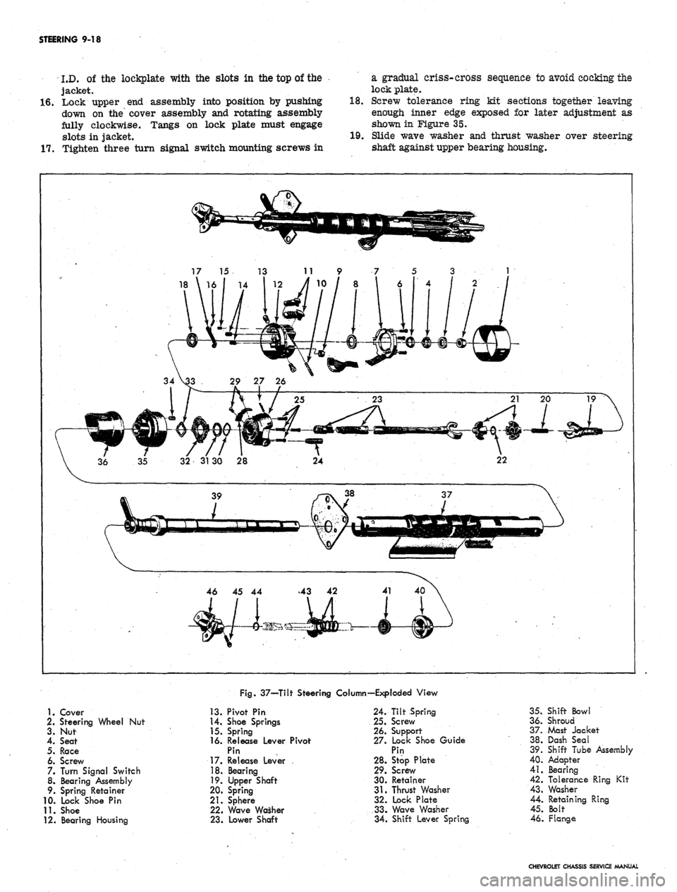
Fig.
37—Tilt Steering Column—Exploded View
1.
Cover
2.
Steering Wheel Nut
3. Nut
4.
Seat
5.
Race
6. Screw
7. Turn Signal Switch
8. Bearing Assembly
9. Spring Retainer
10.
Lock Shoe Pin
11.
Shoe
12.
Bearing Housing
13.
Pivot Pin
14.
Shoe Springs
15.
Spring
16.
Release Lever Pivot
Pin
17.
Release Lever
18.
Bearing
19.
Upper Shaft
20.
Spring
21.
Sphere
22.
Wave Washer
23.
Lower Shaft
24.
Tilt Spring
25.
Screw
26.
Support
27.
Lock Shoe Guide
Pin
28.
Stop Plate
29.
Screw
30.
Retainer
31.
Thrust Washer
32.
Lock Plate
33.
Wave Washer
34.
Shift Lever Spring
35.
Shift Bowl
36.
Shroud
37.
Mast Jacket
38.
Dash Seal
39.
Shift Tube Assembly
40.
Adapter
41.
Bearing
42.
Tolerance Ring Kit
43.
Washer
44.
Retaining Ring
45.
Bolt
46.
Flange
CHEVROLET CHASSIS SERVICE MANUAL
Page 459 of 659

STEERING 9-19
20.
21.
22.
23.
24.
25.
26.
27.
28.
Start "C" retaining ring over steering shaft taper.
Complete installation of retaining ring using snap
ring installer J-22659 as shown in Figure 28. Be
sure "C" retaining ring is completely seated into
steering shaft groove.
Remove any remaining looseness from internal col-
umn stack-up by unscrewing inner tolerance kit ring
section; then screw inner kit ring section back in
1/8 to 1/4 turn (fig. 36).
Touch the outer surface of the tolerance ring kit
.at
several locations with a hot soldering iron to melt
the threads of the inner and outer ring sections
together.
Place turn signal switch lever in position and se-
cure with screw. Screw hazard warning knob into
position.
If column is automatic and to be installed in a Chevy
II or Camaro, install the bulb and cap (fig. 33). Slide
the indicator into the 'shift bowl. Install dial and re-
tainer with screws removed during disassembly.
Install flange and clamp bolt at bottom of steering
shaft, if so equipped.
Remove column from vise and pull wires flat against
bottom of jacket. Snap wire protector and clip into
place.
If mesh cover was removed, wrap mesh cover around
jacket and secure with electricians or friction tape
/**% • *t 1*1* i '% •< n
Slide cancelling cam and
spring onto end of shaft.
upper bearing preload
Disassembly-Til* Column (Fig. 37)
NOTE:
This procedure covers disassembly and
assembly instructions for all tilt columns. Auto-
matic refers to a tilt column with a column
mounted, Powerglide shifting lever. Floor shift
. refers to' a tilt column taken from a vehicle with
conventional or Powerglide floor shift controls.
1.
Unsnap and remove wiring protector.
CAUTION: Secure column in bench vise for
service one of two ways shown in Figure 26.
Clamping column in vise in any other manner
will damage the column. If support fixture
J-22573 is not used, frequently check position
of column in vise jaws to insure column is not
working free of jawsT
2.
Clamp column in a bench vise as shown in Figure 26.
3.
Slide upper bearing preload spring and cancelling
cam off end of shaft.
Fig,
38—Removing Turn Signal Cover Using Tools
J-21486 and J-6585-1
Fig.
39—Removing Steering Shaft Bearing Lock Nut
Using Lock Nut Wrench j-22599
4.
On automatic columns removed from a Camaro, re-
move screws securing dial retainer to column and
remove retainer and dial (fig. 33). Slide pointer out
of bowl and remove pointer. Remove cap and bulb
from turn signal switch housing.
5. Remove turn signal lever retaining screw and re-
move lever. Unscrew and remove tilt release lever.
Push hazard warning knob in, unscrew and remove
knob.
6. On Automatic columns, drive out shift control lever
retaining pin and remove shift lever.
7. Assemble slide hammer Tool J-6585-1 to turn signal
cover remover Tool J-21486. Place cover remover
over turn signal cover, tighten clamp, and pull
cover from end of column with slide hammer (fig.
38).
8. Remove three turn signal switch mounting screws.
Note short length of secure removed from top
position.
9. Lift signal switch assembly off bearing housing and
allow to hang by the wires. On some columns, the
switch and wires can be removed at this time; re-
move switch and wires if possible. If switch and
wires cannot be removed, allow assembly to hang
by wires.
10.
Install tilt release lever and place column in full up
position. Remove tilt spring retainer using screw-
driver blade that just fits into slot opening. Insert
screwdriver in slot, press in approximately 3/16-
inch;
rotate retainer approximately 1/8 turn clock-
wise until ears align with grooves in housing, and
remove retainer and spring. Use care when remov-
ing spring, it is tightly compressed.
11.
Remove steering shaft bearing lock nut using lock nut
wrench Tool J-22599 (fig. 39). Remove inner race
•seat and inner "race.
12.
Remove two pivot pins from bearing housing using
pivot pin remover Tool J-21854 (fig. 40).
CHEVROLET CHASSIS SERVICE MANUAL
Page 476 of 659
STEERING 9-36
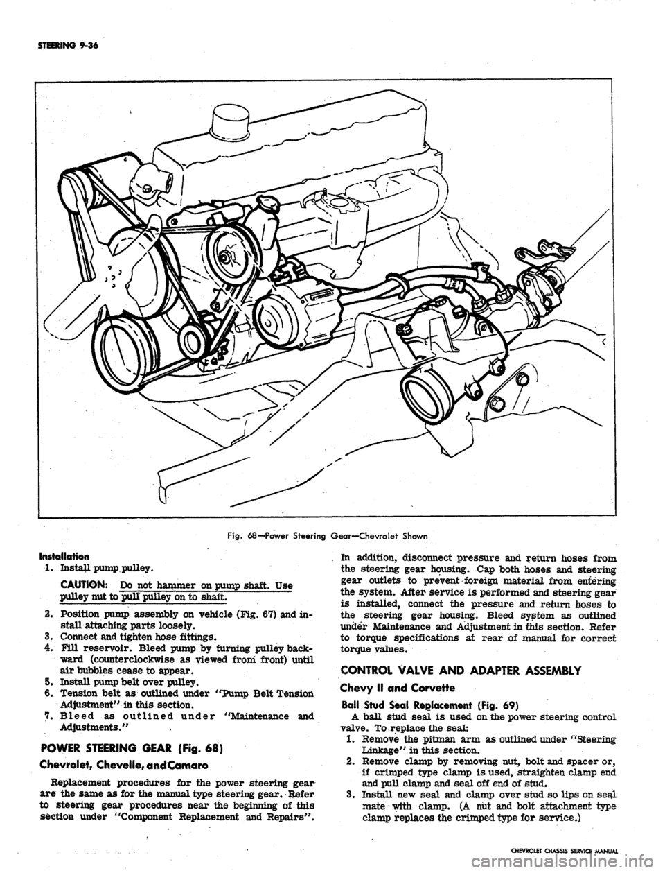
Fig.
68—Power Steering Gear—Chevrolet Shown
Installation
1.
Install pump pulley.
CAUTION: Do not hammer on pump shaft. Use
pulley nut to pull pulley on to shaft.
2.
Position pump assembly on vehicle (Fig. 67) and in-
stall attaching parts loosely.
3.
Connect and tighten hose fittings.
4.
Fill reservoir. Bleed pump by turning pulley back-
ward (counterclockwise as viewed from front) until
air bubbles cease to appear.
5. Install pump belt over pulley.
6. Tension belt as outlined under "Pump Belt Tension
Adjustment" in this section.
7. Bleed as outlined under "Maintenance and
Adjustments."
POWER STEERING GEAR (Fig. 68)
Chevrolet,
Chevelfe,
and Comoro
Replacement procedures for the power steering gear
are the same as for the manual type steering gear.
•
Refer
to steering gear procedures near the beginning of this
section under "Component Replacement and Repairs".
In addition, disconnect pressure and return hoses from
the steering gear housing. Cap both hoses and steering
gear outlets to prevent foreign material from entering
the system. After service is performed and steering gear
is installed, connect the pressure and return hoses to
the steering gear housing. Bleed system as outlined
under Maintenance and Adjustment in this section. Refer
to torque specifications at rear of manual for correct
torque values.
CONTROL VALVE AND ADAPTER ASSEMBLY
Chevy II and Corvette
Ball Stud Seal Replacement (Fig. 69)
A ball stud seal is used on the power steering control
valve. To replace the seal:
1.
Remove the pitman arm as outlined under "Steering
Linkage" in this section.
2.
Remove clamp by removing nut, bolt and spacer or,
if crimped type clamp is used, straighten clamp end
and pull clamp and seal off end of stud.
3.
Install new seal and clamp over stud so lips on seal
mate with clamp. (A nut and bolt attachment type
clamp replaces the crimped type for service.)
CHEVROLET CHASSIS
SERVICE
MANUAL
Page 516 of 659
ELECTRICAL-BODY AND CHASSIS 12-4
b.
hand lamp until the string is positioned over the
crossarm centerline. Turn the screw clockwise
in making the final adjustment to take up play in
the headlamp mechanism.
Repeat the above procedure on the right-hand
lamp to complete the horizontal adjustment of the
headlamps.
VERTICAL ADJUSTMENT
8. a. Numeral "2" (fig. 5) should appear in the "down"
window of each aimer. If not, loosen knob at
underside of aimer arm and slide back and forth
until the numeral does appear.
NOTE:
This setting will give a 2" drop of the
headlamp high beam spot centerline on a screen
placed 25 feet forward of the vehicle. Check
state laws for proper vertical setting.
b.
Turn headlamp vertical aim screw (fig. 5) on left-
hand unit counter-clockwise until the bubble is at
the inner end of the glass tube. Then turn screw
clockwise until bubble is centered in tube.
c. Repeat this procedure on right-hand headlamp
unit to complete vertical adjustment of lamps.
9. Recheck the string at the ends of each crossarm for
correct setting and the bubble on each aimer for
centered position.
10.
Remove the aimers by pulling on the suction cup tabs
through the openings in the aimers (fig. 6).
11.
With headlamps properly aimed, replace headlamp
bezels.
HOW TO SELECT A LEVEL AIMING AREA
1.
Select area you believe to be level.
2.
Remove headlamp bezels and install Aimers on each
headlamp (fig. 3) making sure aiming lugs engage
smoooth inner ring of the Aimer.
"
To install Aimer,
press firmly on the knob extending out from the cen-
ter of the Aimer base. This forces the suction cup
into place on the Sealed Beam unit.:
3.
Loosen the slider knob beneath the aimer arm and
set the numeral "2" in the DOWN view window (fig.
7).
Back vertical lamp adjustment out on each lamp
until bubble is outside of black line of vial, then cen-
ter bubble in between black line of vial by turning
clockwise.
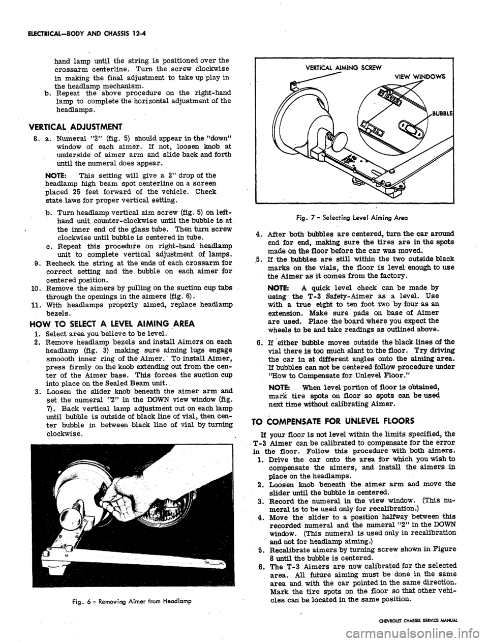
VERTICAL AIMING SCREW
VIEW WINDOWS
BUBBLE
Fig.
6 - Removing Aimer from Headlamp
Fog.
7- Selecting Level Aiming Area
4.
After botli bubbles are centered, turn the car around
end for end, making sure the tires are in the spots
made on the floor before the car was moved.
.5.
If the bubbles are still within the two outside black
marks on the vials, the floor is level enough to use
the Aimer as it comes from the factory.
NOTE:
A quick level check can be made by
using the T-3 Safety-Aimer as a level. Use
with a true eight to ten foot two by four as an
extension. Make sure pads on base of Aimer
are used. Place the board where you expect the
wheels to be and take readings as outlined above.
6. If either bubble moves outside the black lines of the
vial there is too much slant to the floor. Try driving
the car in at different angles onto the aiming area.
If bubbles can
not
be centered follow procedure under
"How to Compensate for Unlevel Floor."
NOTE:
When level portion of floor is obtained,
mark tire spots on floor so spots can be used
next time without calibrating Aimer.
TO COMPENSATE FOR UNLEVEL FLOORS
If your floor is not level within the limits specified, the
T-3 Aimer can be calibrated to compensate for the error
in the floor. Follow this procedure with both aimers.
1.
Drive the car onto the area for which you wish to
compensate the aimers, and install the aimers in
place on the headlamps.
2.
Loosen knob beneath the aimer arm and move the
slider until the bubble is centered.
3.
Record the numeral in the view window. (This nu-
meral is to be used only for recalibration.)
4.
Move the slider to a position halfway between this
recorded numeral and the numeral "2" in the
DOWN
window. (This numeral is used only in recalibration
and not for headlamp aiming.)
5.
Recalibrate aimers by turning screw shown in Figure
8 until the bubble is centered.
6. The T-3 Aimers are now calibrated for the selected
area. All future aiming must be done in the same
area and with the car pointed in the same direction.
Mark the tire spots on the floor so that other vehi-
cles can be located in the same position.
CHEVROLET CHASSIS SERVICE MANUAL
Page 528 of 659
ELECTRICAL-BODY AND CHASSIS 12-16
BACK-UP LAMP CONN.
CONSOLE CTSY
LAMP CONN
CLOCK CONN
NEUTRAL SAFETY SWITCH
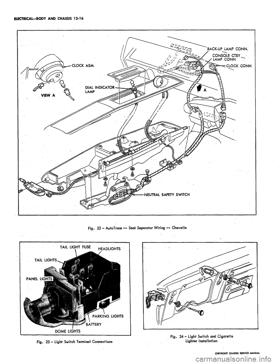
Fig.
22 - AutoTrans — Seat- Separator Wiring — Chevelle
TAIL
PANEL Ll<
J
TAIL
LIGHTS ^^g
9
""TUtflll -^ ""
DOME
LIGHT
r
•I
m
/
LIGHTS
FUSE HEADLIGHTS
9R
jl PARKING LIGHTS
*^ R ATTPRY
Fig.
23 - Light Switch Terminal Connections
Fig.
24 - Light Switch and Cigarette
Lighter Installation
CHEVROLET CHASSIS SERVICE MANUAL
Page 531 of 659

ELECTRICAL-BODY AND CHASSIS 12-19
VIEW A
•CONTACT SUPPORT
DRIVE SLOT IN LINE
WITH HOLE IN SWITCH
PAWL
CONTACT POINT B
CONTACT SUPPORT
DRIVE SLOT IN LINE
WITH HOLE IN SWITCH
FLOOR SHIFT
(EXCEPT CAMARO)
COLUMN SH
Fig.
31 - Neutral Safety Switches
PARKING BRAKE ALARM SWITCH REPLACEMENT
Corvette (Fig. 33)
1.
Remove seat belt retainer and parking brake cover
assembly from center console.
2.
Disconnect wire from brake alarm switch.
3.
Remove retaining screw and switch from
reinforcement.
4.
Position new switch to reinforcement and install re-
taining screw.
5. Connect switch wire and check operation of switch.
6. Install cover and seat belt retainer assembly.
Chevrolet, Chevelle, Chevy II and Camaro (Fig. 34)
1.
Disconnect wiring connector at switch terminal.
2.
Remove nut and lock washer or retaining bolt and
disengage switch from brace.
3.
To install, reverse removal procedure.
INSTRUMENT PANEL COMPARTMENT
LAMP/SWITCH REPLACEMENT
1.
Disconnect battery ground cable.
2.
Reach into glove box, depress bulb in end of switch
and turn counterclockwise to remove bulb.
3..
Remove switch from socket. Carefully detach wire
and terminal from switch.
NOTE:
On some model switches, the wire and
terminal cannot be detached from the switch
making it necessary to cut and splice the switch
wire.
4.
Insert wire and terminal into new switch.
5. Push switch into place and install bulb by setting it in
place, depressing and turning it clockwise.
CIGARETTE LIGHTER REPLACEMENT
Chevrolet, Chevy II, Camaro and Corvette (Fig. 23)
1.
Disconnect battery ground cable.
2.
Disconnect wire connector at rear of lighter unit
under dash.
3.
Remove retainer from rear of housing assembly and
disengage lighter unit from panel.
4.
To install, reverse removal procedure.
Chevelle (Fig. 35)
1.
Disconnect battery ground cable.
CHEVROLET CHASSIS SERVICE MANUAL
Page 533 of 659
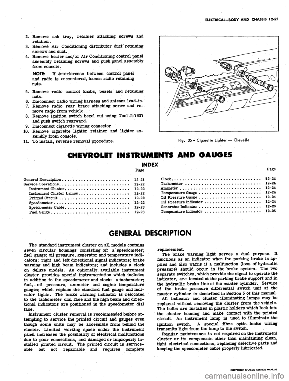
ELECTRICAL-BODY AND CHASSIS 12-21
2.
Remove ash tray, retainer attaching screws and
retainer.
3.
Remove Air Conditioning distributor
duct'
retaining
screws and duct.
4.
Remove heater and/or Air Conditioning control panel
assembly retaining screws and push panel assembly
from console.
NOTE:
If interference between control panel
and radio is encountered, loosen radio retaining
nuts.
5. Remove radio control knobs, bezels and retaining
nuts.
6. Disconnect radio wiring harness and antenna lead-in.
7. Remove radio rear brace attaching screw and re-
move ra(Jio from vehicle.
8. Remove ignition switch bezel nut using Tool J-7607
and push switch rearward.
9. Disconnect cigarette wiring connector.
10.
Remove cigarette lighter retainer and lighter as-
sembly from console.
11.
To install, reverse removal procedure.
Fig.
35 - Cigarette Lighter — Chevelle
CHEVROLET INSTRUMENTS AND GAUGES
INDEX
Page
General Description 12-21
Service Operations 12-22
Instrument Cluster........................ 12-22
Instrument Cluster Lamps 12-22
Printed Circuit .
* •
12-22
Speedometer 12-22
Speedometer Cable 12-23
Fuel Gauge 12-23
Page
Clock 12-24
Tachometer 12-24
Ammeter . . 12-24
Temperature Gauge 12-24
Oil Pressure Gauge 12-24
Oil Pressure Indicator 12-24
Generator Indicator 12-26
Temperature Indicator 12-26
GENERAL DESCRIPTION
The standard instrument cluster on all models contains
seven circular housings consisting of: a speedometer;
fuel gauge; oil pressure, generator and temperature indi-
cators; right and left directional signal indicators; brake
warning and high beam indicators; and includes a clock
on deluxe models. An optionally available instrument
cluster provides special instrumentation which includes
in addition to the speedometer and clock: a tachometer;
fuel, oil pressure, ammeter and engine temperature
gauges; which replace the standard fuel gauge and indi-
cator lights. The brake warning indicator is relocated
to the tachometer dial face and the high beam and direc-
tional indicators are positioned in the speedometer dial
face.
Instrument cluster removal is recommended before at-
tempting to service the printed circuit and gauges even
though some units may be accessible from behind the
cluster. Limited working space under the instrument
panel increases the possibility of electrical malfunctions
due to poor connections, and damaged or improperly in-
stalled printed circuit. The printed circuit is service-
able but not repairable and requires complete
replacement.
The brake warning light serves a dual purpose. It
functions as an indicator when the parking brake is ap-
plied and also warns if a malfunction (loss of hydraulic
pressure) should occur in the brake system. The two
separate switches, which provide the signal to operate the
indicator, are located at the parking brake support and in
the hydraulic brake line at the master cylinder. Service
of the brake pressure, differential switch unit at the
master cylinder is described in Section 5 of this manual.
All indicator and cluster illumihating lamps may be
replaced without removing the cluster from the vehicle.
The bulbs are installed in plastic holders which lock into
the cluster housing and make contact with the printed
circuit. An instrument lamp is used to illuminate the
ignition switch. A special fibre optic lucite wiring
transmits light from the lamp to the switch.
Regular maintenance is not required on the instrument
cluster or its components other than maintaining clean,
tight electrical connections, replacing defective parts and
keeping the speedometer cable properly lubricated.
CHEVROLET CHASSIS SERVICE MANUAL
Page 534 of 659
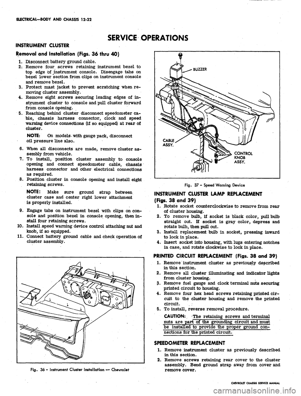
ELECTRICAL-BODY AND CHASSIS 12-22
SERVICE OPERATIONS
INSTRUMENT CLUSTER
Removal and Installation (Figs. 36 thru 40)
I. Disconnect battery ground cable.
2:
Remove four screws retaining instrument bezel to
top edge of instrument console. Disengage tabs on
bezel lower section from clips on instrument console
and remove bezel.
3.
Protect mast jacket to prevent scratching when re-
moving cluster assembly.
4.
Remove eight screws securing leading edges of in-
strument cluster to console and pull cluster forward
from console opening.
5. Reaching behind cluster disconnect speedometer ca-
ble,
chassis harness connector, clock and speed
warning device connections (if so equipped) at rear of
cluster.
NOTE:
On models- with gauge pack, disconnect
oil pressure line also.
6. When all disconnects are made, remove cluster as-
sembly from vehicle.
7. To install, position cluster assembly to console
opening and connect speedometer cable, chassis
harness connector and other electrical connections
as required.
8. Position cluster in console opening and install eight
retaining screws.
NOTE:
Make sure ground strap between
cluster case and center right lower attachment
is properly installed.
9. Engage tabs on instrument bezel with clips on con-
sole and position bezel in console opening, then in-
stall four retaining screws.
10.
Install speed warning device control attaching nut and
knob,
if so equipped.
II.
Connect battery ground cable and check operation of
cluster assembly.
Fig. 36 - Instrument Cluster Installation — Chevrolet
Fig. 37 - Speed Warning Device
INSTRUMENT CLUSTER LAMP REPLACEMENT
(Figs.
38 and 39)
1.
Rotate socket counterclockwise to remove from rear
of cluster housing.
2.
To remove bulb, if socket is black color, pull bulb
straight out. If socket is gray color, depress and
rotate bulb, then pull out.
3.
Install replacement bulb in socket, pressing inward
to lock in place.
4.
Insert socket into housing, with lugs entering notches
in case, and rotate clockwise to lock in place.
PRINTED CIRCUIT REPLACEMENT (Figs. 38 and 39)
1.
Remove instrument cluster as previously described
in this section.
2.
Remove all cluster illuminating and indicator lights
from cluster housing.
3.
Remove fuel gauge and clock terminal nuts securing
printed circuit to housing.
4.
Remove four hex head screws retaining printed cir-
cuit to the cluster housing and remove the printed
circuit. . .
5. To install, reverse removal procedure.
CAUTION:. The retaining screws and terminal
nuts are part of the grounding circuit and must
be installed to provide the proper ground con-
nections for the printed circuit.
SPEEDOMETER
REPLACEMENT
1.
Remove instrument cluster as previously described
in this section.
2.
Remove screws retaining rear cover to the cluster
assembly. Bend ground strap away from cover and
remove cover.
CHEVROLET CHASSIS SERVICE MANUAL
Page 535 of 659
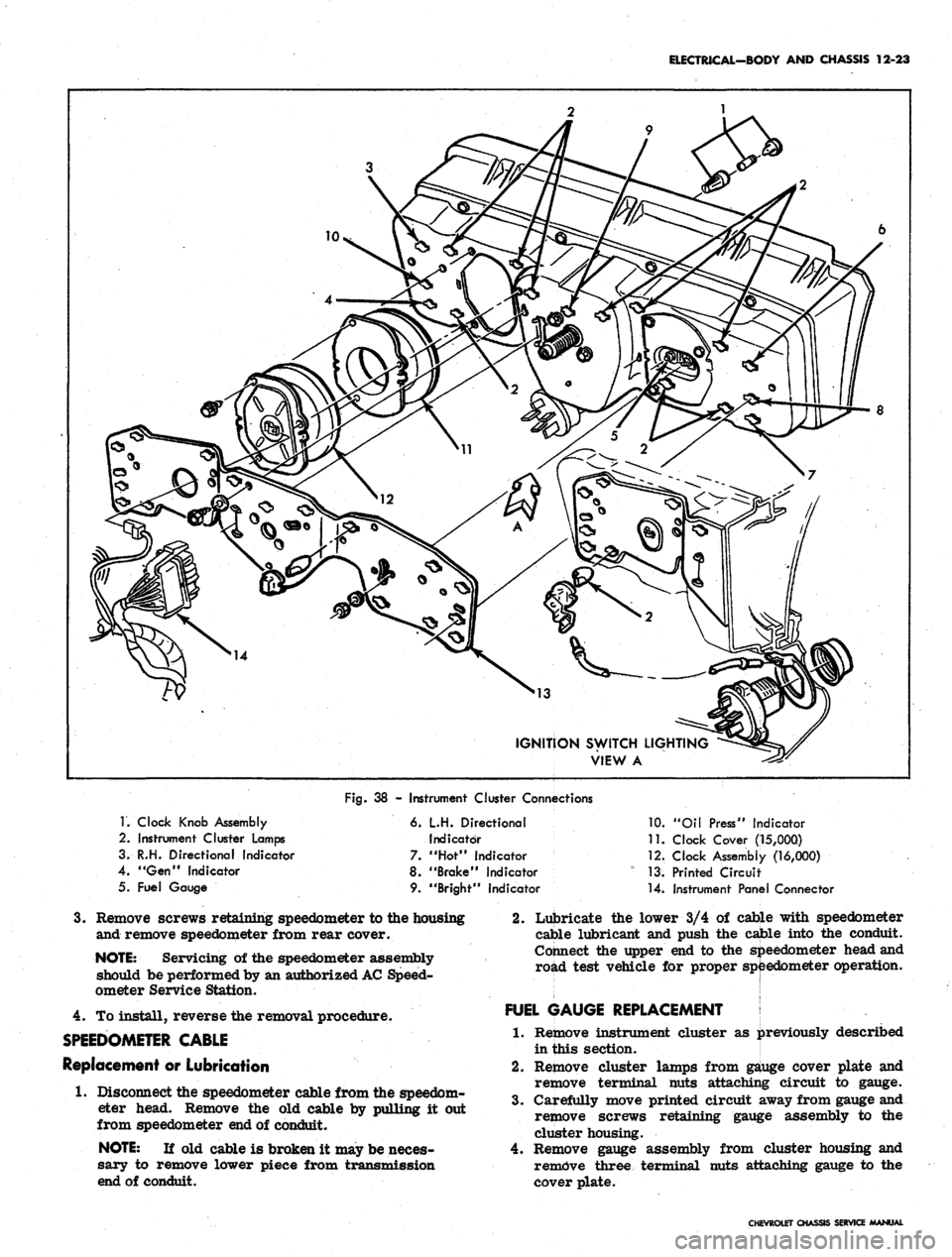
ELECTRICAL-BODY AND CHASSIS 12-23
IGNITION SWITCH LIGHTING
VIEW A
1.
Clock Knob Assembly
2.
Instrument Cluster Lamps
3. R.H. Directional Indicator
4.
"Gen'*
Indicator
5. Fuel Gauge
Fig.
38 - Instrument Cluster Connections
6. L.H. Directional
Indicator
7. "Hot" indicator
8. "Brake" Indicator
9. "Bright" Indicator
10.
"Oil Press" Indicator
11.
Clock Cover (jl5,0OQ)
12.
Clock Assembly (16,000)
1.3; Printed Circuit
14.
Instrument Panel Connector
3.
Remove screws retaining speedometer to the housing
and remove speedometer from rear cover.
NOTE:
Servicing of the speedometer assembly
should be performed by an authorized
AC
Speed-
ometer Service Station.
4.
To install, reverse the removal procedure.
SPEEDOMETER CABLE
Replacement or Lubrication
1.
Disconnect the speedometer cable from the speedom-
eter head. Remove the old cable by pulling it out
from speedometer end of conduit.
NOTE:
If old cable is broken it may be neces-
sary to remove lower piece from transmission
end of conduit.
2.
Lubricate the lower 3/4 of cable with speedometer
cable lubricant and push the cable into the conduit.
Connect the upper end to the speedometer head and
road test vehicle for proper speedometer operation.
FUEL GAUGE REPLACEMENT
1.
Remove instrument cluster as previously described
in this section.
2.
Remove cluster lamps from gauge cover plate and
remove terminal nuts attaching circuit to gauge.
3.
Carefully move printed circuit away from gauge and
remove screws retaining gauge assembly to the
cluster housing.
4.
Remove gauge assembly from cluster housing and
remove three terminal nuts attaching gauge to the
cover plate.
CHEVROLET CHASSIS SERVICE MANUAL
Page 536 of 659
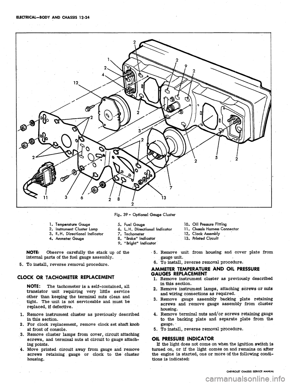
ELECTRICAL-BODY AND CHASSIS 12-24
1.
Temperature Gauge
2.
Instrument Cluster Lamp
3.
R.H. Directional Indicator
4.
Ammeter Gauge
Fig. 39- Optional Gauge Cluster
5. Fuel Gauge
6. L.H. Directional Indicator
7. Tachometer
8. "Brake" Indicator
9. "Bright" Indicator
10.
Oil Pressure Fitting
11.
Chassis Harness Connector
12.
Clock Assembly
13.
Printed Circuit
NOTE:
Observe carefully the stack up of the
internal parts of the fuel gauge assembly.
5. To install, reverse removal procedure.
CLOCK OR TACHOMETER REPLACEMENT
NOTE:
The tachometer is a self-contained, all
transistor unit requiring very little service
other than keeping the terminal nuts clean and
tight. The unit is not serviceable and must be
replaced, if defective.
1.
Remove instrument cluster as previously described
in this section.
2.
For clock replacement, remove clock set shaft knob
at front of console.
3.
Remove cluster lamps from cover, circuit attaching
screws, and terminal nuts at circuit to gauge attach-
ing points.
4.
Move printed circuit away from gauge and remove
screws retaining
•_
gauge or clock to the cluster
housing.
•5.
Remove unit, from housing and cover plate from
gauge unit.
6/To install, reverse removal procedure.
AMMETER TEMPERATURE AND OIL PRESSURE
GAUGES REPLACEMENT
1.
Remove instrument cluster as previously described
iii this section.
2.
Remove instrument lamps, attaching screws or nuts
and wiring connections as required.
3.
Remove gauge assembly backing plate retaining
screws and remove gauge assembly from cluster
housing.
4.
Remove terminal nuts and/or screws retaining gauge
to the backing plate and separate plate from the
gauge.
•
5. To install, reverse removal procedure.
OIL PRESSURE INDICATOR
If the light does not come on when the ignition switch is
turned on, or if the light comes on and remains on after
the engine is started, one or more of the following condi-
tions is indicated:
CHEVROLET CHASSIS SERVICE MANUAL