steering wheel CHEVROLET CAMARO 1967 1.G Chassis Service Manual
[x] Cancel search | Manufacturer: CHEVROLET, Model Year: 1967, Model line: CAMARO, Model: CHEVROLET CAMARO 1967 1.GPages: 659, PDF Size: 114.24 MB
Page 446 of 659
STEERING 9-6
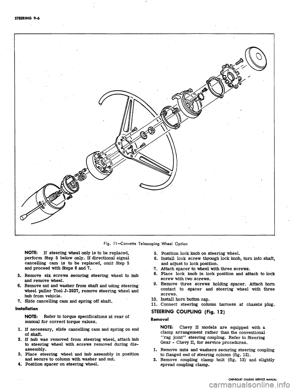
Fig.
11
—Corvette Telescoping Wheel Option
5.
7.
NOTE:
If steering wheel only is to be replaced,
perform Step 5 below only. If directional signal
cancelling cam is to be replaced, omit Step 5
and proceed with Steps 6 and 7.
Remove six screws securing steering wheel to hub
and remove wheel.
Remove nut and washer from shaft and using steering
wheel puller Tool J-2927, remove steering wheel and
hub from vehicle.
Slide cancelling cam and spring off shaft.
Installation
NOTE:
Refer to torque specifications at rear of
manual for correct torque values.
1.
If necessary, slide cancelling cam and spring on end
of shaft.
2.
If hub was removed from steering wheel, attach hub
to steering wheel with screws removed during dis-
assembly.
3.
Place steering wheel and hub assembly in position
and secure to column with washer and nut.
4.
Position spacer on steering wheel.
5. Position lock knob on steering wheel.
6. Install lock screw through lock knob, turn into shaft,
and adjust to lock position.
7. Attach spacer to wheel with three screws.
8. Place lock knob in lock position and attach to lock
screw with two screws.
9. Remove three screws holding spacer. Attach horn
contact to spacer and steering wheel with three
screws.
10.
Install horn button cap.
11.
Connect steering column harness at chassis plug.
STEERING COUPLING (Fig. 12)
Removal
NOTE:
Chevy n models are equipped with a
clamp arrangement rather than the conventional
"rag joint" steering coupling. Refer to Steering
Gear - Chevy II, for service procedures.
1.
Remove nuts and washers securing steering coupling
to flanged end of steering column (fig. 12).
2.
Remove coupling clamp bolt (fig. 12) and slightly
spread coupling clamp.
CHEVROLET CHASSIS SERVICE MANUAL
Page 450 of 659

STEERING 9-10
SECTOR SHAFT SEAL REPLACEMENT
A faulty seal may be replaced without removal of
steering gear from car by removing pitman arm as out-
lined under Maintenance and Adjustments--Steering Gear
Adjustments and proceed as follows:
1.
Loose lash adjuster lock nut and turn lash adjuster
screw several turns counterclockwise.
2.
Remove three cap screws holding side cover to gear
bushing.
3.
Pull side cover and sector shaft from gear housing
as a unit. Do not separate side cover from sector
shaft.
4.
Pull sector shaft seal from gear housing using
hooked tool or pliers.
5. Coat new seal with chassis grease and position in
sector shaft bore.
6. Place a socket or piece of pipe of suitable diameter
on top of seal and drive seal into bore by tapping
pipe or socket with soft hammer.
7. Install sector shaft side cover assembly, being care-
ful not to damage new seal with splines on end of
shaft; splines may be wrapped with a few turns of
tape to prevent this.
8. Install new side cover gasket and align side cover on
gear housing and install cap screw.
9. Perform steering gear adjustment and install pitman
arm as outlined under Maintenance and Adjustments.
STEERING COLUMN
All models are equipped with new energy absorbing
steering columns. The columns are of five basic designs
as follows:
1.
Syncromesh. The syncromesh column is used on
models with standard, column mounted, conventional
shift levers. The shift tube, within the outer mast
jacket, includes two lower shift levers for connection
to the transmission control linkage.
2.
Automatic and floor shift. This column is used on
models equipped with column mounted powerglide
shift levers, or models with floor shift. If the ve-
hicle has the column mounted powerglide shift con-
trol, the inner shift tube has a single lower shift
lever for connection to the transmission control
linkage. On floor shift models, no lower shift levers
are present on the shift tube.
3.
Tilt wheel option. The upper end and steering shaft
of this column is specially designed to accommodate
the optional tilt steering wheel.
4.
Standard Corvette Column. The standard Corvette
column is similar in design to the Automatic and
Floor Shift column used on other models, except
no shift tube is used. Other differences are pointed
out in the disassembly and assembly procedures for
Standard Corvette column.
5. Telescopic wheel option. The upper end and steering
shaft of this column is specially designed to ac-
commodate the optional telescoping steering wheel.
To perform service procedures on steering column
upper end components, it is not necessary to remove the
column from the vehicle. The steering wheel, horn com-
ponents, turn signal switch, upper housing with bearing,
shift control lever, hazard warning knob, and upper shift
bowl may all be removed with the column remaining in
the vehicle. When servicing the above components, omit
the removal procedure and proceed with the applicable
disassembly procedures. Because of the numerous dif-
ferences in steering column types, be sure to refer to the
set of instructions below which apply to the exact column
to be serviced:
CAUTION: The outer mast jacket, shift tube, _
steering shaft, and instrument panel column
mounting b
racket
are designed as energy ab-
sorbing units. Because of the design of these
components, it is absolutely necessary to handle
the column with care when performing any serv-
ice operation required. Avoid hammering, jar-
ring, dropping, or leaning on any portion of the
column.
Removal
1.
Disconnect steering column harness at connector.
Disconnect neutral safety switch and back-up lamp
switch connectors if so equipped.
Remove steering wheel as outlined in this section.
Remove nuts and washers securing flanged end of
column to steering gear. On Chevy H models, re-
move nut and clamp bolt securing lower end of steer-
ing column to steering gear.
Disconnect transmission control linkage, if so
equipped, from lower column shift tube, levers.
Chevrolet and Chevy II only: Remove screws at-
taching upper and lower mast jacket covers together.
On Chevrolet, remove screws attaching lower cover
to instrument panel (figs. 15 and 18). Remove lower
cover.
Chevelle only: Remove screws securing mast jacket
trim cover to instrument panel and remove cover
(fig. 15).
Corvette, only: Remove screws securing escutcheon
to instrument panel. Remove screws securing upper
and lower covers together and remove covers.
On Chevrolet and Chevelle columns with Powerglide
shift levers, loosen set screw at six o'clock position
at bottom of column and remove the transmission
shift indicator pointer (fig. 15).
9. Chevrolet only (fig. 19):
a. Remove screws securing cover trim to dash
panel and remove cover trim.
2.
3.
4.
5.
6.
7.
8.
Fig.
18—Mast Jacket Cover Attachments—Chevy II
CHEVROLET CHASSIS SERVICE MANUAL
Page 452 of 659
STEERING 9-12
1.
Steering Wheel Nut
2i Screw
3. Retaining Ring
4.
Thrust Washer
5. Wave Washer
6. Turn Signal Switch
7. Upper Bearing and
Housing Assembly
8. Cover
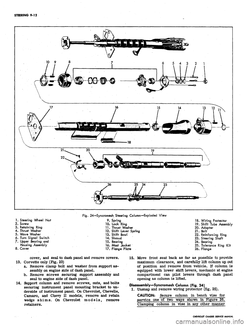
Fig.
24—Syncromesh Steering Column—Exploded View
9. Spring
1.0. Lock Ring
11.
Thrust Washer
12.
Shift Lever Spring
13.
Shift Bowl
14.
Shroud
15.
Bearing
16.
Mast Jacket
17.
Flange Plate
18.
Wiring Protector
19.
Shift Tube Assembly
20.
Adapter
21.
Bolt
22.
Reinforcing Ring
23.
Steering Shaft
24.
Bearing
25.
Tolerance Ring Kit
26.
Flange
cover, and seal to dash panel and remove covers.
13.
Corvette only (Fig. 23)
a. Remove clamp bolt and washer from support as-
sembly on engine side of dash panel.
b.
Remove screws securing support assembly and
seal to engine side of dash panel.
14.
Support column and remove screws, nuts, and bolts
securing instrument panel mounting bracket to un-
derside of instrument panel. On Chevrolet, Chevelle,
Camaro, and Chevy II models, remove and retain
wedge shims. On Chevrolet models, remove
retainers.
15.
Move front seat back as far as possible to provide
maximum clearance, and carefully lift column up out
of position and remove from vehicle. If column is
equipped with lower shift levers, mechanic at engine
compartment can pilot levers through dash panel
opening as column is lifted.
Disassembly'—Syncromesh Column (Fig. 24)
1.
Unsnap and remove wiring protector (fig. 25).
CAUTION: Secure column in bench vise for
service one of two ways shown in Figure 26.
Clamping column in vise in any other manner
CHEVROLET CHASSIS SERVICE MANUAL
Page 455 of 659
STEERING 9-15
jacket and loosely secure using the three bolts re- 8.
moved during disassembly.
Place a 0.005 maximum shim on each side of the 9.
shaft, between either one of the shift levers and the
spacer (fig. 31). 10.
Using spanner wrench J-22568 installed in spanner
holes in adapter, rotate the.adapter clockwise until
the shift levers are bottomed out (fig. 31). Bottom
the adapter against the jacket while rotating to re-
move end play. 11.
Tighten the three adapter bolts. Remove the two
0.005 shims.
Insert the steering shaft assembly into position
through the lower end of the jacket.
Attach the back-up lamp switch loosely to the jacket
using the same nuts removed during disassembly.
Install these nuts loosely, switch will be tightened to
the jacket when column is installed in vehicle and
shift levers are aligned.
If upper shift lever spring was removed, press a
10 9 8
6 5 4 3 2 1
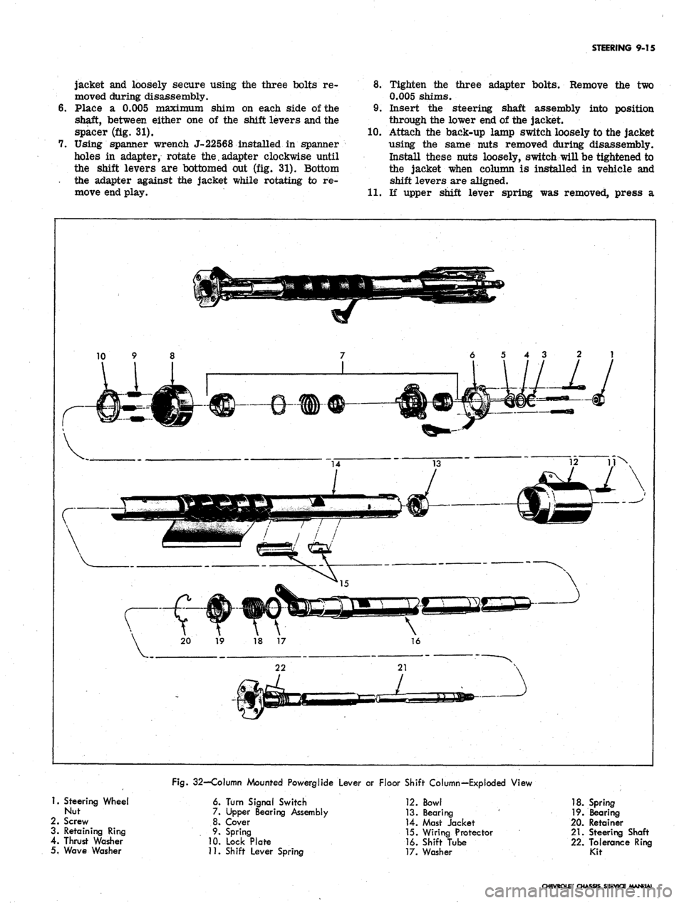
Fig.
32—Column Mounted Powerglide Lever or Floor Shift Column—Exploded View
1.
Steering Wheel
Nut
2.
Screw
3. Retaining Ring
4.
Thrust Washer
5. Wave Washer
6. Turn Signal Switch
7. Upper Bearing Assembly
8. Cover
9. Spring
10.
Lock Plate
11.
Shift Lever Spring
12.
Bowl
13.
Bearing
14.
Mast Jacket
15.
Wiring Protector
16.
Shift Tube
17.
Washer
18.
Spring
19.
Bearing
20.
Retainer
21.
Steering Shaft
22.
Tolerance Ring
Kit
CHEVROLET CHASSIS SERVICE MANUAL
Page 458 of 659
STEERING 9-18
I.D. of the lockplate with the slots in the top of the
jacket.
16.
Lock upper end assembly into position by pushing 18.
down on the cover assembly and rotating assembly
fully clockwise. Tangs on lock plate must engage
slots in jacket. 19.
17.
Tighten three turn signal switch mounting screws in
a gradual criss-cross sequence to avoid cocking the
lockplate.
Screw tolerance ring kit sections together leaving
enough inner edge exposed for later adjustment as
shown in Figure 35.
Slide wave washer and thrust washer over steering
shaft against upper bearing housing.
17 15 13 11 9 7 5 3
34 V33 29 27 26
36 35 32 3130 28
46 45 44 -43 42
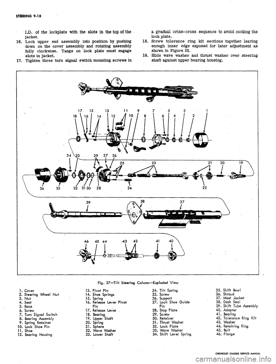
Fig.
37—Tilt Steering Column—Exploded View
1.
Cover
2.
Steering Wheel Nut
3. Nut
4.
Seat
5.
Race
6. Screw
7. Turn Signal Switch
8. Bearing Assembly
9. Spring Retainer
10.
Lock Shoe Pin
11.
Shoe
12.
Bearing Housing
13.
Pivot Pin
14.
Shoe Springs
15.
Spring
16.
Release Lever Pivot
Pin
17.
Release Lever
18.
Bearing
19.
Upper Shaft
20.
Spring
21.
Sphere
22.
Wave Washer
23.
Lower Shaft
24.
Tilt Spring
25.
Screw
26.
Support
27.
Lock Shoe Guide
Pin
28.
Stop Plate
29.
Screw
30.
Retainer
31.
Thrust Washer
32.
Lock Plate
33.
Wave Washer
34.
Shift Lever Spring
35.
Shift Bowl
36.
Shroud
37.
Mast Jacket
38.
Dash Seal
39.
Shift Tube Assembly
40.
Adapter
41.
Bearing
42.
Tolerance Ring Kit
43.
Washer
44.
Retaining Ring
45.
Bolt
46.
Flange
CHEVROLET CHASSIS SERVICE MANUAL
Page 462 of 659
STEERING 9-22
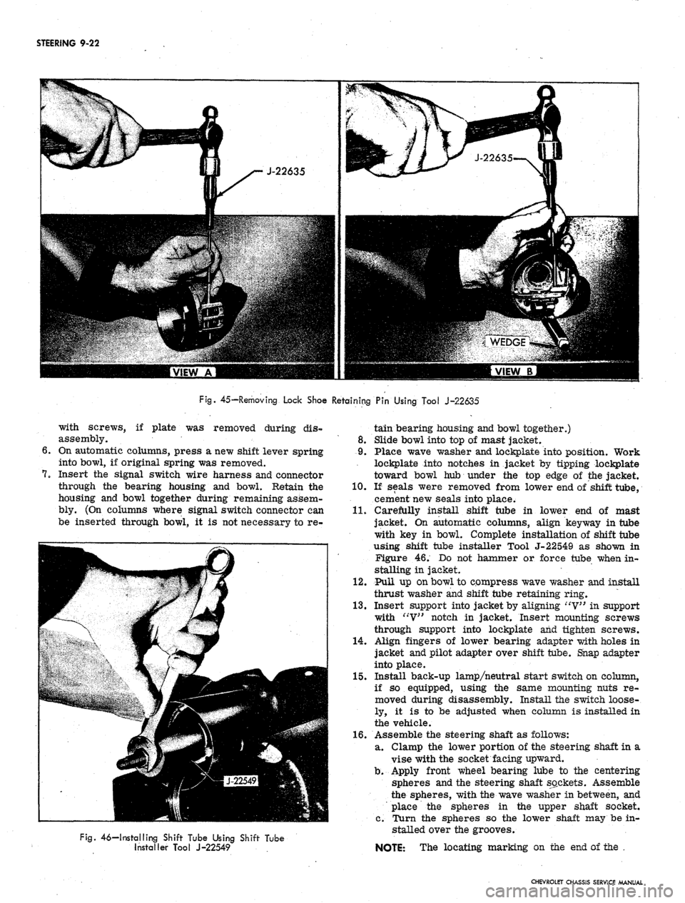
Fig.
45—Removing Lock Shoe Retaining Pin Using Tool J-22635
with screws, if plate was removed during dis-
assembly.
On automatic columns, press a new shift lever spring
into bowl, if original spring was removed.
Insert the signal switch wire harness and connector
through the bearing housing and bowl. Retain the
housing and bowl together during remaining assem-
bly. (On columns where signal switch connector can
be inserted through bowl, it is not necessary to re-
Fig.
46—Installing Shift Tube Using Shift Tube
Installer Tool J-22549
tain bearing housing and bowl together.)
8. Slide bowl into top of mast jacket.
9. Place wave washer and lockplate into position. Work
lockplate into notches in jacket by tipping lockplate
toward bowl hub under the top edge of the jacket.
10.
If seals were removed from lower end of shift tube,
cement new seals into place.
11.
Carefully install shift tube in lower end of mast
jacket. On automatic columns, align key way in tube
with key in bowl. Complete installation of shift tube
using shift tube installer Tool J-22549 as shown in
Figure 46. Do not hammer or force tube when in-
stalling in jacket.
12.
Pull up on bowl to compress wave washer and install
thrust washer and shift tube retaining ring.
13.
Insert support into jacket by aligning "V" in support
with "V" notch in jacket. Insert mounting screws
through support into lockpiate and tighten screws.
14.
Align fingers of lower bearing adapter with holes in
jacket and pilot adapter over shift tube. Snap adapter
into place.
15.
Install back-up lamp/neutral start switch on column,
if so equipped, using the same mounting nuts re-
moved during disassembly. Install the switch loose-
ly, it is to be adjusted when column is installed in
the vehicle.
16.
Assemble the steering shaft as follows:
a. Clamp the lower portion of the steering shaft in a
vise with the socket facing upward.
b.
Apply front wheel bearing lube to the centering
spheres and the steering shaft sockets. Assemble
the spheres, with the wave washer in between, and
place the spheres in the upper shaft socket.
c. Turn the spheres so the lower shaft may be in-
stalled over the grooves.
NOTE: The locating marking on the end of the .
CHEVROLET CHASSIS SERVICE MANUAL
Page 464 of 659
STEERING
9-24
1.
Upper Flange
2.
Retaining Screws
3.
Mast Jacket
4.
Wiring Protector
5. Bearing
6. Signal Switch
. Screws
7.
Turn Signal Switch
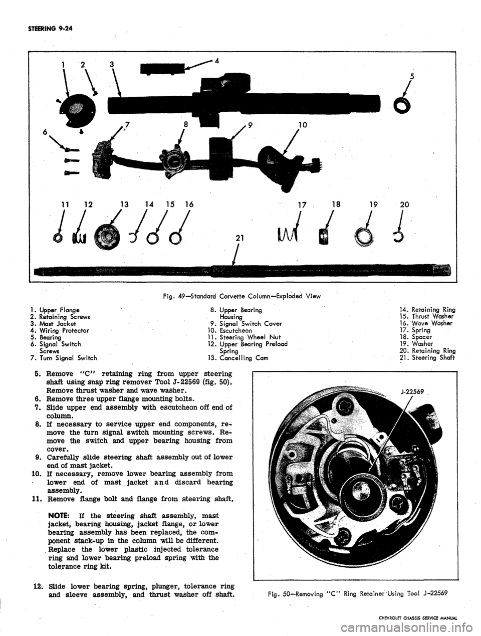
Fig.
49—Standard Corvette Column—Exploded View
8.
Upper Bearing
Housing
9.
Signal Switch Cover
10.
Escutcheon
11.
Steering Wheel Nut
12.
Upper Bearing Preload
Spring
13.
Cancelling Cam
5. Remove "C" retaining ring from upper steering
shaft using snap ring remover Tool J-22569 (fig. 50).
Remove thrust washer and wave washer.
6. Remove three upper flange mounting bolts.
7. Slide upper end assembly with escutcheon off end of
column.
8. If necessary to service upper end components, re-
move the turn signal switch mounting screws. Re-
move the switch and upper bearing housing from
cover.
9. Carefully slide steering shaft assembly out of lower
end of mast jacket.
10.
If necessary, remove lower bearing assembly from
lower end of mast jacket and discard bearing
assembly.
11.
Remove flange bolt and flange from steering shaft.
NOTE:
If the steering shaft assembly, mast
jacket, bearing housing, jacket flange, or lower
bearing assembly has been replaced, the com-
ponent stack-up in the column will be different.
Replace the lower plastic injected tolerance
ring an4 lower bearing preload spring with the
tolerance ring kit.
12.
Slide lower bearing spring, plunger, tolerance ring
and sleeve assembly, and thrust washer off shaft.
14.
Retaining Ring
15.
Thrust Washer
16.
Wave Washer
17.
Spring
18.
Spacer
19.
Washer
20.
Retaining Ring
21.
Steering Shaft
Fig.
50-Removing "C" Ring Retainer Using Tool J-22569
CHEVROLET CHASSIS SERVICE MANUAL
Page 466 of 659

STEERING
9-26
Fig.
54—Corvette Telescoping Column—Exploded View
1.
Wiring Protector
2.
Screw
3. Screw
4. Turn Signal Switch
5. Upper Bearing
Housing
6. Signal Switch Cover
7. Escutcheon
8
9
10
11
12
13
14
8.
Mast Jacket
9. Bumper
Key
Bumper
Bumper Key Strap
Steering Wheel Nut
Upper Bearing Preload
Spring
15.
Cancelling Cam
16.
Retaining Ring
17.
Thrust Washer
18.
Wave Washer
19.
Retainer
20.
Bearing
21.
Spring
22.
Washer
23. Retaining Ring
24.
Lower Steering
Shaft
25.
Upper Steering
Shaft
26.
Locking
Rod
27.
Wedge
Disassembly—Corvette Telescoping Column (Fig. 54).
1.
Place column on a suitable work bench.,
2.
Remove upper bearing preload spring and cancelling
cam from end of shaft.
3.
Remove turn signal lever retaining screw and re-
move lever. Push hazard warning knob in; unscrew
and remove knob.
4.
Remove upper retaining ring from upper steering
shaft using a screwdriver. Remove thrust washer
and wave washer. -
5. Remove three- screws from the lower bearing
retainer.
6. Carefully slide steering shaft assembly out of lower
end of mast jacket.
7. Remove flange bolt and flange from lower end of
shaft. -
CAUTION: Use caution when removing the low-
er retaining ring in the following step. The lower
bearing washer is under load from the com-
pressed spring and could cause injury when the
lower retaining ring is removed.
8. Carefully remove lower retaining ring as shown in
Figure 55. Remove washer* spring, packing, and
CHEVROLET CHASSIS SERVICE MANUAL
Page 469 of 659

STEERING 9-29
column mounting bracket, and place bracket in cor-
rect position on underside of instrument panel.
Loosely install bracket using bracket to column
mounting screws and bracket to instrument panel
washers and bolts.
NOTE: Steering shaft to gear clamp must be
tightened before column attaching bolts are
torqued. Refer to "Steering Gear-Chevy n",
installation procedure, for correct Chevy II
steering column alignment procedure.
5.
Camaro only (fig. 60):
Lay wedge shim in position on instrument panel
column mounting bracket and place bracket in cor-
rect position on underside of instrument panel.
Loosely install bracket using bracket to column
mounting screws, nuts, and washer and bolt as shown
in Figure 60.
6. Corvette only (fig. 61):
Loosely secure column mounting bracket to sup-
port plate and instrument panel with washers and
bolts.
7.
Secure flanged end of column to steering coupling
with lockwashers and nuts. On Chevy n, connect col-
umn to steering gear with clamp, clamp bolt, and
nut. On Corvette, slide steering shaft flange into
lower coupling
half,
and install upper clamp bolt
loosely; also secure support, seal and clamp loosely
at dash on engine side.
8. Tighten instrument panel mounting bracket bolts and
nuts.
Refer to torque specifications at rear of manual
for correct torque values.
9. Chevrolet only (fig. 15):
Place upper and lower mast jacket covers in po-
sition and secure covers together and to instrument
panel using nuts and screws as shown in Figure 15.
10.
Chevy H only (fig. 18):
Place lower mast jacket cover in position under
mast jacket and secure to upper cover with screws.
11.
CheveUe only (fig. 15):
Place mast jacket trim cover in position over col-
Fig.
61—Instrument Panel Mounting Bracket and
Support Plqte—Corvette
umn on underside of instrument panel and secure
with screws.
12.
Corvette only (fig. 14):
Slide escutcheon into position at instrument panel
and secure with screws. Place upper end lower
covers in position and secure with screws.
13.
On Chevrolet and CheveUe models with column
mounted powerglide controls, secure transmission
shift indicator pointer into position with set screw
(fig. 15). ,
14.
Chevrolet only (fig. 19):
a. Secure seal and cover to dash panel with screws.
b.
Place clamp assembly in position and install
clamp screw.
c. Install dash panel trim cover with mounting
screws.
15.
Chevelle only (fig. 20):
a. Secure seal and inner and outer covers to dash
panel with screws.
b.
Secure inner and outer covers together with
screws.
c. Install trim cover to dash panel with two
retainers.
16.
Chevy H only (fig. 21):
a. Secure seal, retainer, and clamp to dash panel
with screws.
b.
Install clamp screw.
c. Slide collar into position. Pinch and staple upper
tabs together.
17.
Camaro only (fig. 22):
a. Secure seal, upper cover, and lower cover to
dash panel with screws.
b.
Secure upper and lower cover together with
screws.
c. Fold rubber boot over securely against dash panel
to conceal covers.
18.
Corvette only (fig. 23):
a. Secure seal and support assembly to dash panel
on engine compartment side.
b.
Tighten clamp, washer, and clamp bolt on engine
compartment side.
19.
Connect transmission linkage to lower shift tube
levers in engine compartment, if column is so
equipped. Adjust levers as outlined in Section 7.
20.
Install steering wheel as outlined in this section.
21.
Connect directional signal, horn, back-up lamp, and
neutral start switch at wiring harness plugs. Adjust
back-up lamp, neutral start switch as outlined in
Section 12.
22.
Adjust steering gear and align and center steering
wheel as outlined in this section.
STEERING LINKAGE (Fig. 62)
TIE RODS
There are two tie rod assemblies used on all models.
Each assembly is of three piece construction, consisting
of a sleeve and two tie rod ends. The ends are threaded
into the sleeve and locked with clamps. Right and left
hand threads are provided to facilitate toe-in adjustment
and steering gear centering.
The tie rod ends are self-adjusting for wear and re-
quire no attention in service other than periodic lubrica-
tion and occasional inspection to see that ball studs are
tight. Replacement of tie rod ends should be made when
CHEVROLET CHASSIS SERVICE MANUAL
Page 471 of 659

STEERING 9-31
Fig.
63—Freeing Ball Stud
rod threads with EP Chassis lube and install ends on
tie rod making sure both ends are threaded ah equal
distance from the tie rod.
2.
Make sure that threads on ball stud and in ball stud
nuts are perfectly clean and smooth. Install neoprene
seals on ball studs.
NOTE: If threads are not clean and smooth,
ball studs may turn in tie rod ends when at-
tempting to tighten nut.
3.
Install ball studs in steering arms and relay rod.
4.
Install ball stud nut, and install cotter pins. Lubri-
cate tie rod ends.
5.
Adjust toe-in as described in Section 3.
NOTE: Before locking clamp bolts on the rods,
make sure that the tie rod ends are in alignment
with their ball studs (each ball joint is in the
center of its travel). If the tie rod is not in
alignment with the studs, binding will result.
RELAY ROD-ALL MODELS EXCEPT CORVETTE
Removal
1.
Remove inner ends of tie rods from relay rod as
described under Tie Rod - Removal.
2.
Remove cotter pin and nut from relay rod ball stud
attachment at pitman arm.
3.
Detach relay rod from pitman arm. Shift steering
linkage as required to free pitman arm from relay
rod.
4.
Remove cotter pin and nut from idler arm and re-
move relay rod from idler arm.
Installation
1.
Install relay rod to idler arm, making certain idler
stud seal is in place, then install and tighten nut.
Advance nut just enough to align castellation with
cotter pin hole and install pin.
2.
Raise end of rod and install on pitman arm. Secure
with nut and cotter pin.
3.
Install tie rod ends to relay rod as previously
described under Tie Rods. Lubricate tie rod ends.
4.
Adjust toe-in (see Section 3) and align steering wheel
as described previously in this section under Steer-
ing Wheel Alignment and High Point Centering.
RELAY ROD-CORVETTE
Removal
1.
Remove steering damper from relay rod as outlined
under Steering Damper-Removal. Remove anchor
bracket from relay rod by disconnecting two mount-
ing bolts.
2.
Remove inner ends of tie rods from relay rod as
described under Tie Rod--Removal.
3.
Remove cotter pin from end of relay rod at pitman
arm ball stud attachment, and remove stud nut.
4.
Tap brJl stud out of pitman arm and lower relay rod.
5.
Remove cotter key and nut from idler arm and re-
move relay rod from idler arm. Remove washer and
seal from idler arm.
Installation
1.
Place relay rod on idler arm stud, making certain
idler stud seal and washer are in place, then install
and tighten nut. Advance nut just enough to align
castellation with cotter pin hole and install pin.
2.
Install new seal and clamp over ball at end of pitman
arm.
3.
Install inner spring seat and spring to relay rod.
4.
Raise end of rod and install on pitman arm.
5.
Install spring seat, spring, and end plug.
6. Tighten end plug until springs are compressed and
plug bottoms, then back off 3/4 turn plug amount
necessary to insert cotter pin. Insert cotter pin to
lock adjustment.
7.
Install tie rod ends to relay rod as previously de-
scribed under Tie Rods.
8. Lubricate tie rod ends and pitman arm to relay rod
ball joint.
9. Install steering damper bracket and tighten bolts.
Install damper as outlined under Steering Damper--
Installation.
10.
Adjust toe-in and align steering wheel as described
previously in this section.
IDLER ARM
Chevrolet, Chevelle, Comoro, and Corvette (Fig. 62)
Removal
1.
Remove idler arm to frame nut, washer, and bolt.
No washer is used on Corvette.
2.
Remove cotter pin and nut from idler arm to relay
rod ball stud.
3.
Remove relay rod from idler arm by tapping relay
rod with a hammer using a heavy hammer as a
backing.
4.
Remove idler arm.
Installation
1.
On Chevrolet, place seal in position on idler arm
stud; position stud up through frame, and secure with
lock washer and nut.
2.
On Chevelle, Camaro, and Corvette, position idler
CHEVROLET CHASSIS SERVICE MANUAL